Most often, steel, copper and plastic pipes are used in high-pressure communications. The latter option involves the use of polyethylene, the production of which differs from polypropylene.
In the production of high-pressure steel pipes, technical requirements are applied in accordance with GOST 8733-86. For these purposes, structural carbon and alloy steel is used, supplied in accordance with GOST 1050 and GOST 4543. The starting material in this case is cold rolled steel, with the further use of drawing and slight compression.
Due to this additional plastic processing, the strength of rolled steel increases: as a result, its structure is equipped with the ability to more resistantly withstand thrusting and bending influences from the outside. As for thick-walled high-pressure seamless steel pipes, as well as products with significant diameters, only cold rolling is used for their production. In this case, drawing is not carried out.
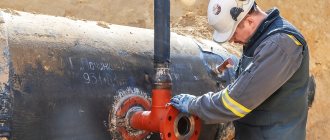
It should be understood that the requirements for the installation of pipelines of this type are quite high: welding and connecting high-pressure pipes is quite difficult. This task cannot always be accomplished at home. At the same time, installation of a pipeline of this type can only be carried out using special, expensive steel with an anti-corrosion coating.
Requirements for high pressure pipelines
The design and installation of high-pressure pipelines is a technologically complex process that is subject to strict requirements. They are set out in numerous state standards, and implementation is controlled by supervisory authorities at the federal and municipal levels. Coordination and approval of the project of an individual pipeline largely depends on the selected materials: pipes, connecting elements, shut-off valves, consumables and, of course, sealants. Taking into account the consequences of an interruption in the operation of a high-pressure pipeline or an emergency situation in at least one of its sections, the issue of the quality and effectiveness of sealing materials is resolved individually each time. Taking into account the transported substance, its aggressiveness, pressure, temperature and possible exposure to external factors.
High pressure pipelines
The main function of the pipeline is to deliver the product to the place of consumption or processing. The highway transports gaseous, vaporous, and liquid substances over a variety of distances. This can be hundreds of kilometers, if we talk about large federal highways, or local networks, the so-called technological pipelines. During operation, the pipeline and each individual section are constantly subject to loads. They are divided into basic and additional. The main load on the pipeline comes from the pressure of the transported product. Design, selection of materials, installation and launch of the pipeline are always carried out taking into account the design, conditional, operating and test pressure. Engineers calculate the minimum and possible maximum load on the pipeline in normal and emergency situations.
Calculations are performed by computer technology, and based on these results, acceptable elements of the entire pipeline are purchased, with mandatory consideration of pressure pulsation, temperature changes (internal and external), vibrations, water hammer, changes in the environment, etc.
A high-pressure pipeline is a network with a pressure of the transported substance exceeding 25 atmospheres. In this case, the type of substance and its aggressiveness are of fundamental importance. On the territory of Russia there are many main lines with a pressure of over 100 atmospheres, which are objects of increased danger and require special conditions during installation and further use. In general, the installation of a high-pressure pipeline is carried out strictly according to designs and technical specifications developed separately for the chemical, gas, oil and oil refining industries, water and steam supply systems.
High pressure piping materials and connections
The main pipeline is a system consisting of: • Pipes themselves • Fastening and connecting elements • Seals • Shut-off and control valves • Support structures • Instrumentation • Anti-corrosion elements • And other parts that are used in accordance with the project.
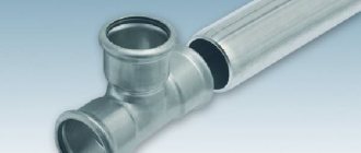
The following types of pipes are intended for high-pressure lines: • Steel - cold-rolled carbon and alloy steel • Copper • Plastic - made of polyethylene
There are two types of connections between pipes, as well as with branches and various devices: • Detachable • One-piece
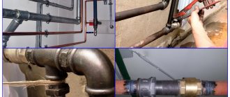
Let us immediately make a reservation that under conditions of high pressure of the transported substance, they strive to minimize detachable connections. A seamless pipeline is the most airtight and safe. Permanent connections are made using seam welding, fusion welding or soldering.
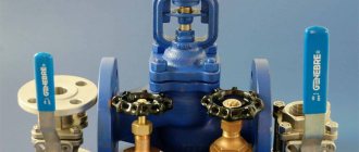
Detachable connections are also obtained in several ways. One of the most common is the flange connection. There are also threaded, fitting, yoke, groove.
The design of the flange connection resembles a sandwich. In a professional environment they call it “flange sandwich”. A gasket and an O-ring are placed between the two flanges, and the parts are fastened with bolts and nuts. To seal flange connections, gaskets are used: • Metallic • Non-metallic • Combined
Hydraulic fittings and flanges
If hydraulic system components cannot be removed, their connections can be soldered or welded to ensure maximum reliability. However, if components need to be serviced or replaced, such connections will inevitably be damaged, so all but highly specialized hydraulic systems require detachable connections. As a result, fitting designs have undergone significant improvements over the years to improve performance and ease of installation, but the overall function of these components remains relatively unchanged.
The connections seal the working fluid in the hydraulic system in one of two ways:
- metal-to-metal seal with hermetically sealed contact between two metal surfaces;
- using O-rings that hold fluid under pressure within the system by compressing the elastomeric seal.
In both cases, when the connection between the mating parts of the fitting (or the fitting and the hydraulic component port) is tightened, the mating surfaces are brought together to form a high-pressure seal.
Connections with metal-to-metal seal
The threads on pipe fittings are tapered, and the tightness of the connection depends on the tension created when the threads of the mating male thread come into contact with the threads of the mating female thread (Figure 1). Pipe threads are susceptible to leaks because they are torque-sensitive—over-tightening causes the threads to deform, creating leak paths. In addition, pipe threads are susceptible to weakening due to vibration and significant temperature changes, which are not uncommon in hydraulic systems.
Figure 1. Pipe thread fittings have given way to new designs that simplify assembly and maintenance and reduce or eliminate leaks. The illustration shows a 90° elbow fitting with pipe threads on one end permanently screwed into a port. At the other end of the fitting there is a cylindrical thread with a cone for a flared pipe.
Thread leaks should always be expected when using tube fittings in high pressure hydraulic systems. Because pipe threads are tapered, repeated assembly and disassembly only exacerbates the problem of leakage due to distorted threads, especially if the stamped fitting connects to the port of a cast iron component of the system. Sealants are recommended for joining pipe fittings and are a potential source of contamination, which is another reason why most designers consider them obsolete for use in hydraulic systems.
Developed many years ago to improve piping connections (Figure 2), flare fittings are probably still the design most commonly used in hydraulic systems. When the union nut is tightened, the fitting is pressed against the flared part of the pipe, as a result of which a reliable seal is formed between the surfaces of the flared part of the pipe and the conical part of the fitting. 37° cone angle fittings are designed for use with thin to medium wall thickness pipes in hydraulic systems with operating pressures up to 200 bar. Since flaring of thick-walled pipes is technologically difficult, it is not recommended to use conical fittings to connect them. 37° cone fittings are suitable for hydraulic systems operating at temperatures from -50 to +200° C. They are more compact than most other fittings and can easily be adapted to metric pipe sizes. Such fittings are widely available and are among the most budget-friendly.
Figure 2. Cone fittings include a number of design improvements and provide improved performance compared to tube fittings. They are used to connect pipes with small and medium wall thickness.
Connections without pipe flaring (Fig. 3) are gradually gaining acceptance as they require minimal pipe preparation. They are suitable for an average operating pressure of 200 bar and are more resistant to vibration than other types of metal-to-metal seal connections. When the union nut is tightened, the sealing sleeve fits inside the fitting. In this case, the sealing sleeve is compressed around the pipe, which leads first to its contact with the outer surface of the pipe, and then to recess into the surface, creating a forced seal. In this regard, connections without pipe flaring should be used for pipes with medium and large wall thickness.
Figure 3. Non-flared pipe fittings have advantages similar to those of cone fittings and are used to connect pipes with medium to large wall thicknesses.
O-ring connections
Surprisingly, the problem of hydraulic leaks may have been eliminated more than a couple of generations ago. Although leak-free hydraulic operation was always desirable, the need for it became more critical as operating pressures increased, most notably in military aircraft hydraulic systems during World War II. Previously, typical operating pressures ranged from 55 to 70 bar. The post-war era was marked by the development of systems designed to operate at pressures up to 100 bar and above, under conditions of high duty cycles and water hammer. Soon the usual operating pressure increased to 170...200 bar, which is by no means uncommon today.
O-ring seal connections continue to gain acceptance among hydraulic system designers around the world. There are currently three main types of these connections: SAE straight thread O-ring fittings, end seal fittings, and O-ring flange connections. The choice between straight thread O-ring fittings and end seal fittings typically depends on factors such as installation location, wrench space available, or individual preference. Flanged connections are typically used on pipes larger than 7/8” (22 mm) in outside diameter or in high pressure hydraulic systems.
When using a fitting with a parallel thread and an O-ring, the latter is placed between the threads and the wrench face along the outer diameter of the male threaded fitting (Fig. 4). This forms a hermetic seal between the fitting and the seating surface of the mating part with internal threads. Straight thread O-ring fittings are divided into two main groups: adjustable and non-adjustable. Non-adjustable (without the ability to select a position) include plugs and nipples. They simply screw into the port with no alignment required. Adjustable fittings, such as elbows and tees, must be oriented in a specific direction when installed.
Figure 4. Non-adjustable fittings (left) and adjustable SAE straight thread O-ring fittings are easy to assemble and provide a high leak-tight seal.
The main design difference between these two types of connections is that plugs and nipples do not have a lock nut and do not require a back-up washer to seal effectively. The tightness of the connection here depends on the force of pressing the sealing ring against the port chamfer. Adjustable fittings are screwed into the mating part, rotated in the desired direction and secured by tightening the lock nut. As the lock nut is tightened, the stationary back-up washer presses against the O-ring to form a tight seal. The assembly of these connections is always predictable because after installing the fittings, the technician only needs to ensure that the backing washer is in tight contact with the port seating surface and is properly secured.
In end seal connections, the seal is made between the flat ground surface of the female mating part and the O-ring located in a groove machined into the end of the male mating part (Figure 5). When the union nut is tightened, the O-ring is compressed between the ends of the mating parts.
Figure 5. An end seal fitting uses an O-ring that fits into an annular groove in a male mating part that mates with the flat, smooth surface of the female mating part.
Connections with O-rings have a number of advantages over connections with a metal-to-metal seal. Although under- or over-torque can cause leaks in any fitting, metal-to-metal fittings are more likely to leak because they require a higher torque over a smaller tolerance range. This increases the risk of thread stripping, cracking and deformation of connection parts, which increases the likelihood of seal failure. With rubber-to-metal sealing, O-ring joints do not deform metal parts, providing a tactile sensation of achieving a tight seal when tightening. Metal-to-metal fittings are tightened gradually, so the technician may have trouble recognizing when the connection is tight enough but not yet overtightened.
On the other hand, O-ring fittings are more expensive than similarly sized metal-to-metal fittings, and care must be taken during installation to ensure the O-ring does not fall out and become damaged when tightened. Additionally, O-rings are not interchangeable for all connections. Incorrect O-ring selection or reusing a deformed O-ring to replace a damaged one may result in leakage. Once removed, the O-ring cannot be reused, even if it is not visibly damaged or deformed.
Several manufacturers offer specially designed high-pressure fittings that are leak-tight, including drip-tight, similar to end-seal fittings, and interchangeable with many types of fittings used around the world. Testing has shown that these fittings exceed all applicable requirements without any evidence of leakage when subjected to vibration rates up to 15 times higher than those typically observed in positive displacement hydraulic actuators. The design of such fittings may seem unified, but they should not be combined with fittings from different manufacturers.
Hydraulic flanges
Tightening fittings on pipes larger than 1” (25.4 mm) outside diameter requires large hex nuts, which in turn require the use of large wrenches to apply sufficient torque. To assemble such connections, a fairly large space is required due to the need to work with large wrenches. In addition, the strength and fatigue level of the technician may adversely affect the correct assembly. In some cases, to apply the required torque, wrench extensions (extensions) may be needed.
Standard hydraulic flanges (Figure 6) solve both of the above problems. Flanges use an O-ring to seal the connection and hold fluid under pressure. The elastomeric O-ring is located in a groove in the flange and mates with the flat bearing surface of the port. This design is similar to a fitting with an end seal. The O-ring flange is bolted to the port, eliminating the need for a large wrench when assembling a large diameter line. To avoid creating a gap that could force the O-ring under high pressure, it is important to apply uniform torque to all bolts when tightening flange connections.
Figure 6. Flanges are available in a variety of standard designs to suit most hydraulic applications.
Manufacturers also offer split flanges suitable for installation into existing systems. A split flange connection consists of three main elements: a flange adapter that is permanently connected (usually brazed or welded) to the pipe, an O-ring that fits into a groove in the end of the flange, and a two-piece clamp with bolts to connect the split flange. flange with mating part.
All mating surfaces of flange connections must be clean and smooth. If any of them are scratched, rough or uneven, the connections are more likely to leak. In addition, O-rings that come into contact with rough surfaces wear out much faster. To assemble structures in which the mutual perpendicularity of parts is important, all parts must be manufactured with appropriate tolerances. Despite the fact that the roughness of the working surface of the flange Ra 1.6 is acceptable, most flange manufacturers prefer and recommend manufacturing flanges with a roughness Ra 0.8 in order to better ensure the tightness of connections.
In a properly designed split flange, the collar protrudes approximately 0.25...0.76 mm beyond the surface of the clamp, which ensures sufficient pressure of the sealing ring to the supporting surface (Fig. 7). However, the clamp halves do not actually contact the supporting surface. The most important procedure when installing a split flange connection is to gradually (evenly and cross-tighten) all mounting bolts. Pneumatic impact wrenches are not recommended for this job as they are difficult to control and may overtighten.
Figure 7. In a properly designed and assembled connection with a split flange, there is a uniform gap between the supporting surface of the port and the clamp halves, equal to 0.25 ... 0.76 mm.
Fully tightening one of the bolts while the other bolts are not tightened can lead to an upward skew of the flange (Fig. 8). In this case, the sealing ring is squeezed out, which reduces the tightness of the connection. If the bolts are overtightened, the flange will sometimes skew “downwards” until it touches the supporting surface of the port, causing the bolts to bend outward. Either way, the result will most likely be a leaky connection.
Figure 8. Uneven tightening of split flange bolts can cause the flange to skew upward and damage the O-ring (left), while excessive torque (right) can cause the flange to warp and bend the bolts.
Controlling the movement of machinery using hydraulic power requires competence and experience in various fields. Load calculation, checking the kinematic diagram, motion trajectory, selection of materials and equipment. Specialists of PKTs Kinematika LLC will help you make the right choice, provide justifications, documentation, technical descriptions and certificates for hydraulic components, make mathematical calculations and offer optimization options.
Which highways are used to supply various consumers?
The above SNiP clearly defines the scope of application of gas pipelines of a certain category. It is clear that supplying gas through high-pressure lines to household consumers is impractical, since it will be necessary to install pressure-reducing equipment in front of each device. In addition, a low-pressure gas pipeline allows for greater safety at the household level.
So, the scope of application of gas lines of various pressures is as follows:
High pressure gas line of the first category
- The high-pressure line of the first category is used only to supply industrial consumers whose operating technology requires significant fuel consumption and pressure (steel-smelting furnaces and other similar equipment). In addition, such lines are used to supply fuel to boiler houses of such enterprises, provided that they are equipped with the appropriate equipment. In this case, the connection to the gas supply system is carried out in accordance with a specially developed project.
- Gas can be supplied to the rest of the production premises via high-pressure lines of category 2. The same main line is used to supply various types of boiler houses (attached, roof, built-in) installed for heating industrial buildings.
- Medium gas pressure in the mains is used to supply domestic and administrative premises, boiler rooms for their heating. In addition, the same pipelines are being laid to supply public buildings, the supply of which requires an increased volume of gaseous fuel.
- All household consumers are connected only to low pressure lines, which can ensure maximum operational safety. The use of high and medium pressure lines to supply residential buildings is not permitted.
PIPE THREADED CONNECTIONS WITH 90° FLARE ORFS
90° Flare Pipe Connections The company's fitting, manufactured according to ISO 8434-3/SAE J1453, is a mechanical connection traditionally used in high pressure hydraulic systems.
Sealing occurs by mating metal surfaces and using an O-ring pressed into the end of the fitting.
A reliable connection between the fitting body and the flared pipe is achieved through a sealing nut and a locking ring, and ensures quick assembly and disassembly of the connection.
- Screw-in fittings
- Extended screw-in fittings
- Adjustable screw fittings
- Screw-in fittings, adjustable, extended
- Screw-in fittings with union nut
- Bulkhead connections
- Feedthrough connections
- Feedthrough connections with union nut
- Adapters
- Welded connections
- Connections for connecting measuring devices
- Stubs
- Accessories and spare parts
Maximum permissible pressure
The pressure during gas testing is increased gradually with constant inspection of the pipes: 30% of the maximum pressure, 60% of the maximum pressure and the peak value.
During examinations, the increase in pressure stops.
Defects in transverse seams found during testing are not corrected.
The section of pipe with damage is cut out and replaced with a new segment.
The length of the sections between the seams should be at least 20 centimeters with a pipe diameter (which is recommended for water supply in an apartment as described in this article) over 150 millimeters.
With a smaller diameter, the straight section should be at least 10 centimeters.
When maintaining high pressure for a long time , the pipes are constantly inspected.
If the pressure has increased due to heating, then the test pressure is reduced smoothly (read about the causes of water hammer in the pipeline here) to the required level.
Connection with inch and metric threads and 60° seal according to DIN 3863
The type of compounds originating from England is also common in the markets of Europe, Russia, North and South America, Asia, and Japan. This type of connection has a number of characteristic features:
- inch thread;
- cone angle 60 degrees. A connection with an external thread has an internal cone; a connection with a female thread has an external cone of 60°.
Pipe connections of this type are divided into groups:
- screw-in fittings;
- screw-in adjustable fittings;
- screw-in fittings, adjustable, extended;
- screw-in fittings with internal thread;
- feed-through connections with external thread;
- fitting-nut connections;
- feed-through connections with internal thread;
- stubs.
Our achievements work for you
- stability, durability and reliability
- unique performance
- ease of maintenance and service
- diverse application possibilities
- compact design, the equipment takes up virtually no space on the vehicle for washing
- left and right rotation possible
- Wear-resistant URACA mushroom valves
- resistance to recirculated water
- ability to select different pressure and power levels
PIPE CONNECTIONS, CONE ANGLE 60 DEGREES. BSP
Connections, cone angle 60 degrees. The Cast fitting, manufactured to BSI 5200, is an adapter traditionally used in high pressure hydraulic systems.
Sealing occurs through the mating of metal surfaces, eliminating deformation, as well as using an O-ring pressed onto the outer part of the fitting with a cone angle of 60°.
A reliable connection between the fitting body and the flared pipe is achieved using a union nut and ensures quick assembly and disassembly of the connection
- Screw-in fittings
- Adjustable screw fittings
- Screw-in fittings, adjustable, extended
- Screw-in fittings with internal thread
- Feed-through fitting-to-fitting adapters
- Adapters through fitting-nut
- Nut-to-nut adapters
- Stubs
Manufacturing technology
Turned tees according to GOST 22822 are manufactured using the following technology:
- cutting - giving the workpiece a T-shaped configuration;
- groove - giving a cylindrical shape to the outer surfaces of the pipes;
- drilling – a through hole with a blind hole adjacent to its middle;
- cutting edges - chamfers for welding in accordance with GOST regulations.
Compared to a stamped fitting of the same size, the production of a GOST 22822 tee costs three times more. On the other hand, stamped fittings are not designed to withstand high pressure.
Advantages of pipe connections
Connecting pipes using adapters has a number of advantages, namely:
- ease of installation and subsequent repair of the pipeline;
- reliability and tightness with easy installation;
- possibility of modernization;
- the possibility of pre-assembly and installation in hard-to-reach places, as well as in fire and explosion hazardous areas;
- the range of pipe connections allows you to assemble a hydraulic circuit of any complexity;
- presentable appearance of pipeline systems;
- there is no need to employ welders of 5-6 categories;
- there is no need to use X-ray control after installation.
Pipe connections according to DIN 3859-1 are made from drawn or forged steel, according to DIN 3859 - from brass, acid-resistant or heat-resistant steel, maintaining structural strength for decades. Protection of fittings from environmental influences is carried out by electrozinc plating and chrome plating of the outer surface.
Buy polyethylene pipes in Kazan wholesale from the manufacturer
offers high-quality polyethylene pipes, which can be purchased in bulk by placing an order by phone or online. On our website you can learn more about the technical characteristics of such a popular item as a polyethylene pipe. The price will please you with its affordable price, and the quality will leave no doubt that we are the leading supplier of pipes in the region.
offers to buy polyethylene pipes from the manufacturer. You can buy polyethylene pipes wholesale from us. We will deliver our products promptly and completely safe.
The products of TPK KAZAN PIPE PLANT meet international quality standards and have GOST certificates. By contacting us, you can count on an individual approach.
Brands and indicators of polyethylene pipes
If we consider the technical capabilities of polyethylene pipes, we should start from their purpose: heating, water supply, or pipes intended for the sewage system perform slightly different functions. First, pay attention to the manufacturer's brand and country of origin of the product. Next, familiarize yourself with the raw materials from which the product is made, check the data on resistance to high pressure and the diameter of the product. If you decide to install polyethylene pipes, it is also important to understand what polyethylene is and what standards are used in production.
Buy pipe connections
We offer a wide range of pipe connections of different types and sizes. Today, all pipe connections are divided into four main groups::
- Connections with metric thread and 24° sealing cone according to DIN 2353/ISO 8434-1 (connection made using cutting ring and nut)
- Connections with inch threads and 37° (74°) sealing cone per SAE J514 (connection made by flaring pipe, sleeve and nut)
- Connections with inch thread and 90° seal according to SAE J1453 (connection is made by flaring a pipe, sleeve, nut)
- Connections with inch and metric threads and 60° seal according to DIN 3863 (connection is made using adapters).
In our company you can buy pipe connections made of both carbon and stainless steel . Today, our warehouse offers the widest range of pipe connections and adapters in Russia. We are constantly working to replenish our inventory, guaranteeing you the minimum delivery time for goods.
Pipe connections are a popular method of installing rigid hydraulic pipes; they are produced by such large and well-known global companies as Rastelli Raccordi, Trelleborg, VOSS, Larga, ARCO, Hydroscand . However, the best price-quality ratio is offered by the Italian manufacturer CAST.
Our company recommends the products of Cast SpA, a leader in the production of fittings, adapters, tees, nuts, cutting rings, pipe connections and fittings for high-pressure hoses.
Purpose of fittings for high pressure hoses
To connect to the hydraulic hose system, connecting parts - fittings - are used. They allow you to quickly and effortlessly assemble a system of any configuration.
The simplest structure of the part: a nut for fixing and a fitting for connection. Depending on the system in which the connecting element is used, it has a different shape, thread and size.
Parts requirements
Devices for connecting RVD must comply with certain standards.
The technical characteristics of fittings are regulated by GOST.
They must be manufactured taking into account the load values in the system in strict accordance with the requirements (maximum pressure - up to 20 atm), maximum temperature indicators of fittings (100 - 220 ° C), and also be inert to aggressive chemical compounds.
Types of fittings for high pressure hoses
Depending on the application, fittings (both for high pressure hoses and other systems) are:
- Bends, corners - are used when it is necessary to change the direction of laid pipes by 45, 90 or 120°.
- Tees and manifolds - help make branches from the main line in one direction.
- Crosses - serve for branching in different directions.
- Couplings – ensure the joining of pipes of the same diameter on a straight section of line.
- Adapters - bends, nipples, "American" - connect pipes of various types.
- Plugs, plugs, caps - used for tightly sealing the ends of pipelines.
- Fittings - if necessary, connect a pipe with a flexible hose - an irreplaceable part.
For metal pipes, fittings are made from both ferrous metals (cast iron, steel) and non-ferrous metals (brass, copper). When installing plastic systems, polypropylene connectors are used. Regardless of the material, the parts must withstand the necessary loads.
More about RVD
High pressure hoses (HHP) are flexible pipeline systems designed for supplying liquid media. Most often they are used in various mechanisms and systems of machines and equipment.
Types of fittings for high pressure hoses
They are made from two or more rubber, gas-oil-resistant hoses of different diameters, inserted into one another according to the nesting doll principle.
To give additional strength, they are reinforced with high-strength braids or windings. Depending on the braid, the hoses can withstand fairly high operating pressure.
The main characteristics include the operating temperature of the pipeline and the bending radius of the hose. Pipelines can withstand temperatures from -40 to +100°.
For extreme operating conditions, special high pressure hoses are produced with a temperature range from -50 to +155. The bend radius of the sleeve determines how convenient it is to work with it. The higher this indicator, the less comfortable it is to install and operate.
For the installation of a hydraulic system, steel tips coated with a galvanic protective layer are mainly used. Fittings made of stainless steel or non-ferrous metals are less common.
About types of hoses
Currently used high-pressure hoses (or hoses) are divided into 5 categories:
HP hose with installed fitting with union nut
- Pressure (maximum pressure – 10 atmospheres, temperature – +175°). They are used for transporting steam, compressed air, fuel mixtures, acids (with a concentration of less than 20%).
- Pressure and suction (maximum pressure – 10 atmospheres, temperature – +90°). They are used in pumping systems for chemical compounds, as well as food products and drinking water.
- Fuel dispensers (maximum pressure – 5 atmospheres, temperature – +120°). Used for transporting liquid fuel. Externally and internally they have a protective coating against static.
- Pneumatic (maximum pressure – 5 atmospheres, temperature – +100°). Used to transmit air in pneumatic systems.
- Gas welding (maximum pressure – 20 atmospheres, temperature – +70°). They are used to transfer the medium (flammable gas) from the cylinder to the cutter.
Requirements for fittings for high pressure hoses
Fasteners used to connect high-pressure hoses must meet certain requirements (which are separately prescribed in GOSTs):
- Withstand pressure – up to 10-20 atmospheres (depending on the application system described above).
- Temperature limit – up to +100-220°.
- Resistance to aggressive chemical compounds.