Plumbing, it would seem, does not provide much reason to delve into the jungle of technologies, mechanisms, or engage in scrupulous calculations to build complex schemes. But such a vision is a superficial look at plumbing. The real plumbing industry is in no way inferior in complexity to the processes and, like many other industries, requires a professional approach. In turn, professionalism is a solid store of knowledge on which plumbing is based. Let’s dive (albeit not too deeply) into the plumbing training stream in order to get one step closer to the professional status of a plumber.
Hydraulic calculation of a complex gas pipeline
MINISTRY OF EDUCATION AND SCIENCE OF THE RUSSIAN FEDERATION
FSBEI HPE "VORONEZH STATE TECHNICAL UNIVERSITY"
Aviation Faculty
Department of NGOT
Specialty 130501 “Design, construction and operation of gas and oil pipelines and gas and oil storage facilities”
COURSE WORK
in the discipline "Fundamentals of the theory and design of energy systems of gas and oil pipelines and gas and oil storage facilities"
Topic: “Hydraulic calculation of a complex gas pipeline”
Completed by student gr. NGD-091 A.S. Sokolov
Head A.I. Zhitenev
Voronezh 2013
EXERCISE
for course work in the discipline “Fundamentals of the theory and design of energy systems of gas and oil pipelines and gas and oil storage facilities”
Project topic: “Hydraulic calculation of a complex gas pipeline”
Student of group NGD-091 Sokolov Alexey Sergeevich
Task No. 1
. In accordance with the assignment option (Appendix A), draw up an analytical dependence for an equivalent gas pipeline, present the conclusion of this dependence with intermediate results and detailed comments.
. Calculate the capacity of a complex gas pipeline.
. Calculate the pressure at all intermediate points and plot the dependence of the pressure on the longitudinal coordinate of the gas pipeline for each thread.
Task No. 2
1. In accordance with the task option, calculate the diameters of the pipeline system to ensure standard pressure loss values.
. Determine the initial pressure required to supply gas to all consumers in accordance with the initial data (Appendix B).
. Calculate the pressure at all intermediate points and plot the dependence of the pressure on the longitudinal coordinate of the gas pipeline for each thread.
Head A.I. Zhitenev
The task was accepted by student A.S. Sokolov
Introduction
. Hydraulic calculation of a complex high-pressure gas pipeline
.1 Determining the capacity of a complex gas pipeline
.2 Estimation of the resulting flow in the system
.3 Construction of the dependence of pressure in an equivalent gas pipeline on the longitudinal coordinate
.4 Pressure distribution across sections of the pipeline system
. Hydraulic calculation of a complex low-pressure gas pipeline
.1 Determination of pressure at network nodes
.2 Determination of the diameter of distribution network sections
.3 Bringing the diameters of network sections to standard values
.4 Determination of the dependence of pressure in the network on the longitudinal coordinate
Conclusion
Bibliography
Applications
Calculation of flow in a limited area
If the gas pipeline consists of separate sections, then the calculation of the total flow rate for each of them will have to be performed separately. But this is not difficult, since the calculations will require already known numbers.
Defining data using the program
Knowing the initial indicators, having access to the simultaneity table and technical data sheets of stoves and boilers, you can begin the calculation.
To do this, perform the following steps (the example is given for a low-pressure intra-house gas pipeline):
- The number of boilers is multiplied by the productivity of each of them.
- The resulting value is multiplied by the simultaneity coefficient specified using a special table for this type of consumer.
- The number of stoves intended for cooking is multiplied by the productivity of each of them.
- The value obtained after the previous operation is multiplied by the simultaneity coefficient taken from a special table.
- The resulting amounts for boilers and stoves are summed up.
Similar manipulations are carried out for all sections of the gas pipeline. The obtained data is entered into the appropriate columns of the program with which the calculations are performed. The electronics does everything else itself.
Calculation using formulas
This type of hydraulic calculation is similar to that described above, that is, the same data will be required, but the procedure will be lengthy. Since everything will have to be done manually, in addition, the designer will need to carry out a number of intermediate operations in order to use the obtained values for the final calculation.
You will also have to devote quite a lot of time to understand many concepts and issues that a person does not encounter when using a special program. The validity of the above can be verified by familiarizing yourself with the formulas to be used.
Calculation using formulas is complex and therefore not accessible to everyone. The picture shows formulas for calculating the pressure drop in the high, medium and low pressure network and the coefficient of hydraulic friction
In the application of formulas, as in the case of hydraulic calculations using a special program, there are features for low, medium and, of course, high pressure gas pipelines. And it’s worth remembering, since a mistake is always fraught with significant financial costs.
Calculations using nomograms
Any special nomogram is a table that shows a number of values, by studying which you can obtain the desired indicators without performing calculations. In the case of hydraulic calculations, the diameter of the pipe and the thickness of its walls.
Nomograms for calculation are a simple way to obtain the necessary information. It is enough to refer to the lines that meet the specified network characteristics
There are separate nomograms for polyethylene and steel products. When calculating them, standard data were used, for example, the roughness of the internal walls. Therefore, you don’t have to worry about the correctness of the information.
Gravity
Gravity is one of the four forces of nature. The strength of the gravitational force between two objects depends on the mass of those objects. The more massive the objects, the stronger the gravitational pull.
When water is poured out of a container, the Earth's gravity pulls the water toward the Earth's surface. You can observe the same effect if you place two buckets of water at different heights and connect them with a tube.
It is enough to set the flow of liquid in the tube from one bucket to another, after which the force of gravity will work, and the overflow process will continue spontaneously. Gravity, applied forces and atmospheric pressure are static factors that apply equally to fluids at rest or in motion.
The forces of inertia and friction are dynamic factors that act only on fluids in motion. The mathematical sum of gravity, applied force and atmospheric pressure represents the static pressure obtained in any zone of the fluid at any time.
Determination of the capacity of GDS pipelines
B.K. Kovalev, Deputy Director for R&D
Recently, we have increasingly come across examples where orders for industrial gas equipment are placed by managers who do not have sufficient experience and technical knowledge regarding the subject of procurement. Sometimes the result is an incompletely correct application or a fundamentally incorrect selection of the ordered equipment. One of the most common mistakes is the selection of nominal cross-sections of the inlet and outlet pipelines of a gas distribution station, focused only on the nominal values of gas pressure in the pipeline without taking into account the gas flow rate. The purpose of this article is to provide recommendations for determining the capacity of gas distribution station pipelines, allowing, when choosing the standard size of a gas distribution station, to carry out a preliminary assessment of its performance for specific values of operating pressures and nominal diameters of inlet and outlet pipelines.
When choosing the required standard sizes of GDS equipment, one of the main criteria is productivity, which largely depends on the throughput of the inlet and outlet pipelines.
The throughput of the gas distribution station pipelines is calculated taking into account the requirements of regulatory documents that limit the maximum permissible gas flow rate in the pipeline to 25 m/s. In turn, the gas flow rate depends mainly on the gas pressure and the cross-sectional area of the pipeline, as well as on the compressibility of the gas and its temperature.
The throughput capacity of a pipeline can be calculated from the classical formula for the speed of gas movement in a gas pipeline (Handbook for the design of main gas pipelines, edited by A.K. Dertsakyan, 1977):
where W is the speed of gas movement in the gas pipeline, m/sec; Q is the gas flow through a given section (at 20°C and 760 mm Hg), m 3 /h; z is the compressibility coefficient (for an ideal gas z = 1); T = (273 + t °C) — gas temperature, °K; D is the internal diameter of the pipeline, cm; p = (Pwork + 1.033) - absolute gas pressure, kgf/cm 2 (atm); In the SI system (1 kgf/cm 2 = 0.098 MPa; 1 mm = 0.1 cm), the specified formula will take the following form:
where D is the internal diameter of the pipeline, mm; p = (Pwork + 0.1012) - absolute gas pressure, MPa. It follows that the pipeline capacity Qmax, corresponding to the maximum gas flow rate w = 25 m/sec, is determined by the formula:
For preliminary calculations, we can take z = 1; T = 20? C = 293? K and carry out calculations with a sufficient degree of reliability using the simplified formula:
The throughput values of pipelines with the most common nominal diameters in gas distribution systems at various gas pressures are given in Table 1.
Source
Static pressure
Static pressure exists in addition to any dynamic factors that may also be present simultaneously. Pascal's law states:
The pressure created by the liquid acts equally in all directions and at right angles to the contained surfaces.
This definition applies only to liquids that are at complete rest or practically motionless. The definition is also valid only for factors that make up the static hydraulic pressure.
Obviously, when speed becomes a factor, direction comes into play. A force tied to speed must also have a direction. Therefore, Pascal's law, as such, does not apply to the dynamic power factors of fluid flow.
The speed of flow depends on many factors, including the layer-by-layer separation of the liquid mass, as well as resistance created by various factors. The dynamic factors of inertia and friction are tied to static factors. The velocity head and pressure loss are tied to the hydrostatic head of the liquid. However, part of the velocity head can always be converted into static pressure.
Force, which can be caused by pressure or pressure when handling liquids, is necessary to start the movement of a body when it is at rest, and is present in some form when the movement of the body is blocked.
Therefore, whenever the speed of movement of a fluid is set, part of its initial static pressure is used to organize this speed, which subsequently exists as a pressure speed.
Rules for performing calculations
It was stated above that the procedure for any hydraulic calculation is regulated by the profile Code of Rules with the number 42-101–2003.
The document indicates that the main way to perform the calculation is to use a computer for this purpose with special programs that allow you to calculate the planned pressure loss between sections of the future gas pipeline or the required pipe diameter.
Any hydraulic calculation is performed after creating a calculation diagram that includes the main indicators. Moreover, the user enters known data into the appropriate columns
If there are no such programs or a person believes that their use is inappropriate, then other methods permitted by the Code of Rules can be used.
Which include:
- calculation using the formulas given in the SP is the most complex method of calculation;
- calculation using so-called nomograms is a simpler option than using formulas, because you don’t have to make any calculations, because the necessary data is indicated in a special table and given in the Code of Rules, and you just need to select them.
Any of the calculation methods leads to the same results. Therefore, the newly built gas pipeline will be able to ensure timely, uninterrupted supply of the planned amount of fuel even during the hours of its maximum use.
Influence of pipe material on calculation
For the construction of gas pipelines, you can use pipes made only from certain materials: steel, polyethylene. In some cases, copper products are used. Metal-plastic structures will soon be widely used.
Each pipe has a roughness, which leads to linear resistance, which affects the process of gas movement. Moreover, this figure is significantly higher for steel products than for plastic ones.
Today, the necessary information can only be obtained for steel and polyethylene pipes. As a result, design and hydraulic calculations can only be carried out taking into account their characteristics, which is required by the relevant Code of Practice. The document also contains the data necessary for the calculation.
The roughness coefficient is always equal to the following values:
- for all polyethylene pipes, regardless of whether they are new or not, - 0.007 cm;
- for already used steel products - 0.1 cm;
- for new steel structures - 0.01 cm.
For any other types of pipes this indicator is not indicated in the Code of Practice. Therefore, they should not be used for the construction of a new gas pipeline, since Gorgaz specialists may require adjustments to be made. And these are again additional costs.
Hydraulic calculation of a gas pipeline: methods and methods of calculation + calculation example
For safe and trouble-free operation of the gas supply, it must be designed and calculated
It is important to perfectly select pipes for mains of all types of pressure, ensuring a stable supply of gas to devices
To ensure that the selection of pipes, fittings and equipment is as accurate as possible, a hydraulic calculation of the pipeline is performed. How to make it? Admit it, you are not too knowledgeable about this issue, let's figure it out.
We offer you to familiarize yourself with carefully selected and thoroughly processed information about options for producing hydraulic calculations for gas pipeline systems. Using the data we present will ensure that the devices are supplied with blue fuel with the required pressure parameters. Carefully verified data is based on the regulations of regulatory documentation.
The article describes in great detail the principles and schemes for performing calculations. An example of performing calculations is given. Graphic applications and video instructions are used as a useful informative addition.
General provisions
When designing pipelines for gas transport, the choice of pipe sizes is carried out on the basis of their hydraulic calculation, which aims to determine the internal diameter of the pipes to pass the required amount of gas, and, what is important to note, with pressure losses acceptable for specific conditions. The main feature of gas distribution networks in a populated area, which distinguishes them from other engineering systems and, accordingly, determines the specifics of hydraulic calculations, is the absence of pressure blowers along the route. Transportation is carried out only at the expense of energy received from compressor units on the main networks
In this regard, pressure losses in gas supply systems within a populated area are quite strictly regulated (see paragraph 3.25). Thus, by properly performing hydraulic calculations, the designer must obtain an optimal solution: on the one hand, the pipe diameters should not create extremely large pressure losses during movement, and on the other hand, one should naturally strive for low material consumption of the systems.
Another feature of gas distribution systems is the mandatory consideration of the compressibility of the transported medium. This somewhat complicates the main calculated dependencies, the conclusion of which is contained in. Thus, for a separate design section of a low-pressure gas network, pressure loss (Pa) due to friction is determined by the formula
.
The calculated section of the medium or high pressure network will already be characterized by a quadratic pressure drop (kPa2)
.
In the presented formulas, it is naturally important to specify the calculated relationship for the coefficient of hydraulic friction and the value of the absolute roughness of the inner surface.
Hydraulic calculation can be done in three ways. The first of them is based on the use of nomograms (see, for example,), from which, for a given diameter and flow rate, it is possible to very simply determine the pressure loss in the area under consideration. The disadvantage is the low accuracy of the results obtained. The second method, which allows you to obtain more accurate results, involves the use of calculation tables (see, for example,). They contain numerical values of specific pressure losses (Pa/m, kPa2/m) for discrete values
And
. In this regard, there is a need to use linear interpolation, which somewhat complicates the calculation procedure. In addition, for the two methods considered, it is necessary to multiply the values taken from calculation tables or nomograms by a density coefficient. The third method is based on direct calculation using the formulas presented above using a computer or programmable calculators, and the latter must be able to calculate power expressions with real exponents. This method is especially useful for large volumes of calculations, but requires the designer to have at least a simple program.
In addition to linear losses due to friction when gas moves in pipelines, local resistance is created in certain elements of systems where changes in speed and direction of flow are characteristic. For external systems, their accounting is done quite simply by increasing the length of the calculated section by 10%. For internal systems, a detailed account of individual local resistances is required in accordance with the formula
,
where is the estimated length of the gas pipeline section;
-its actual length;
- the sum of the local resistance coefficients located in the considered design area;
-equivalent length of a straight section of a gas pipeline, the path pressure loss in which is equal to the pressure loss in local resistance with the value
. The last characteristic in the general case is determined by the formula
,
and for various flow regimes, formulas for the equivalent length can be found in 3.28 or, without calculating it, determined from nomograms or calculation tables.
When determining pressure losses in low-pressure gas pipelines, losses caused by the difference in density of gas and air must also be taken into account, that is, hydrostatic head, Pa,
,
Where
- difference in absolute elevations of the initial and final sections of the gas pipeline, m;
- acceleration of gravity;
And
-density of gas and air under normal conditions.
Pascal's law
The fundamental basis of modern hydraulics was formed when Blaise Pascal discovered that the action of fluid pressure is constant in any direction. The action of liquid pressure is directed at right angles to the surface area.
If a measuring device (pressure gauge) is placed under a layer of liquid at a certain depth and its sensitive element is directed in different directions, the pressure readings will remain unchanged in any position of the pressure gauge.
That is, the fluid pressure does not depend in any way on the change in direction. But the fluid pressure at each level depends on the depth parameter. If the pressure meter is moved closer to the surface of the liquid, the reading will decrease.
Accordingly, when diving, the measured readings will increase. Moreover, under conditions of doubling the depth, the pressure parameter will also double.
Pascal's law clearly demonstrates the effect of water pressure in the most familiar conditions for modern life. Hence the logical conclusion: fluid pressure should be considered directly proportional to the depth parameter. As an example, consider a rectangular container measuring 10x10x10 cm, which is filled with water to a depth of 10 cm, which in terms of volumetric component will be equal to 10 cm3 of liquid.
This volume of water of 10 cm3 weighs 1 kg. Using the available information and the calculation equation, it is easy to calculate the pressure at the bottom of the container. For example: the weight of a column of water with a height of 10 cm and a cross-sectional area of 1 cm2 is 100 g (0.1 kg). Hence the pressure per 1 cm2 area:
P = F / S = 100 / 1 = 100 Pa (0.00099 atmospheres)
If the depth of the water column triples, the weight will already be 3 * 0.1 = 300 g (0.3 kg), and the pressure will triple accordingly. Thus, the pressure at any depth of a liquid is equal to the weight of the liquid column at that depth divided by the cross-sectional area of the column.
Water column pressure: 1 - wall of the liquid container; 2 — pressure of the liquid column on the bottom of the vessel; 3 — pressure on the base of the container; A, C - areas of pressure on the sidewalls; B - straight water column; H - height of the liquid column The volume of liquid creating pressure is called the hydraulic pressure of the liquid. The fluid pressure, due to hydraulic pressure, also remains dependent on the density of the fluid.
PC computing option
Performing calculus using a computer is the least labor-intensive - all that is required of a person is to insert the necessary data into the appropriate columns.
Therefore, hydraulic calculations are done in a few minutes, and this operation does not require a large amount of knowledge, which is necessary when using formulas.
To perform it correctly, it is necessary to take the following data from the technical specifications:
- gas density;
- coefficient of kinetic viscosity;
- gas temperature in your region.
The necessary technical conditions are obtained from the city gas department of the locality in which the gas pipeline will be built. Actually, the design of any pipeline begins with the receipt of this document, because it contains all the basic requirements for its design.
Next, the developer needs to find out the gas consumption for each device that is planned to be connected to the gas pipeline. For example, if fuel will be transported to a private house, then stoves for cooking, all kinds of heating boilers are most often used there, and their passports always contain the necessary numbers.
In addition, you will need to know the number of burners for each stove that will be connected to the pipe.
At the next stage of collecting the necessary data, information is selected about the pressure drop at the installation sites of any equipment - this could be a meter, a shut-off valve, a thermal shut-off valve, a filter, or other elements.
In this case, it is easy to find the necessary numbers - they are contained in a special table attached to the passport of each product
The designer should pay attention to the fact that the pressure drop at maximum gas consumption must be indicated
From the special table attached to the product data sheet, you can find out information about pressure loss when connecting devices to the network
At the next stage, it is recommended to find out what the blue fuel pressure will be at the insertion point. Such information may contain the technical conditions of your city gas, a previously drawn up diagram of the future gas pipeline.
If the network consists of several sections, then they must be numbered and the actual length indicated. In addition, for each one, all variable indicators should be written down separately - this is the total flow rate of any device that will be used, pressure drop, and other values.
A simultaneity coefficient will be required. It takes into account the possibility of joint work of all gas consumers connected to the network. For example, all heating equipment located in an apartment building or private house.
Such data is used by a hydraulic calculation program to determine the maximum load on any section or entire gas pipeline.
For each individual apartment or house, the specified coefficient does not need to be calculated, since its values are known and indicated in the table below:
A table with simultaneity coefficients, data from which is used for any type of calculation. It is enough to select the column corresponding to a specific household appliance and take the desired number
If at some facility it is planned to use more than two heating boilers, furnaces, and storage tank water heaters, then the simultaneity indicator will always be 0.85. This is what you will need to indicate in the corresponding column used for the calculation of the program.
Next, you should indicate the diameter of the pipes, and you will also need their roughness coefficients, which will be used in the construction of the pipeline. These values are standard and can be easily found in the Rulebook.
About working with microflows
If the task does not involve working with flows at a speed of more than 1.5 m/s and we are talking about a gaseous medium, then you can use sensors of the MFS02 series (Micro Flow Sense).
MFS02 has maximum sensitivity (0.0003 m/s) and response speed (response time less than 10 ms). Structurally, the MFS02 sensor is similar to the FS2 and consists of a microheater, a pair of temperature sensors and an additional compensating sensor. However, MFS02 are manufactured using a different technological process: a zone representing a membrane is allocated in the glass-ceramic substrate of the sensor. It is assumed that only the membrane is immersed in the flow, so the components for calorimetric measurements are located on it, and the compensating temperature sensor is installed outside the membrane.
The MFS02 sensor is only 3.5 x 5.1 mm in size, and the pads are quite difficult to solder, so the MFS02 is also available as part of expansion boards that provide access to the element pins.
Determination of coolant flow and pipe diameters
First, each heating branch must be divided into sections, starting from the very end. The breakdown is done by water consumption, and it varies from radiator to radiator. This means that after each battery a new section begins, this is shown in the example presented above. We start from the 1st section and find the mass flow rate of the coolant in it, focusing on the power of the last heating device:
G = 860q/ ∆t, where:
- G – coolant flow, kg/h;
- q – thermal power of the radiator in the area, kW;
- Δt – temperature difference in the supply and return pipelines, usually 20 ºС.
For the first section, the coolant calculation looks like this:
860 x 2 / 20 = 86 kg/h.
The result obtained must be immediately plotted on the diagram, but for further calculations we will need it in other units - liters per second. To make a translation, you need to use the formula:
GV = G /3600ρ, where:
- GV – volumetric water flow, l/sec;
- ρ – density of water, at a temperature of 60 ºС is equal to 0.983 kg / liter.
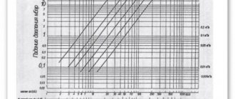
These tables show the diameters of steel and plastic pipes depending on the flow rate and speed of the coolant. If you open page 31, then in Table 1 for steel pipes the first column shows the flow rate in l/sec. In order not to make a full calculation of pipes for the heating system of a private home, you just need to select the diameter according to the flow rate, as shown in the figure below:
So, for our example, the internal passage size should be 10 mm. But since such pipes are not used in heating, we can safely accept a DN15 (15 mm) pipeline. We put it on the diagram and move on to the second section. Since the next radiator has the same power, there is no need to apply formulas; we take the previous water flow and multiply it by 2 and get 0.048 l/sec. We turn to the table again and find the closest suitable value in it. At the same time, do not forget to monitor the water flow speed v (m/sec) so that it does not exceed the specified limits (in the figures it is marked in the left column with a red circle):
As can be seen in the figure, section No. 2 is also laid with a DN15 pipe. Next, using the first formula, we find the flow rate in section No. 3:
860 x 1.5 / 20 = 65 kg/h and convert it to other units:
65 / 3600 x 0.983 = 0.018 l/sec.
Adding it to the sum of the costs of the two previous sections, we get: 0.048 + 0.018 = 0.066 l/sec and again turn to the table. Since in our example we are not calculating a gravitational system, but a pressure one, then in terms of coolant speed, a DN15 pipe is suitable this time too:
Following this path, we calculate all the areas and plot all the data on our axonometric diagram:
About determining the direction of flow
Hot-wire flowmeters have some obvious limitations.
In particular, they do not allow flow direction to be determined and are not suitable for applications requiring high sensor sensitivity. Calorimetric flowmeters, on the other hand, are designed for relatively slow gas flows with variable direction. The calorimetric sensor consists of three elements - a microheater and two sensors that measure the temperature before and after it. In the absence of flow, the heat spot emitted by the heater is motionless, therefore, to the right and left of the heater, the continuous medium has the same temperature. When a flow occurs, the heat spot “shifts” according to the direction and speed of the flow. Thus, with known pipe parameters and medium characteristics, the flow rate can be measured by the difference in temperature sensor readings.
When producing a colorimetric sensor, platinum tracks and connections between them - a microheater and two temperature sensors - are also applied to the ceramic substrate.
Since in the presence of flow the heating element is cooled, and this process is no longer used for measurements, an additional compensation temperature sensor is provided on the flow sensor.
The FS2 series sensors are built on this principle. With their help, you can determine both the direction and speed of the flow. In the range from 0 to 2.5 m/s, the sensor has a sensitivity of 0.001 m/s.
The measurement range of calorimetric sensors is limited by the very principle of its operation - at a certain flow speed, the heat spot “shifts” too far and the difference in the indicators of the right and left sensors no longer allows us to judge the flow speed.
This annoying property of calorimetric sensors is quite easy to overcome. When the flow reaches a certain speed, you can “switch” to working in hot-wire mode - start using a pair of heater + compensating temperature sensor according to the hot-wire principle already known to us.
When using a combination of two measurement methods, the magnitude of the flow velocity over most of the range is determined by a quadratic function of the voltage Uflow (lower graph), and the flow direction is determined by the voltage from a full-bridge circuit consisting of a pair of sensors and a microheater.