The conductivity of a channel determines its ability to transport gas. It is expressed in units of the volume of gas passing through a given section per unit time. The dependencies for calculating the conductivity of an element operating under various conditions are very complex and depend on the flow regime, as well as on the geometric parameters of the channel and the properties of its surface. Calculations of conductivity and gas flow under turbulent flow conditions are difficult to interpret analytically. Quantitative determination of viscous flow parameters is also difficult, since it depends not only on the shape of the channel, but also on the gas pressure. However, at those pressure ranges that occur under high vacuum conditions, the flow is molecular rather than viscous.
Publications
Added: 02/13/2017
The construction of a swimming reservoir is always accompanied by the laying of pipelines and the installation of embedded elements, such as return nozzles, bottom intakes, skimmers...
If the diameter of the pipes is smaller than required, the intake and supply of water will occur with increased friction losses, causing the pump to experience loads that can cause it to fail.
If pipes are laid with a diameter larger than required, the costs of constructing a reservoir increase unjustifiably.
How to choose the correct pipe diameter?
How to choose the correct pipe diameter?
Return nozzles, bottom intakes, skimmers, each have a connection hole of a certain diameter, which initially determines the diameter of the pipes. Typically these connections are 1 1/2″ – 2″, to which a pipe with a diameter of 50 mm is connected. If several quenching elements are connected in one line, then the common pipe must be larger in diameter than the pipes suitable for it.
The choice of pipe is also influenced by the performance of the pump, which determines the speed and amount of water pumped.
The capacity of pipes of various diameters can be determined from the following table:
Capacity of pipes of various diameters.
| Diameter, mm | Internal area section, mm2 | Capacity in m3/hour at speed | |||||
| Outer | Interior | 0.5 m/s | 0.8 m/s | 1.2 m/s | 2.0 m/s | 2.5 m/s | |
| 16 | 10 | 79 | 0,14 | 0,23 | 0,34 | 0,57 | 0,71 |
| 20 | 15 | 177 | 0,32 | 0,51 | 0,76 | 1,27 | 1,59 |
| 25 | 20 | 314 | 0,57 | 0,91 | 1,36 | 2,26 | 2,83 |
| 32 | 25 | 491 | 0,88 | 1,41 | 2,12 | 3,54 | 4,42 |
| 40 | 32 | 805 | 1,45 | 2,32 | 3,48 | 5,79 | 7,24 |
| 50 | 40 | 1257 | 2,26 | 3,62 | 5,43 | 9,05 | 11,31 |
| 63 | 50 | 1964 | 3,54 | 5,66 | 8,49 | 14,14 | 17,68 |
| 75 | 65 | 3319 | 5,97 | 9,56 | 14,34 | 23,90 | 29,87 |
| 90 | 80 | 5028 | 9,05 | 14,48 | 21,72 | 36,20 | 45,25 |
| 110 | 100 | 7857 | 14,14 | 22,63 | 33,94 | 56,57 | 70,71 |
| 125 | 110 | 9506 | 17,11 | 27,38 | 41,07 | 68,45 | 85,56 |
| 140 | 125 | 12276 | 22,10 | 35,35 | 53,03 | 88,39 | 110,48 |
| 160 | 150 | 17677 | 31,82 | 50,91 | 76,37 | 127,28 | 159,09 |
| 200 | 175 | 24061 | 43,31 | 69,29 | 103,94 | 173,24 | 216,54 |
| 225 | 200 | 31426 | 56,57 | 90,51 | 135,76 | 226,27 | 282,83 |
| 250 | 225 | 39774 | 71,59 | 114,55 | 171,82 | 286,37 | 357,96 |
| 315 | 300 | 70709 | 127,28 | 203,64 | 305,46 | 509,10 | 636,38 |
To select the turbo diameter, we need knowledge of the following quantities:
| Speed of water in the pipe by gravity | 0.5 m/s |
| Water speed in the collector pipe | 0.8 m/s |
| Average speed of water in the pipe at the pump inlet | 1.2 m/s |
| Average speed of water in the pipe at the outlet of the pump | 2.0 m/s |
| The maximum possible speed of water in the pipe | 2.5 m/s |
Let's look at the technology for selecting pipes using specific examples of piping embedded elements.
Pipe diameter for connecting return nozzles.
For example, the movement of water in the system is provided by the EcoX2-16000 pump, with a maximum capacity of 16 m3/hour.
The water is returned to the swimming bowl through 4 return nozzles - Nozzle for connecting a vacuum cleaner (connection 2″ external thread), each screwed into the wall passage with connection D 50/63.
The nozzles are located in pairs on opposite sides. We will select the required pipeline.
The water speed on the supply line is 2 m/s. The nozzles are divided into two branches of two each. Capacity for each nozzle is 4 m3/hour, for each branch – 8 m3/hour. Let's select the diameter of the common pipe, pipes for each branch and turbos for each nozzle. If the table does not have an exact match of performance for a specific flow speed, we take the closest one. According to the table it turns out:
- with a productivity of 16 m3/hour (in the table the closest value is 14.14 m3/hour) – the pipe diameter is 63 mm;
- with a productivity of 8 m3/hour (in the table the nearest value is 9.05 m3/hour) – the diameter of the turbine is 50 mm;
- with a productivity of 4 m3/hour (in the table the closest value is 3.54 m3/hour) – the pipe diameter is 32 mm.
It turns out that a pipe with a diameter of 63 mm is suitable for the general supply, a pipe with a diameter of 50 mm is suitable for each branch, and a diameter of 32 mm is suitable for each nozzle. But since the wall passage is designed to connect 50 and 63 pipes, we do not take a pipe with a diameter of 32 mm, but connect everything with a 50 mm pipe. The 63rd pipe goes to the tee, the wiring is with the 50th pipe.
Diameter of pipes for connecting skimmers.
The same pump with a capacity of 16 m3/hour takes water through skimmers. The skimmer in filtration mode usually takes from 70 to 90% of the water from the total flow that the pump sucks in, the rest falls on the bottom drain. In our case, 70% of productivity is 11.2 m3/hour. The skimmer connection is usually 1 1/2″ or 2″. The flow speed at the pump suction line is 1.2 m/s.
From the table we get:
- for this case, a pipe with a diameter of 63 mm is sufficient, but ideally 75 mm;
- in case of connecting two skimmers, we branch with the 50th pipe.
Diameter of pipes for connecting the bottom intake.
30% of the performance of the EcoX2 16000 pump is 4.8 m3/hour. According to the table, a 50 mm pipe is sufficient to connect the bottom drain. Usually, when connecting a bottom drain, they are guided by the diameter of its connection. The standard bottom drain has a 2″ connection, so choose a 63 mm pipe.
Calculation of pipe diameter.
The formula for calculating the optimal pipeline diameter is obtained from the formula for flow:
Q=(P*d2/4)*v
Where:
Q – flow rate of pumped water, m3/s d – pipeline diameter, m
v – flow velocity, m/s
P - number pi = 3.14
Hence, the calculation formula for the optimal pipeline diameter:
d=((4*Q)/(P*v))1/2
Please note that in this formula the flow rate of pumped water is expressed in m3/s. Pump capacity is usually indicated in m3/hour. In order to convert m3/hour to m3/s, you need to divide the value by 3600.
Q(m3/s)=Q(m3/hour)/3600
As an example, let's calculate the optimal pipeline diameter for a pump output of 16 m3/hour on the supply line.
Let's convert the productivity to m3/s:
Q(m3/s)=16 m3/hour/3600 = 0.0044 m3/s
The flow speed on the supply line is 2 m/s.
Substituting the values into the formula we get:
d=((4*0.0044)/(3.14*2))1/2≈0.053 (m) = 53 (mm)
It turned out that in this case the optimal internal diameter of the pipe will be 53 mm. Let's compare with the table: for the nearest productivity 14.14 m3/hour at a flow rate of 2 m/s, a pipe with an internal diameter of 50 mm is suitable.
When selecting pipes, you can use one of the methods described above; we have confirmed their equivalence with calculations.
Based on materials from the sites: waterspace com, ence-pumps ru
We recommend that you read:
Spouts for waterfalls: performance calculation, selection.
Equipment selection. Choosing a pump for an artificial reservoir
Source: https://gidrologia.ru/publikatsii/plavatelnyy-vodoem-podbor-truboprovoda-nuzhnogo-diametra.html
Hydraulic calculation of a complex gas pipeline
MINISTRY OF EDUCATION AND SCIENCE OF THE RUSSIAN FEDERATION
FSBEI HPE "VORONEZH STATE TECHNICAL UNIVERSITY"
Aviation Faculty
Department of NGOT
Specialty 130501 “Design, construction and operation of gas and oil pipelines and gas and oil storage facilities”
COURSE WORK
in the discipline "Fundamentals of the theory and design of energy systems of gas and oil pipelines and gas and oil storage facilities"
Topic: “Hydraulic calculation of a complex gas pipeline”
Completed by student gr. NGD-091 A.S. Sokolov
Head A.I. Zhitenev
Voronezh 2013
EXERCISE
for course work in the discipline “Fundamentals of the theory and design of energy systems of gas and oil pipelines and gas and oil storage facilities”
Project topic: “Hydraulic calculation of a complex gas pipeline”
Student of group NGD-091 Sokolov Alexey Sergeevich
Task No. 1
. In accordance with the assignment option (Appendix A), draw up an analytical dependence for an equivalent gas pipeline, present the conclusion of this dependence with intermediate results and detailed comments.
. Calculate the capacity of a complex gas pipeline.
. Calculate the pressure at all intermediate points and plot the dependence of the pressure on the longitudinal coordinate of the gas pipeline for each thread.
Task No. 2
1. In accordance with the task option, calculate the diameters of the pipeline system to ensure standard pressure loss values.
. Determine the initial pressure required to supply gas to all consumers in accordance with the initial data (Appendix B).
. Calculate the pressure at all intermediate points and plot the dependence of the pressure on the longitudinal coordinate of the gas pipeline for each thread.
Head A.I. Zhitenev
The task was accepted by student A.S. Sokolov
Introduction
. Hydraulic calculation of a complex high-pressure gas pipeline
.1 Determining the capacity of a complex gas pipeline
.2 Estimation of the resulting flow in the system
.3 Construction of the dependence of pressure in an equivalent gas pipeline on the longitudinal coordinate
.4 Pressure distribution across sections of the pipeline system
. Hydraulic calculation of a complex low-pressure gas pipeline
.1 Determination of pressure at network nodes
.2 Determination of the diameter of distribution network sections
.3 Bringing the diameters of network sections to standard values
.4 Determination of the dependence of pressure in the network on the longitudinal coordinate
Conclusion
Bibliography
Applications
Engineering assistance
Coolant velocity in the pipeline at: G = 0 kg/h; ρ = 1000.54 kg/m3
| Conventional passages (nominal sizes) according to GOST 28338-89 | ||||||||||||
| Dn (Du) | 10x2.2 | 15x2.8 | 20x2.8 | 25x3.2 | 32x3.2 | 40x3.5 | 50x3.5 | 65x4.0 | 80x4.0 | 90x4.0 | 100x4.5 | Legend |
| v , m/s | Pipe 20 x 2.8 GOST 3262-75 | |||||||||||
| Oventrop Metal-plastic pipe “Copipe HS” PN 10 (at 95oC), PN 16 (for cold water supply) | ||||||||||||
| Copipe HS (Oventrop) | 14×2.0 | 16×2.0 | 20×2.5 | 26×3.0 | 32×3.0 | 40×3.5 | 50×4.5 | 63×6.0 | – | – | – | Legend |
| v , m/s | – | – | – | “Copipe HS” Ø20 x 2.5 | ||||||||
| Rehau Molecular cross-linked polyethylene PN 10, t = 90oC | ||||||||||||
| RAUTITAN flex, his, pink (Rehau) | – | 16×2.2 | 20×2.8 | 25×3.5 | 32×4.4 | 40×5.5 | 50×6.9 | 63×8.6 | – | – | – | Legend |
| v , m/s | – | – | – | – | RAUTITAN flex Ø20 x 2.8 | |||||||
| Uponor Cross-linked polyethylene PE-Xa, eval PE-Xa, PN 10, t = 95oC | ||||||||||||
| Uponor PEX series S3.2 (Uponor) | – | 16×2.2 | 20×2.8 | 25×3.5 | 32×4.4 | 40×5.5 | 50×6.9 | 63×8.7 | 75×10.3 | 90×12.3 | 110×15.1 | Legend |
| v , m/s | – | Uponor PEX series S3.2 Ø20 x 2.8 | ||||||||||
| Valtec polypropylene pipe, glass fiber reinforced, PP-FIBER PN 9, t = 95oC | ||||||||||||
| Valtec PP-FIBER PN 25 (Valtec) | – | – | 20×3.4 | 25×4.2 | 32×5.4 | 40×6.7 | 50×8.3 | 63×10.5 | – | – | – | Legend |
| v , m/s | – | – | – | – | – | Valtec PP-FIBER Ø20 x 3.4 |
* Symbol: steel pipes – nominal bore x wall thickness; polymer pipes - outer diameter x wall thickness. ** Operating pressure PN is indicated at the corresponding temperature
Source: https://helpeng.ru/programs/heating/water_speed.php
Calculation of natural gas speed
The calculator allows you to determine the speed of natural gas in a pipe in accordance with GOST R 55472-2019 “Gas distribution systems. Natural gas distribution networks. Part 0. General provisions."
Enter the volumetric gas flow rate under normal conditions (Qv1)
Enter gas temperature (t1)
Enter compressibility factor (Z1)
Enter excess gas pressure (P1)
Enter the internal diameter of the gas pipeline (d1)
Calculation formula:
Speed calculation formula:
Calculation of the volume and capacity of round and profile pipes
Major home renovations or replacement of plumbing always involve the installation of pipelines. In its design, you cannot do everything “by eye”, otherwise even the most insignificant, at first glance, mistakes often lead to serious consequences. Let's look at what bandwidth is and how to calculate it.
This value reflects the amount of liquid, gas or air that can pass through a pipeline of one size or another in an hour or second.
It allows you to correctly select and install pipes, taking into account the characteristics of water intake points, be it a bathroom, dishwasher, central water supply system, etc.
The service life of the pipes, as well as the normal water pressure after they are started, depend on correctly selected plumbing fixtures.
Bandwidth is calculated using several methods:
- Physical. Depending on the purpose for which the pipeline is intended and what liquids will pass through it, the appropriate formulas are applied. Average indicators are used, for example, roughness coefficient.
- Tabular. There are graphs of approximate values that do not take into account extraneous factors: overgrowth, silt formation.
- Computer programs and online calculators. They are free and are great for calculating the operating parameters of pipes for any purpose.
The last method is the simplest and most accessible for those who want to install a water supply system with their own hands. The calculation is suitable not only for round, but also for square pipes. You don’t have to resort to complex calculations; you just need to enter the data requested by the site. You will receive a result containing the following parameters:
- total area, volume and length of the pipe;
- throughput in kg/hour and kg/sec;
- fluid flow rate in kg/hour and kg/sec.
To obtain this information, you only need to select the type of pipe, enter its diameter, length and wall thickness. You will also need to indicate the flow rate in the pipe.
What does the pipe diameter affect?
This is one of the main characteristics of the pipe system that you should pay attention to during installation. Without it, it will not be possible to determine the throughput and ensure normal fluid supply. Regardless of which material you choose: plastic or metal, the diameter will still play a decisive role.
Equations for calculating molecular flow parameters
At low pressures, intermolecular collisions occur less frequently than collisions with the wall, so the latter determine the parameters of the gas flow through the channel. The conductivity of the channel under molecular flow conditions depends on two factors:
- The speed at which molecules enter the channel.
- Probabilities of molecules passing through the system.
The first factor depends on the cross-sectional area of the entrance to the system, and the latter is determined by the subsequent series of collisions with the walls, as a result of which the molecule is ultimately moved along the channel or thrown back into the pumped vessel. Let us first consider the case of a very thin diaphragm in a plate. In this case, to determine the conductivity of the diaphragm, we are interested in its area A, and not in the properties of the channel walls. The volume of gas passing through the diaphragm - its conductivity - is:
$$C_{a}= \frac{1}{4}AV=(\frac{2}{p})^{-1} — V^{0}A, (66)$$
if the molecules have a Maxwellian velocity distribution. Conductivity values depend on molecular weight and kinetic energy. The case where collisions of molecules with the walls of the pipeline are more important than the conductivity of the hole is discussed below.
How to calculate pipe capacity
Calculating capacity is one of the most difficult tasks when laying a pipeline. In this article we will try to figure out exactly how this is done for different types of pipelines and pipe materials.
Capacity is an important parameter for any pipes, canals and other heirs of the Roman aqueduct. However, the throughput capacity is not always indicated on the pipe packaging (or on the product itself). In addition, the layout of the pipeline also determines how much liquid the pipe passes through the cross-section. How to correctly calculate the throughput of pipelines?
Methods for calculating pipeline capacity
There are several methods for calculating this parameter, each of which is suitable for a particular case. Some symbols important when determining pipe capacity:
Outer diameter is the physical size of the pipe cross-section from one edge of the outer wall to the other. In calculations it is designated as Dn or Dn. This parameter is indicated in the labeling.
Nominal diameter is the approximate value of the diameter of the internal section of the pipe, rounded to the nearest whole number. In calculations it is designated as Du or Du.
Physical methods for calculating pipe capacity
Pipe throughput values are determined using special formulas. For each type of product - for gas, water supply, sewerage - there are different calculation methods.
Tabular calculation methods
There is a table of approximate values created to make it easier to determine the capacity of pipes in apartment wiring.
In most cases, high precision is not required, so the values can be applied without complex calculations.
But this table does not take into account the decrease in throughput due to the appearance of sedimentary growths inside the pipe, which is typical for old highways.
Table 1. Pipe capacity for liquids, gas, water vapor
| Type of liquid | Speed (m/sec) |
| City water | 0,60-1,50 |
| Water pipeline | 1,50-3,00 |
| Central heating water | 2,00-3,00 |
| Pressure system water in pipeline line | 0,75-1,50 |
| Hydraulic fluid | up to 12m/sec |
| Oil pipeline line | 3,00-7,5 |
| Oil in the pressure system of the pipeline line | 0,75-1,25 |
| Steam in the heating system | 20,0-30,00 |
| Steam central piping system | 30,0-50,0 |
| Steam in a high temperature heating system | 50,0-70,00 |
| Air and gas in the central piping system | 20,0-75,00 |
There is an exact table for calculating capacity, called the Shevelev table, which takes into account the pipe material and many other factors. These tables are rarely used when laying water pipes in an apartment, but in a private house with several non-standard risers they can be useful.
Calculation using programs
Modern plumbing companies have special computer programs at their disposal to calculate pipe capacity, as well as many other similar parameters. In addition, online calculators have been developed, which, although less accurate, are free and do not require installation on a PC.
One of the stationary programs “TAScope” is a creation of Western engineers, which is shareware. In large ones, this is a domestic program that calculates pipes according to criteria that affect their operation in the regions of the Russian Federation.
In addition to hydraulic calculations, it allows you to calculate other pipeline parameters. The average price is 150,000 rubles.
How to calculate the capacity of a gas pipe
Gas is one of the most difficult materials to transport, in particular because it tends to be compressed and therefore is able to leak through the smallest gaps in pipes. There are special requirements for calculating the capacity of gas pipes (as well as for designing the gas system as a whole).
Formula for calculating the capacity of a gas pipe
The maximum throughput of gas pipelines is determined by the formula:
Qmax = 0.67 DN2 * p
where p is equal to the operating pressure in the gas pipeline system + 0.10 MPa or absolute gas pressure;
Du – conditional diameter of the pipe.
There is a complex formula for calculating the capacity of a gas pipe. It is usually not used when carrying out preliminary calculations, as well as when calculating a household gas pipeline.
Qmax = 196.386 DN2 * p/z*T
where z is the compressibility coefficient;
T is the temperature of the transported gas, K;
According to this formula, the direct dependence of the temperature of the moving medium on pressure is determined. The higher the T value, the more the gas expands and presses on the walls.
Therefore, when calculating large highways, engineers take into account possible weather conditions in the area where the pipeline runs.
If the nominal value of the DN pipe is less than the gas pressure generated at high temperatures in summer (for example, at +38 ... + 45 degrees Celsius), then damage to the line is likely. This entails the leakage of valuable raw materials and creates the possibility of an explosion in a section of the pipe.
Table of gas pipe capacities depending on pressure
There is a table for calculating gas pipeline throughputs for commonly used pipe diameters and nominal operating pressures. To determine the characteristics of a gas pipeline of non-standard sizes and pressures, engineering calculations will be required. The pressure, speed and volume of gas are also affected by the outside air temperature.
The maximum speed (W) of the gas in the table is 25 m/s, and z (compressibility coefficient) is 1. The temperature (T) is 20 degrees Celsius or 293 Kelvin.
Table 2. Gas pipeline throughput depending on pressure Pworking (MPa) Pipeline throughput (m?/h), with wgas=25m/s;z=1;T=20?C=293?KDN 50DN 80DN 100DN 150DN 200DN 300DN 400DN 5000.3 0.6 1.2 1.6 2.5 3.5 5.5 7.5 10.0
| 670 | 1715 | 2680 | 6030 | 10720 | 24120 | 42880 | 67000 |
| 1170 | 3000 | 4690 | 10550 | 18760 | 42210 | 75040 | 117000 |
| 2175 | 5570 | 8710 | 19595 | 34840 | 78390 | 139360 | 217500 |
| 2845 | 7290 | 11390 | 25625 | 45560 | 102510 | 182240 | 284500 |
| 4355 | 11145 | 17420 | 39195 | 69680 | 156780 | 278720 | 435500 |
| 6030 | 15435 | 24120 | 54270 | 96480 | 217080 | 385920 | 603000 |
| 9380 | 24010 | 37520 | 84420 | 150080 | 337680 | 600320 | 938000 |
| 12730 | 32585 | 50920 | 114570 | 203680 | 458280 | 814720 | 1273000 |
| 16915 | 43305 | 67670 | 152255 | 270680 | 609030 | 108720 | 1691500 |
Knutsen formula
The conductivity C of a section of a long pipe of length L with a variable cross-sectional area A and perimeter H was calculated by Knudsen and is:
$$C_{\Upsilon} = \frac{4}{3} \sqrt{ \frac{H( \delta)}{A^{2} L} \cdot de }. (67)$$
The following assumptions were made:
- The length of the pipeline is significantly greater than the diameter.
- The direction of movement of the rebounded molecules after colliding with the walls does not depend on the direction of their movement before the collision.
- The angular distribution of rebound molecules obeys the cosine law.
Assumption 1 assumes that the effect of the hole is negligible and the conductivity value obtained from equation (67) is related to the molecules inside the pipe away from the hole. To obtain approximate expressions for the conductivity of the entire pipe, it is necessary to include the series conductivity of the holes. Carlson gives a formula for a pipeline with perimeter H, area L and length L:
$$C_{a}=1+ \frac{3}{16} \cdot 9 \frac{LH}{A}). (58)$$
Determination of coolant flow and pipe diameters
First, each heating branch must be divided into sections, starting from the very end. The breakdown is done by water consumption, and it varies from radiator to radiator. This means that after each battery a new section begins, this is shown in the example presented above. We start from the 1st section and find the mass flow rate of the coolant in it, focusing on the power of the last heating device:
G = 860q/ ∆t, where:
- G – coolant flow, kg/h;
- q – thermal power of the radiator in the area, kW;
- Δt – temperature difference in the supply and return pipelines, usually 20 ºС.
For the first section, the coolant calculation looks like this:
860 x 2 / 20 = 86 kg/h.
The result obtained must be immediately plotted on the diagram, but for further calculations we will need it in other units - liters per second. To make a translation, you need to use the formula:
GV = G /3600ρ, where:
- GV – volumetric water flow, l/sec;
- ρ – density of water, at a temperature of 60 ºС is equal to 0.983 kg / liter.
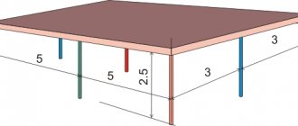
These tables show the diameters of steel and plastic pipes depending on the flow rate and speed of the coolant. If you open page 31, then in Table 1 for steel pipes the first column shows the flow rate in l/sec. In order not to make a full calculation of pipes for the heating system of a private home, you just need to select the diameter according to the flow rate, as shown in the figure below:
So, for our example, the internal passage size should be 10 mm. But since such pipes are not used in heating, we can safely accept a DN15 (15 mm) pipeline. We put it on the diagram and move on to the second section. Since the next radiator has the same power, there is no need to apply formulas; we take the previous water flow and multiply it by 2 and get 0.048 l/sec. We turn to the table again and find the closest suitable value in it. At the same time, do not forget to monitor the water flow speed v (m/sec) so that it does not exceed the specified limits (in the figures it is marked in the left column with a red circle):
As can be seen in the figure, section No. 2 is also laid with a DN15 pipe. Next, using the first formula, we find the flow rate in section No. 3:
860 x 1.5 / 20 = 65 kg/h and convert it to other units:
65 / 3600 x 0.983 = 0.018 l/sec.
Adding it to the sum of the costs of the two previous sections, we get: 0.048 + 0.018 = 0.066 l/sec and again turn to the table. Since in our example we are not calculating a gravitational system, but a pressure one, then in terms of coolant speed, a DN15 pipe is suitable this time too:
Following this path, we calculate all the areas and plot all the data on our axonometric diagram:
PC computing option
Performing calculus using a computer is the least labor-intensive - all that is required of a person is to insert the necessary data into the appropriate columns.
Therefore, hydraulic calculations are done in a few minutes, and this operation does not require a large amount of knowledge, which is necessary when using formulas.
To perform it correctly, it is necessary to take the following data from the technical specifications:
- gas density;
- coefficient of kinetic viscosity;
- gas temperature in your region.
The necessary technical conditions are obtained from the city gas department of the locality in which the gas pipeline will be built. Actually, the design of any pipeline begins with the receipt of this document, because it contains all the basic requirements for its design.
Next, the developer needs to find out the gas consumption for each device that is planned to be connected to the gas pipeline. For example, if fuel will be transported to a private house, then stoves for cooking, all kinds of heating boilers are most often used there, and their passports always contain the necessary numbers.
In addition, you will need to know the number of burners for each stove that will be connected to the pipe.
At the next stage of collecting the necessary data, information is selected about the pressure drop at the installation sites of any equipment - this could be a meter, a shut-off valve, a thermal shut-off valve, a filter, or other elements.
In this case, it is easy to find the necessary numbers - they are contained in a special table attached to the passport of each product
The designer should pay attention to the fact that the pressure drop at maximum gas consumption must be indicated
From the special table attached to the product data sheet, you can find out information about pressure loss when connecting devices to the network
At the next stage, it is recommended to find out what the blue fuel pressure will be at the insertion point. Such information may contain the technical conditions of your city gas, a previously drawn up diagram of the future gas pipeline.
If the network consists of several sections, then they must be numbered and the actual length indicated. In addition, for each one, all variable indicators should be written down separately - this is the total flow rate of any device that will be used, pressure drop, and other values.
A simultaneity coefficient will be required. It takes into account the possibility of joint work of all gas consumers connected to the network. For example, all heating equipment located in an apartment building or private house.
Such data is used by a hydraulic calculation program to determine the maximum load on any section or entire gas pipeline.
For each individual apartment or house, the specified coefficient does not need to be calculated, since its values are known and indicated in the table below:
A table with simultaneity coefficients, data from which is used for any type of calculation. It is enough to select the column corresponding to a specific household appliance and take the desired number
If at some facility it is planned to use more than two heating boilers, furnaces, and storage tank water heaters, then the simultaneity indicator will always be 0.85. This is what you will need to indicate in the corresponding column used for the calculation of the program.
Next, you should indicate the diameter of the pipes, and you will also need their roughness coefficients, which will be used in the construction of the pipeline. These values are standard and can be easily found in the Rulebook.
Calculation of flow in a limited area
If the gas pipeline consists of separate sections, then the calculation of the total flow rate for each of them will have to be performed separately. But this is not difficult, since the calculations will require already known numbers.
Defining data using the program
Knowing the initial indicators, having access to the simultaneity table and technical data sheets of stoves and boilers, you can begin the calculation.
To do this, perform the following steps (the example is given for a low-pressure intra-house gas pipeline):
- The number of boilers is multiplied by the productivity of each of them.
- The resulting value is multiplied by the simultaneity coefficient specified using a special table for this type of consumer.
- The number of stoves intended for cooking is multiplied by the productivity of each of them.
- The value obtained after the previous operation is multiplied by the simultaneity coefficient taken from a special table.
- The resulting amounts for boilers and stoves are summed up.
Similar manipulations are carried out for all sections of the gas pipeline. The obtained data is entered into the appropriate columns of the program with which the calculations are performed. The electronics does everything else itself.
Calculation using formulas
This type of hydraulic calculation is similar to that described above, that is, the same data will be required, but the procedure will be lengthy. Since everything will have to be done manually, in addition, the designer will need to carry out a number of intermediate operations in order to use the obtained values for the final calculation.
You will also have to devote quite a lot of time to understand many concepts and issues that a person does not encounter when using a special program. The validity of the above can be verified by familiarizing yourself with the formulas to be used.
Calculation using formulas is complex and therefore not accessible to everyone. The picture shows formulas for calculating the pressure drop in the high, medium and low pressure network and the coefficient of hydraulic friction
In the application of formulas, as in the case of hydraulic calculations using a special program, there are features for low, medium and, of course, high pressure gas pipelines. And it’s worth remembering, since a mistake is always fraught with significant financial costs.
Calculations using nomograms
Any special nomogram is a table that shows a number of values, by studying which you can obtain the desired indicators without performing calculations. In the case of hydraulic calculations, the diameter of the pipe and the thickness of its walls.
Nomograms for calculation are a simple way to obtain the necessary information. It is enough to refer to the lines that meet the specified network characteristics
There are separate nomograms for polyethylene and steel products. When calculating them, standard data were used, for example, the roughness of the internal walls. Therefore, you don’t have to worry about the correctness of the information.
Influence of pipe material on calculation
For the construction of gas pipelines, you can use pipes made only from certain materials: steel, polyethylene. In some cases, copper products are used. Metal-plastic structures will soon be widely used.
Each pipe has a roughness, which leads to linear resistance, which affects the process of gas movement. Moreover, this figure is significantly higher for steel products than for plastic ones.
Today, the necessary information can only be obtained for steel and polyethylene pipes. As a result, design and hydraulic calculations can only be carried out taking into account their characteristics, which is required by the relevant Code of Practice. The document also contains the data necessary for the calculation.
The roughness coefficient is always equal to the following values:
- for all polyethylene pipes, regardless of whether they are new or not, - 0.007 cm;
- for already used steel products - 0.1 cm;
- for new steel structures - 0.01 cm.
For any other types of pipes this indicator is not indicated in the Code of Practice. Therefore, they should not be used for the construction of a new gas pipeline, since Gorgaz specialists may require adjustments to be made. And these are again additional costs.
Hydraulic calculation of a gas pipeline: methods and methods of calculation + calculation example
For safe and trouble-free operation of the gas supply, it must be designed and calculated
It is important to perfectly select pipes for mains of all types of pressure, ensuring a stable supply of gas to devices
To ensure that the selection of pipes, fittings and equipment is as accurate as possible, a hydraulic calculation of the pipeline is performed. How to make it? Admit it, you are not too knowledgeable about this issue, let's figure it out.
We offer you to familiarize yourself with carefully selected and thoroughly processed information about options for producing hydraulic calculations for gas pipeline systems. Using the data we present will ensure that the devices are supplied with blue fuel with the required pressure parameters. Carefully verified data is based on the regulations of regulatory documentation.
The article describes in great detail the principles and schemes for performing calculations. An example of performing calculations is given. Graphic applications and video instructions are used as a useful informative addition.
Rules for performing calculations
It was stated above that the procedure for any hydraulic calculation is regulated by the profile Code of Rules with the number 42-101–2003.
The document indicates that the main way to perform the calculation is to use a computer for this purpose with special programs that allow you to calculate the planned pressure loss between sections of the future gas pipeline or the required pipe diameter.
Any hydraulic calculation is performed after creating a calculation diagram that includes the main indicators. Moreover, the user enters known data into the appropriate columns
If there are no such programs or a person believes that their use is inappropriate, then other methods permitted by the Code of Rules can be used.
Which include:
- calculation using the formulas given in the SP is the most complex method of calculation;
- calculation using so-called nomograms is a simpler option than using formulas, because you don’t have to make any calculations, because the necessary data is indicated in a special table and given in the Code of Rules, and you just need to select them.
Any of the calculation methods leads to the same results. Therefore, the newly built gas pipeline will be able to ensure timely, uninterrupted supply of the planned amount of fuel even during the hours of its maximum use.