Angle steel is the most popular type of shaped steel. According to the production method, it is divided into hot-rolled and bent. Source materials: ordinary quality carbon steel St3 ps/sp (for ordinary use), high-quality, low-alloy steel 09G2S, 17G1S, 10HSND, 15 KHSND (for products used under high loads, in difficult temperature conditions, in contact with aggressive environments).
Calculator
| Calculation example |
Related calculators:
- Collection of loads on floor beams online.
- Calculation of a rectangular pipe
- Square pipe calculation
- I-beam calculation
- Channel calculation
- Calculation of a wooden beam
Meet the reinforced corner!
The fastening angle is the simplest and most reliable fastening element. Using it, you can attach a shelf to the wall, form a bed frame, install a roof rafter system, construct a stair lift, secure a system of utility pipes, and form a box for sheathing with plasterboard sheets.
In any of these options, if the structure is subject to heavy loads, an important task is to ensure reliability and strength! Alternatively, you can install the corners in a continuous sequence; then this will affect both the cost of the work and the appearance of the connection node. To provide increased load-bearing capacity, a stiffening rib has been added to the design of the corner. This element runs in the middle of the fastener along both of its walls.
The reinforced fastening angle is an improved version of the standard fastening angle. The presence of a stiffener corner in the design allows it to be used when connecting load-bearing wooden structures. Such elements usually have large dimensions and weight in the rafter system, and require more reliable fastening.
Instructions for the calculator
Please note that in non-integer numbers it is necessary to put a period, not a comma, that is, for example, 5.7 m, not 5.7. Also, if something is not clear, ask your questions through the comment form located at the very bottom.
Initial data
Calculation scheme:
Span length (L) - the distance between two supports or from a rigid embedment to the edge of the console.
Distances (A and B) - distances from the supports to the place of application of forces. In the case of the 3rd scheme - the distance from the support to the edge of the console.
Standard and design loads are loads that act on the angle, expressed in kg/m or kg.
F max is the maximum permissible deflection for a beam used in a particular structure. Can be found in Table E.1 of Appendix E of SNiPa 2.01.07-85* (SP 20.13330.2011) “Loads and Impacts”. This indicator for the most common case is presented in Table 1.
Number of corners - if you are going to use two paired corners as a beam, then you need to choose “two”, otherwise “one”.
Steel characteristics:
Design resistance (Ry) - selected depending on the steel grade. But most often designers accept Ry = 210 MPa. For the rest, see Table 2.
Angle dimensions - select the expected size of an equal and (or) unequal angle.
Location - selected for the unequal corner depending on how it will work.
By X - if the load falls on a short shelf.
Along Y - if the load falls on a long shelf.
Characteristics of steel angle
The product is manufactured with high precision grade “A” and regular precision grade “B”. They can be of limited length, unmeasured, multiple and measured. The finished profile allows a maximum length of 12 meters. Unequal ones are longer. Advantages of a metal product:
- possible use in places with free space for equipment and people;
- resistance to corrosion and weathering;
- high quality, strength and rigidity;
- long service life;
- versatility;
- no twisting around the longitudinal axis.
Methods for calculating a metal corner, weight table, product features
Angle steel is the most popular type of shaped steel. According to the production method, it is divided into hot-rolled and bent. Source materials: ordinary quality carbon steel St3 ps/sp (for ordinary use), high-quality, low-alloy steel 09G2S, 17G1S, 10HSND, 15 KHSND (for products used under high loads, in difficult temperature conditions, in contact with aggressive environments).
Characteristics of hot rolled metal angle
Equal-flanged hot-rolled steel angles are produced in accordance with GOST 8509-93 from a square, which is the original workpiece. The most widely used angular profile of normal accuracy is “B”; for critical structures, high-precision products “A” are used. The shelf dimensions, according to the standard, are from 20 to 250 mm.
The range of unequal corners is determined by GOST 8510-86. The smallest shelf sizes are 16 and 25 mm, the maximum are 125 and 200 mm. These products are used to create structures of complex shapes, such as arches.
Hot-rolled products are characterized by high strength, which allows them to be used in structures designed to operate under high load conditions. In the production of corner profiles, carbon steel of ordinary quality and high quality is widely used. Products made from low-alloy steels are used to create critical structures of housings, frames and other parts of agricultural machinery, locomotives, cars, large-sized construction machines and mechanisms. Products made from this profile can maintain performance characteristics over a wide temperature range - from -70° to +70°C, with serious daily and seasonal temperature changes.
Along with the types, there are four load schemes:
- Hinge-Hinge
- Seal-Hinge
- Seal-Seal"
- Free end
Our online calculator allows you to make calculations by combining all types of beams, types and load patterns, while absolutely eliminating the possibility of making an error during the calculation process. Usually wooden beams, as well as metal ones, are calculated. In the process of calculating the indicator, the sum of forces acting on the beam, which are directed perpendicular to the structure, is determined. The calculation of a wooden beam for deflection is carried out taking into account the material, i.e. take into account the type of wood, its flexibility and many other parameters; it is also important to take into account the cross-sectional shape of the beam and what type of load is placed on the beam. Compared with the calculation of a wooden beam, the calculation of a metal beam for deflection is significantly different, since important attention is paid to the type of connection: electric welding, rivets, bolts and other types of connections.
All the nuances listed above make it possible to understand that calculating a beam for deflection is an extremely important stage in the process of constructing any object. The reliability, durability and integrity of the entire structure depend on it. Our calculator will allow you to quickly and accurately make extremely accurate calculations.
Square pillars still have a number of disadvantages
- the design turns out to be very labor-intensive, since it is necessary not only to ensure the vertical position of the pillars, but also to ensure that one of their faces is in the plane of the fence;
- since the weight of a square pipe is 30% more than a round one, its cost is 35% more expensive;
- the weld seam, present in pipes with a square cross-section along their entire length, serves as a place for the active development of corrosion processes, which are not hindered even by painting.
Therefore, we recommend that for fence posts you choose posts from used tubing pipes with a round cross-section and with the greatest possible wall thickness. It would be great if these pipes were made using seamless technology.
The joists are attached to the round posts in an overlapping manner using two short seams along the top and bottom edges of the joists. Such connections are not blown out, last a long time, and can be protected from corrosion with paint. The weld in this case is very strong, and the load-bearing structure of the fence has maximum rigidity due to the fact that the logs do not have to be cut. In addition, individual pillars do not protrude from the ground in this case.
Calculation of angle for deflection and bending
This online calculator is designed to allow you to easily and quickly select the dimensions of the corner depending on the load on it. Its peculiarity is that on one page it is possible to compare equal (GOST 8509-93) and unequal (GOST 8510-86) corners. The latter, in turn, can be selected depending on its location in space, i.e. depending on how it will be oriented relative to the load.
The corners are calculated for bending and deflection (in terms of strength and deformation) for the following design schemes:
- Type 1 – single-span simply supported beam with a uniformly distributed load. Example: a corner lintel that carries floor slabs and a low masonry height. (For more information on calculating corner jumpers, see this calculator).
- Type 2 – cantilever beam with rigid embedding and uniformly distributed load. Example: a reinforced concrete canopy made using an angle that is rigidly (using stiffeners that limit any turns) welded to a reinforced concrete wall.
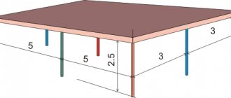
- Type 3 – single-span hinged beam with a cantilever with a uniformly distributed load. Example: the same canopy as in the previous diagram, only here the corner is inserted into the wall on one side and rests on a brace on the other (blue in the picture).
- Type 4 – single-span simply supported beam with one concentrated force. Example: a lintel on which one floor beam rests.
- Type 5 is a single-span simply supported beam with two concentrated forces. Example: a bridge supported by two concentrated forces.
- Type 6 – cantilever beam with one concentrated force. Example: the canopy of a house with a brick wall on it, built in an African republic (where it never snows) according to the imagination of an African architect. The corners of this canopy are firmly embedded in the wall, as described in the second diagram.
Note: the calculated angle in the example drawings is colored red.
Calculation of angle for deflection and bending
Using this calculator, you can not only easily calculate the angle for deflection and bending, but also select the optimal one from equal and unequal angles.
constructing diagrams in beams
Design diagram No. 274130
Why not free?
– The site was created solely on the enthusiasm of the author, and so that this enthusiasm does not fade away, I would like to back it up with at least some kind of material encouragement. In addition, the increased number of users forced us to switch to paid hosting.
And your site will not steal my card number, passwords, etc.
- This is impossible! After you click “Translate”, you will be redirected to the Yandex page (you can check it in the address bar), and all further operations will be performed on the Yandex service, so nothing threatens you from the site.
Hard seal
Articulated support
Mortise hinge
Concentrated force F
Concentrated moment M
Distributed load
Beam calculator - calculation for different types of structures
Beams in a house usually belong to the rafter system or floor, and in order to get a reliable structure that can be operated without any fear, you need to use a beam calculator .
What is the beam calculator based on?
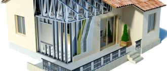
When the walls have already been brought under the second floor or under the roof, it is necessary to make a ceiling, in the second case smoothly turning into rafters. In this case, the materials must be selected so that the load on the brick or log walls does not exceed the permissible value, and the strength of the structure is at the proper level. Therefore, if you are going to use wood, you need to choose the right beams from it and make calculations to determine the required thickness and sufficient length.
Beam calculator
The subsidence or partial destruction of the ceiling can be due to various reasons, for example, too large a step between the lags, deflection of the cross members, too small their cross-sectional area or defects in the structure. To eliminate possible excesses, you should find out the expected load on the floor, be it basement or interfloor, and then use a beam calculator, taking into account their own weight. The latter can change in concrete lintels, the weight of which depends on the density of the reinforcement; for wood and metal, with a certain geometry, the weight is constant. The exception is damp wood, which is not used in construction work without first drying it.
Beam systems in floors and rafter structures are loaded by forces acting on section bending, torsion, and lengthwise deflection . For rafters, it is also necessary to provide for snow and wind loads, which also create certain forces applied to the beams. You also need to accurately determine the required step between the jumpers, since too many crossbars will lead to excess weight of the floor (or roof), and too little, as mentioned above, will weaken the structure.
How to calculate the load on a floor beam
The distance between the walls is called a span, and there are two of them in the room, and one span will necessarily be smaller than the other if the shape of the room is not square. Interfloor or attic floor lintels should be laid along a shorter span, the optimal length of which is from 3 to 4 meters. Larger spacing may require non-standard sized beams, which will result in some unsteadiness of the deck. The best solution in this case would be to use metal crossbars.
Regarding the cross-section of a wooden beam, there is a certain standard that requires that the sides of the beam have a ratio of 7:5, that is, the height is divided into 7 parts, and 5 of them must make up the width of the profile. In this case, deformation of the section is excluded, but if you deviate from the above indicators, then if the width exceeds the height, you will get a deflection, or, if the opposite discrepancy occurs, a bend to the side. To prevent this from happening due to the excessive length of the beam, you need to know how to calculate the load on the beam. In particular, the permissible deflection is calculated from the ratio to the length of the lintel as 1:200, that is, it should be 2 centimeters per 4 meters.
To prevent the beam from sagging under the weight of logs and flooring, as well as interior items, you can grind it from below a few centimeters, giving it the shape of an arch; in this case, its height should have an appropriate margin.
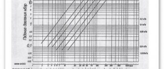
Now let's turn to the formulas. The same deflection mentioned earlier is calculated as follows: fnor = L/200, where L is the span length, and 200 is the permissible distance in centimeters for each unit of beam subsidence. For a reinforced concrete beam, the distributed load q on which is usually equal to 400 kg/m 2, the calculation of the maximum bending moment is performed using the formula Mmax = (q · L 2)/8. In this case, the amount of reinforcement and its weight is determined according to the following table:
Cross-sectional areas and mass of reinforcing bars
Beam calculator - calculation for different types of structures
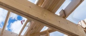
Security in the house is not only video surveillance, but also strong walls and ceilings, which means that during construction it’s a good idea to use a beam calculator