Ulysses
20247 0 3
Ulysse August 27, 2016Specialization: road construction, finishing works.
The frame of the house in this example is made of profile pipe
Usually, when pipes are used in everyday life (as a frame or supporting parts of some structure), no attention is paid to issues of stability and strength. We know that the load will be small and strength calculations will not be needed. But knowledge of the methodology for assessing strength and stability will definitely not be superfluous; after all, it is better to be firmly confident in the reliability of the building than to rely on a lucky chance.
In what cases is strength and stability calculation needed?
Calculation of strength and stability is most often needed by construction organizations, because they need to justify the decision made, and it is impossible to make a large reserve due to the rise in cost of the final structure. Of course, no one calculates complex structures manually; you can use the same SCAD or LIRA CAD for calculations, but simple structures can be calculated with your own hands.
Instead of manual calculations, you can use various online calculators; as a rule, they present several simple calculation schemes and give you the opportunity to select a profile (not only a pipe, but also I-beams, channels). By specifying the load and specifying the geometric characteristics, a person receives maximum deflections and values of transverse force and bending moment in a dangerous section.
An example of a simple calculator for calculations
In principle, if you are building a simple canopy over a porch or making a stair railing at home from a profile pipe, then you can do without calculations at all. But it’s better to spend a couple of minutes and figure out whether the load-bearing capacity of your frame for a canopy or fence posts will be sufficient.
If you strictly follow the calculation rules, then according to SP 20.13330.2012 you must first determine the following loads:
- constant - this means the structure’s own weight and other types of loads that will have an impact throughout its entire service life;
- temporary long-term – we are talking about a long-term impact, but over time this load may disappear. For example, the weight of equipment, furniture;
- short-term - as an example, we can cite the weight of the snow cover on the roof/canopy above the porch, wind exposure, etc.;
- special - those that are impossible to predict, it could be an earthquake, or racks made of pipes by a machine.
According to the same standard, the design of pipelines for strength and stability is carried out taking into account the most unfavorable combination of loads of all possible. At the same time, such pipeline parameters as the wall thickness of the pipe itself and adapters, tees, and plugs are determined. The calculation differs depending on whether the pipeline runs underground or above ground.
There’s definitely no point in complicating your life in everyday life. If you are planning a simple building (a frame for a fence or a canopy, a gazebo will be built from pipes), then there is no point in manually calculating the load-bearing capacity, the load will still be negligible and the safety margin will be sufficient. Even a 40x50 mm pipe is enough to build a canopy or stands for a future European fence.
The photo shows a fairly simple design. Here you can do without calculations
To assess the load-bearing capacity, you can use ready-made tables, which, depending on the span length, indicate the maximum load that the pipe can withstand. In this case, the pipeline’s own weight is already taken into account, and the load is presented in the form of a concentrated force applied along the center of the span.
For example, a 40x40 pipe with a wall thickness of 2 mm over a span of 1 m can withstand a load of 709 kg, but when the span increases to 6 m, the maximum permissible load is reduced to 5 kg .
Permissible load depending on span length
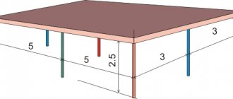
Hence the first important note - do not make the spans too large, this reduces the permissible load on it. If you need to cover a large distance, it is better to install a pair of racks, you will get an increase in the permissible load on the beam.
Is it necessary to calculate the load?
The popularity of profile pipes is explained by their low cost, low weight, and high bending strength.
. When choosing rolled products with a rectangular or square cross-section, most customers understand the importance of calculating the load on the profile pipe. The correspondence of the linear dimensions of the profiles to the possible mechanical force on the part is taken into account.
What will happen if we do not take into account the possible impact of gravity on the structure?
You can’t even think about this, since when exposed to the maximum permissible weight,
2 options
:
- irreversible bending of the pipe, as it will lose its elasticity;
- destruction of the entire structure, which is fraught with negative consequences.
Calculation is not always required
If you decide to use a profile pipe to build a gate, fence, or railing, then it is not necessary to carry out bending calculations, since the load on such systems is minimal.
Classification and calculation of the simplest structures
In principle, you can create a structure of any complexity and configuration from pipes, but in everyday life, standard designs are most often used. For example, a diagram of a beam with rigid pinching at one end can be used as a model for the support of a future fence post or support for a canopy. So, having considered the calculation of 4-5 standard schemes, we can assume that most problems in private construction can be solved.
Scope of pipe depending on class
When studying the range of rolled products, you may come across such terms as pipe strength group, strength class, quality class, etc. All these indicators allow you to immediately find out the purpose of the product and a number of its characteristics.
Important! Everything that will be discussed below concerns metal pipes. In the case of PVC and polypropylene pipes, of course, it is also possible to determine strength and stability, but given the relatively mild conditions of their operation, there is no point in giving such a classification.
Since metal pipes operate in pressure mode, hydraulic shocks may periodically occur; constancy of dimensions and compliance with operational loads are of particular importance.
For example, according to quality groups, 2 types of pipelines can be distinguished:
- class A – mechanical and geometric parameters are controlled;
- class D – resistance to hydraulic shocks is also taken into account.
It is also possible to divide rolled pipe into classes depending on the purpose, in this case:
- Class 1 - indicates that rental can be used to organize water and gas supply;
- Class 2 – indicates increased resistance to pressure and water hammer. Such rolled products are already suitable, for example, for the construction of a highway.
Strength classification
Pipe strength classes are given depending on the temporary tensile strength of the wall metal. By the marking you can immediately judge the strength of the pipeline, for example, the designation K64 means the following: the letter K indicates that we are talking about a strength class, the number indicates the temporary tensile strength (units kg∙s/mm2).
The minimum strength indicator is 34 kg∙s/mm2, and the maximum is 65 kg∙s/mm2. In this case, the strength class of the pipe is selected based not only on the maximum load on the metal, the operating conditions are also taken into account.
There are several standards that describe the strength requirements for pipes, for example, for rolled products that are used in the construction of gas and oil pipelines, GOST 20295-85 is relevant.
Pipe marking examples
In addition to classification by strength, a division is also introduced depending on the type of pipe:
- type 1 – straight-seam (resistance welding with high-frequency current is used), diameter is up to 426 mm;
- type 2 – spiral suture;
- type 3 – straight-seam.
Pipes may also differ in steel composition; high-strength rolled products are produced from low-alloy steel. Carbon steel is used for the production of rolled products with strength classes K34 - K42.
Carbon content
As for the physical characteristics, for strength class K34, the tensile strength is 33.3 kg∙s/mm2, the yield strength is at least 20.6 kg∙s/mm2, and the relative elongation is no more than 24%. For the stronger K60 pipe, these figures are already 58.8 kg∙s/mm2, 41.2 kg∙s/mm2 and 16%, respectively.
Characteristics of pipes by strength class
Allowable bend radii based on material strength
The bending radius of the profile depends on the external section DN, the thickness of the material, its density and flexibility.
State standards establish minimum bending radii for profiled pipes. Their permissible size is largely determined by the way the part is bent.
- If the bend is made by heating the workpiece, or by filling it with sand, the bend radius must be at least 3.5 DN.
- Bending on bending equipment without heating is possible with a minimum radius of 4 DN.
- If the process uses furnace heating, a value of 2.5 DN is allowed.
- An important condition for bending is the thinning of the walls of the product in the area of operation by no more than 15%.
Calculation of standard circuits
In private construction, complex pipe structures are not used. They are simply too difficult to create, and there is really no need for them in the grand scheme of things. So when building, you are unlikely to encounter anything more complex than a triangular truss (for a rafter system).
In any case, all calculations can be done with your own hands, if you have not yet forgotten the basics of strength materials and structural mechanics.
Console calculation
The console is an ordinary beam, rigidly fixed on one side. An example is a fence post or a piece of pipe that you attached to the wall of the house to create a canopy over the porch.
In principle, the load can be anything, it can be:
- a single force applied either to the edge of the console or somewhere in the span;
- load distributed evenly along the entire length (or on a separate section of the beam);
- load, the intensity of which varies according to some law;
- Also, pairs of forces can act on the console, causing the beam to bend.
In everyday life, most often you have to deal with the load of a beam with a single force and a uniformly distributed load (for example, wind load). In the case of a uniformly distributed load, the maximum bending moment will be observed directly at the rigid embedment, and its value can be determined by the formula
M= ql22;
where M is the bending moment;
q – intensity of uniformly distributed load;
l is the length of the beam.
In the case of a concentrated force applied to the console, there is nothing to calculate - in order to find out the maximum moment in the beam, it is enough to multiply the magnitude of the force by the arm, i.e. the formula will take the form
M= F∙l.
Maximum moments when the console is loaded with concentrated and distributed load
All these calculations are needed for the sole purpose of checking whether the strength of the beam will be sufficient under operating loads; any instruction requires this. When calculating, it is necessary that the obtained value be lower than the reference value of the tensile strength; it is desirable that there be a margin of at least 15-20%; nevertheless, it is difficult to provide for all types of loads.
To determine the maximum stress in a dangerous section, a formula of the form is used
σ= MmaxW;
where σ is the stress in the dangerous section;
Mmax – maximum bending moment;
W is the sectional moment of resistance, a reference value, although it can be calculated manually, it is better to simply look at its value in the assortment.
Beam on two supports
Another simplest option for using a pipe is as a light and durable beam. For example, for installing floors in a house or when building a gazebo. There may also be several loading options here; we will focus only on the simplest ones.
The beam is loaded with a concentrated force in the center
Concentrated force at the center of the span is the simplest option for loading a beam. In this case, the dangerous section will be located directly below the point of application of the force, and the magnitude of the bending moment can be determined using the formula.
M= F∙l4.
A slightly more complex option is a uniformly distributed load (for example, the dead weight of the floor). In this case, the maximum bending moment will be equal to
M= ql28.
The beam is loaded with a uniformly distributed load
In the case of a beam on 2 supports, its rigidity also becomes important, that is, the maximum movement under load, in order for the rigidity condition to be met, it is necessary that the deflection does not exceed the permissible value (set as part of the beam span length, for example, l/300).
When a concentrated force acts on a beam, the maximum deflection will be located under the point of application of the force, that is, in the center.
The calculation formula looks like
f=Fl348EI.
where E is the elastic modulus of the material;
I – moment of inertia.
The modulus of elasticity is a reference value; for steel, for example, it is equal to 2∙105 MPa, and the moment of inertia is indicated in the assortment for each pipe size, so there is no need to calculate it separately and even a humanist can do the calculation with his own hands.
Round pipe range
For a uniformly distributed load applied along the entire length of the beam, the maximum displacement will be observed in the center. It can be determined by the formula
f= 5ql4384EI.
Most often, if all conditions are met when calculating strength and there is a margin of at least 10%, then there are no problems with rigidity. But occasionally there may be cases when the strength is sufficient, but the deflection exceeds the permissible value. In this case, we simply increase the cross-section, that is, we take the next pipe in the range and repeat the calculation until the condition is met.
Statically indeterminate structures
In principle, working with such schemes is also not difficult, but you need at least minimal knowledge of strength materials and structural mechanics. Statically indeterminate schemes are good because they allow you to use material more economically, but their downside is that the calculation becomes more complicated.
The simplest diagrams of statically insurmountable beams
The simplest example is to imagine a span of 6 meters long, you need to cover it with one beam. Options for solving problem 2:
- just lay a long beam with the largest possible cross-section. But due to its own weight alone, its strength resource will be almost completely selected, and the cost of such a solution will be considerable;
- install a pair of racks in the span, the system will become statically indeterminate, but the permissible load on the beam will increase by an order of magnitude. As a result, you can take a smaller cross-section and save on material without reducing strength and rigidity.
External surface area
When installing different pipelines, they may require insulation, waterproofing, painting, etc. To do this, it is necessary to determine the area of the pipeline, which will allow you to calculate the amount of material. To perform this calculation, you need to multiply the circumference of the outer section by the length of the pipe.
The formula for determining a circle is as follows - L=πD. We denote the length of the pipe section as H.
In this case, the area of the outer circumference of the pipe will look like this – St=πDH m2, where:
- St is the surface area of the pipe, which is measured in square meters.
- π – The number “pi”, which is always equal to 3.14;
- D—outer diameter;
- H - as mentioned above, denotes the length of the pipe in meters.
For example, there is a pipe 5 meters long and 30 cm in diameter. Its surface area is St=πDH=3.14*0.3*5=4.71 square meters.
Based on the above formulas, you can also calculate the volume of the pipeline and the area of its internal walls. To do this, you just need to change the value of the external diameter in the calculations to the value of the internal one. All these parameters may be required when installing a household pipeline.