For metals, the yield strength is specified as the stress that the material can withstand.
The pipe will bend, but most likely will not break yet. But glass and carbon fiber will break.
You can't trust calculations! Consider it as purely indicative.
Always consider the safety factor
.
If the pipe is used or there are stress concentrators (holes, crimps, bushings, welding, etc.), destruction can occur under a load several times less than can be expected! The properties of glass and carbon fiber reinforced plastic also strongly depend on the properties of the fiber and manufacturing technology.
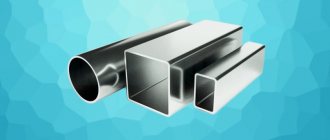
Profile pipes are common in industrial and private construction. They are used to construct outbuildings, garages, greenhouses, and gazebos. The designs can be either classically rectangular or ornate. Therefore, it is important to correctly calculate the pipe for bending. This will maintain its shape and ensure the structure’s strength and durability.
Characteristics of metal for bending
Any metal has its own point of resistance, that is, the maximum and minimum load that it can withstand.
If you put too much pressure on the metal, it can cause deformation, unnecessary deflections or breaks in the profile. When calculating pipe bending, it is necessary to take into account such important characteristics as metal density, dimensions and diameter of profile or round pipes, as well as a number of other parameters. Thus, it will be possible to predict how effective the use of a particular material will be under environmental conditions.
Please note that stress will arise not only directly at the bending point of the profile pipe, but also in areas remote from the center of the bend. The highest shear stress will be observed precisely in the area of the central axis of the bend.
During pipe bending, the inner layer of metal is compressed and becomes smaller, while the outer layer, on the contrary, increases due to stretching. But the central layer of metal remains unchanged, maintaining the original parameters, thereby ensuring the strength of the pipe.
What load acts on the profile pipe?
External mechanical forces act on the profiled pipe: the weight of structures, the weight of snow, wind influences, etc.
Moreover, each product has a maximum resistance value. For example, an indicator of the load that a profile can withstand in bending. When the maximum value is reached, the structure loses strength and begins to deform until it breaks.
This value must be accurately determined at the design stage of installation work. It is calculated by calculation methods, using reference information, the purpose of which is to help determine the necessary profile parameters: cross-section, metal thickness. The initial data in this case are the strength characteristics of the material and the types of upcoming loads.
Perform bending calculations
Calculating a round pipe for bending is required in order to determine the maximum permissible stress level for each specific section of the pipe.
Each material has its own normal stress value, which does not have any effect on the product itself. To obtain correct calculations, they must be carried out using a special formula. Particular attention should be paid to ensuring that indicators remain within the maximum permitted values. According to Hooke's law, the resulting elastic force is directly proportional to the deformation.
When calculating the amount of bending, you must additionally use the following stress formula: M/W, where M is the amount of bending along the axis experiencing the force, and W is the amount of resistance of this axis at the point of bending.
Load design diagrams
The process of calculating any profile begins with the selection of a design schematic model.
Before starting calculations, collect the load that will act on the floor.
Then a diagram is drawn taking into account the loading pattern and beam supports.
Next, using the specified parameters and information from the assortment tables given in GOSTs, the corresponding calculations are made.
For their simplicity and efficiency, you can use online calculators that are equipped with programs with ready-made formulas.
Bending technology
During the bending process, certain stress indicators arise in the metal. Tensile stress is generated on the outside, and compressive stress is generated on the inside. At the moment of such interactions, the bending of the axis changes.
During bending, the cross-sectional shape of the bent segment changes. As a result, the ring-shaped profile changes its shape to oval. The clearest oval can be observed in the middle of the deflection. The deformation decreases at the beginning and end of the deflection.
For pipes with a diameter of no more than 20 mm, the ovality in the section subject to deformation should be no more than 15%. And for pipes with diameters equal to or greater than 20 mm - 12.5%.
It is worth noting that folds may appear from inside the bend, where compression deformation occurs. This fact, as a rule, negatively affects the correct operation of the system, since folds reduce the permeability of the pipes, increase the amount of hydraulic resistance and the level of clogging.
Maximum loads
To select the correct pipe for use, you need to know the maximum weight that the beam or support must support in a given location.
This quantity is expressed as a concentrated force applied at the center of the span.
Under the pressure of the specified force, the beam will bend, but after the end of the impact it will return to its previous state (in the photo). Exceeding the highest value will break the carrier.
In everyday practice, a distributed load is often encountered, uniformly affecting the entire length of the beam.
This suggests the conclusion that spans should not be too large. Installing a powerful beam can cover its advantages at the cost of the issue and the overall weight of the structure. It makes more sense to install additional supports, which allows you to increase the permissible weight on the floor.
To determine the magnitude of the maximum loads, you can use various reference data on the Internet.
Pipe bending radius limits
Guided by state standards, pipes must have a minimum bending radius (for more details: “What pipe bending radius can be obtained using different types of pipe benders”). When bending a pipe filled with sand by heating, the external cross-section of the pipe must be at least 3.5 DN. When changing the shape of a pipe on a pipe bending machine without using heat - more than 4DN.
When heated with a gas burner or in an oven, in order for the folds to form halfway, the value should be 2.5 DN. In case of need to obtain a strong bend, for example for systems with bent sewer outlets, which are manufactured by hot drawing or stamping - more than 1 DN.
The pipe may have a smaller bend value. However, this can only be allowed if the pipes were manufactured using a technology where their walls are thinned by 15% of the total thickness.
All calculations of pipe bending strength must be carried out with maximum responsibility.
Is it possible to do without calculations?
Simple household structures (light fences) are made with a margin of safety, avoiding calculations. The costs of such structures will be small, and there is no point in bothering yourself with labor-intensive calculations.
However, more complex structures (canopies, terraces, greenhouses) that can collapse or break under a gust of wind, snow, or the weight of basic equipment already require a simple calculation definition.
Formulas and other data for obtaining calculations
To carry out deflection calculations, we find out the length of the part.
You can get it using the following formula:
L=0.0175∙R∙α+l, where
- R – bending radius, measured in millimeters;
- α – angle;
- I – an even segment of 100/300, necessary for gripping the product (when operating with a tool).
When making calculations for a profile pipe, you need to take into account the size of the element to be bent.
To do this, you need to carry out calculations using the following formula:
А=π∙α/180(R+DH/2), where
- π – 3.14;
- α – bending angle;
- R – radius (measured in millimeters);
- DH is the outer section of the pipe.
The minimum permissible degrees for bending copper and brass pipes can be found in the corresponding tables. All data corresponds to GOSTs No. 494/90 and No. 617/90. Additionally, you can find in them the values of external sections and the minimum statically free segments.
There is also a table that will help you calculate pipe bending - it contains data on steel pipes that comply with GOST No. 3262/75.
To avoid shortcomings in the calculations, you must also take into account the cross-section and thickness of the walls.
Instructions for the calculator
Please note that in non-integer numbers it is necessary to put a period, not a comma, that is, for example, 5.7 m, not 5.7. Also, if something is not clear, ask your questions through the comment form located at the very bottom.
Initial data
Calculation scheme:
Span length (L) - the span through which a beam or console length is thrown.
Distances (A and B) - distances from supports to places where loads are applied. For scheme 3, A is equal to the length of the beam console resting on 2 supports.
Standard and design loads are the loads for which a square pipe is designed. You can calculate them using the following materials:
- calculator for collecting loads on a floor beam;
- example of collecting loads on a floor beam;
- An example of collecting loads on rafters.
F max is the maximum permissible deflection, selected according to Table E.1 of SNiP “Loads and Impacts”, depending on the type of structure. Some values of this indicator are given in Table 1.
Table 1. Maximum deflection for some structures according to SNiP.
| Type of beam | Span length | Requirements | Fmax _ |
| Beams for floors, coverings, roofs | L ≤ 1 m | Aesthetic and psychological, that is, those in which the deflection of the beam will not be “conspicuous” | 1/120 (1/60) |
| L = 3 m | 1/150 (1/75) | ||
| L = 6 m | 1/200 (1/100) | ||
| L = 12 m | 1/250 (1/125) | ||
| Beams of coverings and floors if they contain elements susceptible to cracking (screeds, floors, partitions) | any | Constructive | 1/150 (1/75) |
| Jumpers | any | Constructive | 1/200 |
| Notes: 1. Without brackets, Fmax is indicated for the span, in brackets - for the cantilever. 2. In the case of intermediate values of the span length L, the maximum deflection Fmax is found by linear interpolation. | |||
Number of pipes - usually one beam is indicated, but if you want to strengthen it and put another similar beam next to it, then you should select “two” in the column.
Design resistance Ry - this parameter depends on the steel grade. The main values of this indicator are given in Table 2.
Table 2. Design resistance of steel according to GOST 27772-88.
| steel grade | Analogue | Rolled thickness | Design resistance, Ry |
| Unknown | — | any | 210 MPa |
| C235 | St3kp2 according to GOST 535-2005 | 2 - 20 mm | 230 MPa |
| 20.1 - 40 mm | 220 MPa | ||
| S245 | St3ps5, St3sp5 according to GOST 535-2005 | 2 - 20 mm | 240 MPa |
| 20.1 - 30 mm | 230 MPa | ||
| S255 | St3Gps, St3Gsp according to GOST 535-2005 | 4 - 10 mm | 250 MPa |
| 10.1 - 20 mm | 240 MPa | ||
| 20.1 - 44 mm | 230 MPa | ||
| S275 | St3ps according to GOST 535-2005 | 2 - 20 mm | 270 MPa |
| S285 | St3sp, St3Gps, St3Gsp according to GOST 535-2005 | 4 - 10 mm | 280 MPa |
| 10.1 - 20 mm | 270 MPa | ||
| S345 | 12G2S, 09G2S according to GOST 19281-2014 | 2 - 10 mm | 335 MPa |
| 10.1 - 20 mm | 315 MPa | ||
| 20.1 - 40 mm | 300 MPa | ||
| S345K | 10KhNDP according to GOST 19281-2014 | 4 -10 mm | 335 MPa |
Pipe size - here you need to select the pipe size that you want to test for the specified loads.
