In order for the water heating system to function correctly, it is necessary to ensure the required coolant speed in the system. If the speed is low, heating of the room will be very slow and distant radiators will be much colder than nearby ones. On the contrary, if the coolant speed is too high, then the coolant itself will not have time to heat up in the boiler, and the temperature of the entire heating system will be lower. The noise level will also increase. As we can see, the speed of the coolant in the heating system is a very important parameter. Let’s take a closer look at what the optimal speed should be.
Heating systems where natural circulation occurs, as a rule, have a relatively low coolant flow rate. The pressure difference in the pipes is achieved by the correct location of the boiler, expansion tank and the pipes themselves - direct and return. Only correct calculation before installation allows you to achieve correct, uniform movement of the coolant. But still, the inertia of heating systems with natural circulation of liquid is very large. The result is slow heating of rooms, low efficiency. The main advantage of such a system is maximum independence from electricity; there are no electric pumps.
Most often, homes use a heating system with forced circulation of coolant. The main element of such a system is the circulation pump. It is this that accelerates the movement of the coolant; the speed of the liquid in the heating system depends on its characteristics.
Temperature graph of the heating system - calculation procedure and ready-made tables
The basis for an economical approach to energy consumption in a heating system of any type is the temperature schedule. Its parameters indicate the optimal value for heating water, thereby optimizing costs. In order to apply this data in practice, it is necessary to learn in more detail the principles of its construction.
Terminology
Temperature graph - the optimal heating value of the coolant to create a comfortable temperature in the room. It consists of several parameters, each of which directly affects the quality of operation of the entire heating system.
- Temperature in the inlet and outlet pipes of the heating boiler.
- The difference between these coolant heating indicators.
- Temperature indoors and outdoors.
The latter characteristics are decisive for the regulation of the first two. Theoretically, the need to increase the heating of water in the pipes occurs when the temperature outside decreases. But how much do you need to increase the boiler power in order to heat the air in the room optimally? To do this, draw up a graph of the dependence of the parameters of the heating system.
- 150°C/70°C. Before reaching the users, the coolant is diluted with water from the return pipe to normalize the incoming temperature.
- 90°C/70°C. In this case, there is no need to install equipment for mixing the flows.
According to the current system parameters, utilities must monitor compliance with the heating value of the coolant in the return pipe. If this parameter is less than normal, it means that the room is not heated properly. Exceeding indicates the opposite - the temperature in the apartments is too high.
Temperature chart for a private house
The practice of drawing up such a schedule for autonomous heating is not very developed. This is explained by its fundamental difference from the centralized one. The water temperature in the pipes can be controlled manually or automatically. If the design and practical implementation took into account the installation of sensors for automatically regulating the operation of the boiler and thermostats in each room, then there will be no urgent need to calculate the temperature schedule.
But it will be indispensable for calculating future expenses depending on weather conditions. In order to draw it up in accordance with the current rules, the following conditions must be taken into account:
- Heat losses at home should be within normal limits. The main indicator of this condition is the heat transfer resistance coefficient of the walls. It varies depending on the region, but for central Russia you can take the average value - 3.33 m²*C/W.
- Uniform heating of living spaces in the house when the heating system is operating. This does not take into account the forced decrease in temperature in one or another element of the system. Ideally, the amount of thermal energy from the heating device (radiator), as far as possible from the boiler, should be equal to that installed close to it.
Only after these conditions have been met can we proceed to the calculation part. Difficulties may arise at this stage. Correct calculation of an individual temperature schedule is a complex mathematical scheme that takes into account all possible indicators.
However, to make the task easier, there are ready-made tables with indicators. Below are examples of the most common operating modes of heating equipment. The following input data were taken as initial conditions:
- Minimum air temperature outside - 30°C
- The optimal room temperature is +22°C.
Based on these data, schedules were drawn up for the following types of operation of heating systems.
It is worth remembering that these data do not take into account the design features of the heating system. They only show the recommended temperature and power values of heating equipment depending on weather conditions.
eco-sip.ru
- putty
- Building a wall
- Painting
- Wallpaper
- Decorating the walls
- Facade panels
- Other materials
Heating standards RF PP No. 354 dated 05/06/2011 and GOST
On May 6, 2011, a Government Decree was issued which is still in effect to this day. According to him, the heating season depends not so much on the time of year, but on the air temperature outside.
Central heating starts to work provided that the external thermometer shows below 8 °C and the cold snap lasts for at least five days.
On the sixth day, the pipes already begin to heat the rooms. If warming occurs during the specified time, the heating season is postponed. In all parts of the country, radiators delight with their warmth from mid-autumn and maintain a comfortable temperature until the end of April.
If frost has set in and the pipes remain cold, this may be the result of a problem in the system. In the event of a global breakdown or unfinished repair work, you will have to use an additional heater until the fault is fixed.
If the problem is due to air pockets filling the batteries, then contact the operating company. Within 24 hours after submitting the application, the plumber assigned to the house will arrive and “blow out” the problem area.
The standard and norms for permissible air temperature values are specified in the document “GOST R 51617-200. Housing and communal services. General technical information". The range of air heating in an apartment can vary from 10 to 25 °C , depending on the purpose of each heated room.
- Living rooms, which include living rooms, bedrooms, offices and the like, must be heated to 22 °C. This mark may fluctuate up to 20 °C , especially in cold corner rooms. The maximum thermometer value should not exceed 24 °C .
The optimal temperature is considered to be from 19 to 21 °C , but cooling the zone to 18 °C or intense heating to 26 °C is allowed.
- The toilet follows the temperature range of the kitchen. But a bathroom, or an adjacent bathroom, is considered a room with a high level of humidity. This part of the apartment can warm up to 26 °C and cool down to 18 °C . Although, even with the optimal permissible value of 20 °C, it is uncomfortable to use the bathtub for its intended purpose.
- A comfortable temperature range for corridors is considered to be 18–20 °C . But, reducing the mark to 16 °C is considered quite tolerable.
- Indicators in pantries may be even lower. Although the optimal range is from 16 to 18 °C, marks of 12 or 22 °C are not outside the norm.
- Upon entering the entrance, the resident of the house can count on an air temperature of at least 16 °C.
- A person spends only a short time in the elevator, hence the optimal temperature is only 5 °C.
- The coldest places in a high-rise building are the basement and attic. The temperature here can drop to 4 °C.
The warmth in the house also depends on the time of day. It is officially recognized that a person needs less heat while sleeping. Based on this, lowering the temperature in the rooms by 3 degrees from 00.00 to 05.00 in the morning is not considered a violation.
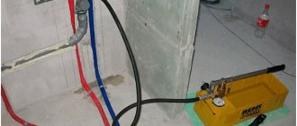
The speed of water movement in the pipes of the heating system.
During the lectures we were told that the optimal speed of water movement in the pipeline is 0.8-1.5 m/s. On some sites I see something similar (specifically about the maximum of one and a half meters per second).
BUT the manual says to take losses per linear meter and speed - according to the appendix in the manual. The speeds there are completely different, the maximum that is on the sign is just 0.8 m/s.
And in the textbook I came across an example of a calculation where the speeds do not exceed 0.3-0.4 m/s.
So what's the point? How to take it in general (and how in reality, in practice)?
I am attaching a screenshot of the sign from the manual.
Thank you all in advance for your answers!
What do you want? Should you find out “military secrets” (how to actually do it), or pass the coursework? If only a course student - then according to the manual, which the teacher wrote and does not know anything else and does not want to know. And if you do it right
, won’t accept it yet.
0.036*G^0.53 - for heating risers
0.034*G^0.49 - for mm mains of the branch, until the load is reduced to 1/3
0.022*G^0.49 - for the end sections of a branch with a load of 1/3 of the entire branch
In the coursework, I calculated it according to the manual. But I wanted to know how things were going.
That is, it turns out in the textbook (Staroverov, M. Stroyizdat) is also not correct (speeds from 0.08 to 0.3-0.4). But perhaps there is only an example of calculation.
Offtop: That is, you also confirm that, in essence, the old (relatively) SNiPs are in no way inferior to the new ones, and in some cases even better. (many teachers tell us about this. In general, the dean of the PSP says that their new SNiP largely contradicts both the laws and himself).
But in principle everything was explained.
and the calculation to reduce diameters along the flow seems to save materials. but increases labor costs for installation. If the labor is cheap, it might make sense. if labor is expensive, there is no point. And if over a long length (heating main) changing the diameter is beneficial, fussing with these diameters within the house does not make sense.
and there is also the concept of hydraulic stability of the heating system - and here the ShaggyDoc schemes win
We disconnect each riser (upper wiring) from the main line with a valve. I've seen that double adjustment taps are installed immediately after the valve. Is it advisable?
And how to disconnect the radiators themselves from the connections: with valves, or install a double adjustment tap, or both? (that is, if this valve could completely shut off the pipeline, then the valve would not be needed at all?)
And for what purpose are pipeline sections isolated? (designation - spiral)
The heating system is two-pipe.
I need to know specifically about the supply pipeline, the question is above.
We have a coefficient of local resistance to the flow input with a turn. Specifically, we use it at the entrance through the louvered grille to the vertical channel. And this coefficient is 2.5 - which is quite a lot.
That is, how to come up with something to get rid of this. One of the exits is if the grille is “in the ceiling”, and then there will be no turning entrance (although there will still be a small one, since the air will be drawn along the ceiling, moving horizontally, and move towards this grille, turn in a vertical direction, but along logically it should be less than 2.5).
You can't put bars in the ceiling in an apartment building, neighbors. and in a single-apartment building, the ceiling will not be beautiful with bars, and debris can get in. that is, the problem cannot be solved this way.
I often drill, then plug
Take the thermal power and the initial from the final temperature. Based on these data, you can absolutely reliably calculate
speed. It will most likely be a maximum of 0.2 m\S. Higher speeds require a pump.
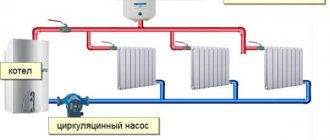
Areas of use of circulation pumps
The main task of the circulation pump is to improve the circulation of coolant through the elements of the heating system. The problem of already cooled water entering heating radiators is well known to residents of the upper floors of apartment buildings. Such situations are associated with the fact that the coolant in such systems moves very slowly and has time to cool before it reaches parts of the heating circuit located at a considerable distance.
When operating autonomous heating systems in country houses, in which water circulates naturally, you may also encounter a problem when radiators installed at the farthest points of the circuit barely heat up. This is also a consequence of insufficient coolant pressure and its slow movement through the pipeline. The installation of circulation pumping equipment allows you to avoid such situations both in apartment buildings and in private houses. By forcibly creating the required pressure in the pipeline, such pumps provide high speed movement of heated water even to the most distant elements of the heating system.
The pump increases the efficiency of existing heating and allows you to improve the system by adding additional radiators or automation elements
Heating systems with natural circulation of liquid that transfers thermal energy are effective when they are used to heat small houses. However, if you equip such systems with a circulation pump, you can not only increase the efficiency of their use, but also save on heating by reducing the amount of energy consumed by the boiler.
In terms of its design, the circulation pump is a motor whose shaft transmits rotation to the rotor. A wheel with blades is installed on the rotor - an impeller. Rotating inside the working chamber of the pump, the impeller pushes the heated liquid entering it into the discharge line, forming a coolant flow with the required pressure. Modern models of circulation pumps can operate in several modes, creating different pressures of the coolant moving through them in heating systems. This option allows you to quickly warm up the house when cold weather sets in by running the pump at maximum power, and then, when a comfortable air temperature has formed throughout the building, switch the device to an economical operating mode.
Circulation pump device for heating
All circulation pumps used to equip heating systems are divided into two large categories: devices with a “wet” and “dry” rotor. In pumps of the first type, all rotor elements are constantly in the coolant environment, and in devices with a “dry” rotor, only a part of such elements are in contact with the pumped medium. Pumps with a “dry” rotor are distinguished by greater power and higher efficiency, but they make a lot of noise during operation, which cannot be said about devices with a “wet” rotor, which produce a minimal amount of noise.
Calculation of coolant movement speed in pipelines
When designing heating systems, special attention should be paid to the speed of movement of the coolant in the pipelines, since the speed directly affects the noise level. According to SP 60.13330.2012
Set of rules. Heating, ventilation and air conditioning. Updated version of SNiP 41-01-2003 maximum water speed in the heating system is determined from the table
According to SP 60.13330.2012. Set of rules. Heating, ventilation and air conditioning. Updated version of SNiP 41-01-2003, the maximum water speed in the heating system is determined from the table.
| Permissible equivalent noise level, dBA | Permissible speed of water movement, m/s, in pipelines with local resistance coefficients of the heating device unit or riser with fittings reduced to the speed of the coolant in the pipes | ||||
| Up to 5 | 10 | 15 | 20 | 30 | |
| 25 | 1.5/1.5 | 1.1/0.7 | 0.9/0.55 | 0.75/0.5 | 0.6/0.4 |
| 30 | 1.5/1.5 | 1.5/1.2 | 1.2/1.0 | 1.0/0.8 | 0.85/0.65 |
| 35 | 1.5/1.5 | 1.5/1.5 | 1.5/1.1 | 1.2/0.95 | 1.0/0.8 |
| 40 | 1.5/1.5 | 1.5/1.5 | 1.5/1.5 | 1.5/1.5 | 1.3/1.2 |
Notes
|
calceng.ru
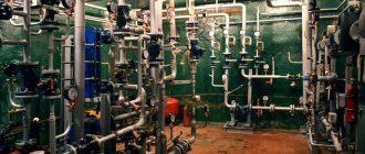
Goals and objectives of hydraulic calculations
From an engineering point of view, a liquid heating system seems to be a rather complex complex, including devices for generating heat, transporting it and releasing it in heated rooms. The ideal operating mode of a hydraulic heating system is considered to be one in which the coolant absorbs maximum heat from the source and transfers it to the room atmosphere without loss during movement. Of course, such a task seems completely unattainable, but a more thoughtful approach allows us to predict the behavior of the system under various conditions and get as close as possible to the benchmark indicators. This is the main goal of designing heating systems, the most important part of which is rightfully considered hydraulic calculation.
The practical goals of hydraulic calculation are:
- Understand at what speed and in what volume the coolant moves in each node of the system.
- Determine what impact a change in the operating mode of each device has on the entire complex as a whole.
- Determine what performance and performance characteristics of individual components and devices will be sufficient for the heating system to perform its functions without significantly increasing the cost and providing an unreasonably high margin of reliability.
- Ultimately, to ensure a strictly dosed distribution of thermal energy across various heating zones and to ensure that this distribution will be maintained with high constancy.
One can say more: without at least basic calculations it is impossible to achieve acceptable operating stability and long-term use of equipment. Modeling the operation of a hydraulic system, in fact, is the basis on which all further design development is built.
What could be the consequences of narrowing the diameter of the heating pipe?
Narrowing the pipe diameter is extremely undesirable. When wiring around the house, it is recommended to use the same standard size - there is no need to increase or decrease it. The only possible exception would be a large length of the circulation circuit. But even in this case you need to be careful.
But in this same situation, it turns out that the residents who made such a replacement of pipes automatically “stole” approximately 40% of the heat and water passing through the pipes from their neighbors in this riser. Therefore, it is worth understanding that the thickness of pipes that are arbitrarily replaced in a heating system is not a matter of private decision; this cannot be done. If steel pipes are replaced with plastic ones, no matter how you look at it, you will have to widen the holes in the ceilings.
There is such an option in this situation. When replacing risers, you can pass new pieces of steel pipes of the same diameter into the old holes; their length will be 50-60 cm (this depends on such a parameter as the thickness of the ceiling). And then they are connected with couplings to plastic pipes. This option is quite acceptable.
Data on how to calculate the diameter of a heating pipe
To calculate the diameter of the pipeline, you will need the following data: this is the total heat loss of the home, the length of the pipeline, and the calculation of the power of the radiators in each room, as well as the wiring method. The outlet can be one-pipe, two-pipe, have forced or natural ventilation.
Unfortunately, it is impossible to accurately calculate the pipe cross-section. One way or another, you will have to choose from a couple of options. This point is worth clarifying: a certain amount of heat needs to be delivered to the radiators, while achieving uniform heating of the batteries. If we are talking about systems with forced ventilation, then this is done using pipes, a pump and the coolant itself. All that is needed is to drive the required amount of coolant over a certain period of time.
It turns out that you can choose pipes of a smaller diameter and supply the coolant at a higher speed. You can also make a choice in favor of pipes of a larger cross-section, but reduce the intensity of the coolant supply. The first option is preferable.
Overview of hydraulic calculation programs
Essentially, any hydraulic calculation of water heating systems is considered a difficult engineering task. To solve this problem, a number of software packages have been developed that facilitate the implementation of such a procedure.
You can try to perform a hydraulic calculation of the heating system in Excel using ready-made formulas. However, the following problems may occur:
- Large error. In many cases, as an example of a hydraulic calculation of a heating system, diagrams with one or two pipes are taken. Finding the same calculations for the collector is problematic;
- To correctly account for resistance in terms of pipeline hydraulics, reference data is needed that is not included in the form. They must be searched for and entered additionally.
Taking such factors into account, experts recommend using calculation programs. A large number of them are paid, but some have a demo version with few features.
Oventrop CO
The most simple and clear program for hydraulic calculation of heating networks. An intuitive interface and flexible settings can help you quickly understand the invisible aspects of data entry. Small problems may appear when setting up the complex for the first time. You will need to enter all the parameters of the system, starting from the pipe material itself and ending with the placement of the TENS.
The influence of temperature on the properties of the coolant
In addition to the factors described above, the temperature of the water in the heating pipes affects its properties. This is the basis of the operating principle of gravity heating systems. As the heating level of water increases, it expands and circulation occurs.
Coolants for heating systems
However, if antifreeze is used, exceeding the normal temperature in the radiators can lead to different results. Therefore, for heating with a coolant other than water, you should first find out the permissible heating rates. This does not apply to the temperature of central heating radiators in the apartment, since such systems do not use antifreeze-based liquids.
Antifreeze is used if there is a possibility that low temperatures will affect radiators. Unlike water, it does not begin to change from a liquid to a crystalline state when it reaches 0°C. However, if the heat supply operation exceeds the norms of the temperature table for heating to a greater extent, the following phenomena may occur:
- Foaming. This entails an increase in the volume of coolant and, as a result, an increase in pressure. The reverse process will not be observed when the antifreeze cools;
- Formation of limescale. Antifreeze contains a certain amount of mineral components. If the heating temperature in the apartment is violated, they begin to precipitate. Over time, this will lead to clogged pipes and radiators;
- Increasing the density index. Malfunctions of the circulation pump may occur if its rated power was not designed for such situations.
Therefore, it is much easier to monitor the water temperature in the heating system of a private home than to control the degree of heating of antifreeze. In addition, when evaporating, ethylene glycol-based compounds emit gas that is harmful to humans. Currently, they are practically not used as a coolant in autonomous heat supply systems.
Before pouring antifreeze into the heating, you should replace all rubber gaskets with paranitic gaskets. This is due to the increased permeability of this type of coolant.
Dynamic parameters of the coolant
We move on to the next stage of calculations - analysis of coolant consumption. In most cases, the heating system of an apartment differs from other systems - this is due to the number of heating panels and the length of the pipeline. Pressure is used as an additional “driving force” for flow vertically through the system.
In private one- and multi-story buildings, old panel apartment buildings, high-pressure heating systems are used, which makes it possible to transport the heat-releasing substance to all sections of the branched, multi-ring heating system and raise water to the entire height (up to the 14th floor) of the building.
On the contrary, an ordinary 2- or 3-room apartment with autonomous heating does not have such a variety of rings and branches of the system; it includes no more than three circuits.
This means that the coolant is transported using the natural process of water flow. But you can also use circulation pumps; heating is provided by a gas/electric boiler.
We recommend using a circulation pump for heating rooms larger than 100 m2. The pump can be installed either before or after the boiler, but usually it is installed on the “return” - lower fluid temperature, less airiness, longer pump life
Specialists in the field of design and installation of heating systems define two main approaches in terms of calculating the volume of coolant:
- According to the actual capacity of the system. Without exception, all volumes of cavities where the flow of hot water will flow are summed up: the sum of individual sections of pipes, sections of radiators, etc. But this is a rather labor-intensive option.
- According to boiler power. Here the opinions of experts differ greatly, some say 10, others 15 liters per unit of boiler power.
From a pragmatic point of view, you need to take into account the fact that probably the heating system will not only supply hot water for the room, but also heat water for the bath/shower, washbasin, sink and dryer, and maybe for a hydromassage or jacuzzi. This option is simpler.
Therefore, in this case, we recommend setting 13.5 liters per unit of power. Multiplying this number by the boiler power (8.08 kW) we obtain the estimated volume of water mass - 109.08 liters.
The calculated coolant velocity in the system is precisely the parameter that allows you to select a certain pipe diameter for the heating system.
It is calculated using the following formula:
V = (0.86*W*k)/t-to,
Where:
- W – boiler power;
- t – temperature of the supplied water;
- to – water temperature in the return circuit;
- k – boiler efficiency (0.95 for a gas boiler).
Substituting the calculated data into the formula, we have: (0.86 * 8080 * 0.95)/80-60 = 6601.36/20 = 330 kg/h. Thus, in one hour, 330 liters of coolant (water) move through the system, and the system capacity is about 110 liters.
Coolant flow in the heating system
The flow rate in the coolant system implies the mass amount of coolant (kg/s) intended to supply the required amount of heat to the heated room. The calculation of the coolant in the heating system is determined as the quotient of dividing the calculated heat demand (W) of the room (rooms) by the heat transfer of 1 kg of heating fluid (J/kg).
Some tips for filling the heating system with coolant in the video:
The coolant flow in the system during the heating season in vertical central heating systems changes, since they are regulated (this is especially true for the gravitational circulation of the coolant - in more detail: “Calculation of the gravitational heating system of a private house - diagram”). In practice, in calculations, coolant flow is usually measured in kg/h.
Everyone should know the standards: coolant parameters for the heating system of an apartment building
During the cold season, residents of apartment buildings often trust already installed central heating batteries to maintain the temperature in their rooms.
This is the advantage of urban high-rise buildings over the private sector - from mid-October to the end of April, public utilities take care of the constant heating of residential premises. But their work is not always flawless.
Many have encountered pipes that are not hot enough in winter frosts, and a real heat attack in the spring. In fact, the optimal temperature of the apartment at different times of the year is determined centrally, and must correspond to the accepted GOST.
Purposes of hydraulic calculation
The objectives of hydraulic calculation are as follows:
- Select the optimal pipeline diameters.
- Link pressures in individual branches of the network.
- Select a circulation pump for the heating system.
Let's look at each of these points in more detail.
1.
Selection of pipeline diameters
If the system is branched - there is a short and a long branch, then on the long branch there is a large flow rate, and on the short branch - less. In this case, the short branch should be made from pipes of smaller diameters, and the long branch should be made from pipes of larger diameter.
And, as the flow rate decreases, from the beginning to the end of the branch, the diameters of the pipes should decrease so that the coolant speed is approximately the same.
2.
Linking pressures in individual branches of the network
Linking can be done by selecting the appropriate pipe diameters or, if the possibilities of this method have been exhausted, then by installing pressure flow regulators or control valves on individual branches.
Adjustment fittings may be different.
Budget option - install a control valve - i.e. valve with smooth adjustment, which has a gradation in setting. Each valve has its own characteristics. During hydraulic calculations, the designer looks at what pressure needs to be extinguished, and the so-called pressure discrepancy between the long and short branches is determined. Then, based on the characteristics of the valve, the designer determines how many revolutions this valve will need to open from the fully closed position. For example, by 1, 1.5 or 2 turns. Depending on the degree of opening of the valve, different resistance will be added.
A more expensive and complex version of control valves is the so-called. pressure regulators and flow regulators. These are devices on which we set the required flow rate or the required pressure drop, i.e. pressure drop on this branch. In this case, the devices themselves control the operation of the system and, if the flow does not meet the required level, they open the cross-section and the flow increases. If the flow rate is too high, the cross section is blocked. The same thing happens with pressure.
If all consumers, after an overnight decrease in heat transfer, simultaneously opened their heating appliances in the morning, then the coolant will try, first of all, to flow to the appliances closest to the heating point, and will reach the furthest ones after hours. Then the pressure regulator will work, covering the nearest branches and thereby ensuring a uniform supply of coolant to all branches.
3.
Selection of a circulation pump by pressure (pressure) and flow (supply)
If there are several circulation pumps in the system, then if they are installed in series, their pressure will be summed up, and the flow rate will be total. If the pumps operate in parallel, then their flow rate is summed up, and the pressure will be the same.
Important: Having determined the pressure loss in the system during the hydraulic calculation, you can select a circulation pump that will optimally match the parameters of the system, ensuring optimal costs - capital (cost of the pump) and operating (cost of electricity for circulation)
Preparation for calculation and its stages
Hydraulic heating calculation allows you to find out what operational parameters the heating system should have with given initial data in order to demonstrate better efficiency. At this stage of the project, it is necessary to obtain the following characteristics:
- Pipe diameter (it determines the throughput of the system).
- Head and pressure losses. The total losses (across the entire northwestern district) and separately for each section are calculated.
- The optimal volume of water in the circuit, the speed of its movement, the capacity of the expansion tank.
- Calculation of system resistance, selection of circulation pump.
Table for determining the diameter of pipes Source oboiman.ru
Before calculating the hydraulic parameters, it is necessary to perform a thermal calculation. It will give you an idea of how much heating energy is needed for each room. This, in turn, will allow you to choose the type of heating system, heat generator and heating devices.
Based on these data, pipes and fittings, a methodology are selected, and the pipeline is calculated based on flow and pressure. At the last stage, an axonometric wiring diagram is drawn up (a visual projection of communication networks made in a three-coordinate system).
Optimal values in an individual heating system
Autonomous heating helps to avoid many problems that arise with a centralized network, and the optimal temperature of the coolant can be adjusted according to the season.
In the case of individual heating, the concept of standards includes the heat transfer of a heating device per unit area of the room where this device is located. The thermal regime in this situation is ensured by the design features of the heating devices. It is important to ensure that the coolant in the network does not cool below 70 °C. 80 °C is considered optimal
With a gas boiler, it is easier to control heating, because manufacturers limit the ability to heat the coolant to 90 °C. Using sensors to regulate the gas supply, the heating of the coolant can be adjusted.
It is a little more difficult with solid fuel devices; they do not regulate the heating of the liquid, and can easily turn it into steam. And it is impossible to reduce the heat from coal or wood by turning the knob in such a situation. Control of heating of the coolant is quite conditional with high errors and is carried out by rotary thermostats and mechanical dampers.
Electric boilers allow you to smoothly regulate the heating of the coolant from 30 to 90 °C. They are equipped with an excellent overheat protection system.
Coordination of water temperature in the boiler and system
There are two options for how you can coordinate high-temperature coolants in the boiler and lower-temperature coolants in the heating system:
- In the first case, the efficiency of the boiler’s operation should be neglected and, at its outlet, the coolant should be supplied to the degree of heating that the system currently requires. This is what they do in small boiler houses. But in the end, it turns out that the coolant is not always supplied in accordance with the optimal temperature conditions according to the schedule (read: “Schedule of the heating season - beginning and end of the season”). Recently, more and more often in small boiler houses, a water heating regulator is installed at the outlet, taking into account the readings, which records the coolant temperature sensor.
- In the second case, the heating of water for transportation through networks at the exit from the boiler room is maximized. Then, in the immediate vicinity of consumers, the temperature of the coolant is automatically adjusted to the required values. This method is considered more progressive; it is used in many large heating networks, and since regulators and sensors have become cheaper, it is increasingly used in small heating supply facilities.
Heat generator power
One of the main components of the heating system is the boiler: electric, gas, combined – it doesn’t matter at this stage. Because its main characteristic is important to us - power, that is, the amount of energy per unit of time that will be spent on heating.
The power of the boiler itself is determined by the formula below:
Wboiler = (Sroom*Wshare) / 10,
Where:
- Sroom – the sum of the areas of all rooms that require heating;
- Wdel – specific power taking into account the climatic conditions of the location (this is why it was necessary to know the climate of the region).
Typically, for different climatic zones we have the following data:
- northern regions – 1.5 – 2 kW/m2;
- central zone – 1 – 1.5 kW/m2;
- southern regions – 0.6 – 1 kW/m2.
These figures are quite arbitrary, but nevertheless provide a clear numerical answer regarding the influence of the environment on the apartment heating system.
This map shows climate zones with different temperature regimes. The location of the housing relative to the zone determines how much energy needs to be spent on heating a square meter of kWatt of energy (+)
The amount of the apartment area that needs to be heated is equal to the total area of the apartment and is equal, that is, 65.54-1.80-6.03 = 57.71 m2 (minus the balcony). The specific boiler power for the central region with cold winters is 1.4 kW/m2. Thus, in our example, the calculated power of the heating boiler is equivalent to 8.08 kW.
Temperature standards
- DBN (V. 2.5-39 Heat networks);
- SNiP 2.04.05 “Heating, ventilation and air conditioning.”
For the calculated supply water temperature, the figure is taken that is equal to the water temperature at the outlet of the boiler, according to its passport data.
For individual heating, deciding what the coolant temperature should be should take into account the following factors:
- 1 Beginning and ending of the heating season based on the average daily outdoor temperature of +8 °C for 3 days;
- 2 The average temperature inside heated premises of housing, communal and public importance should be 20 °C, and for industrial buildings 16 °C;
- 3 The average design temperature must comply with the requirements of DBN V.2.2-10, DBN V.2.2.-4, DSanPiN 5.5.2.008, SP No. 3231-85.
According to SNiP 2.04.05 “Heating, ventilation and air conditioning” (clause 3.20), the coolant limit values are as follows:
- 1 For a hospital – 85 °C (excluding psychiatric and drug departments, as well as administrative or household premises);
- 2 For residential, public, and domestic buildings (not counting halls for sports, trade, spectators and passengers) – 90 °C;
- 3 For auditoriums, restaurants and premises for production of categories A and B – 105 °C;
- 4 For catering establishments (excluding restaurants) – this is 115 °C;
- 5 For production premises (categories B, D and D), where flammable dust and aerosols are emitted – 130 °C;
- 6 For staircases, lobbies, pedestrian crossings, technical premises, residential buildings, production premises without the presence of flammable dust and aerosols – 150 °C.
Depending on external factors, the water temperature in the heating system can be from 30 to 90 °C. When heated above 90 °C, dust and paintwork begin to decompose. For these reasons, sanitary standards prohibit greater heating.
To calculate optimal indicators, special graphs and tables can be used, which define standards depending on the season:
- With an average reading outside the window of 0 °C, the supply for radiators with different wiring is set at 40 to 45 °C, and the return temperature at 35 to 38 °C;
- At -20 °C, the supply is heated from 67 to 77 °C, and the return rate should be from 53 to 55 °C;
- At -40 °C outside the window, all heating devices are set to the maximum permissible values. On the supply side it is from 95 to 105 °C, and on the return side it is 70 °C.
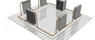
Heating system wiring diagram and heating pipe diameter
The heating wiring diagram is always taken into account. It can be two-pipe vertical, two-pipe horizontal and single-pipe. A two-pipe system involves both upper and lower placement of lines. But the single-pipe system takes into account the economical use of the length of the lines, and is suitable for heating with natural circulation. Then the two-pipe system will require the mandatory inclusion of a pump in the circuit.
There are three types of horizontal wiring:
- Dead end;
- Beam or collector;
- With parallel movement of water.
By the way, in the diagram of a single-pipe system there may also be a so-called bypass pipe. It will become an additional line for fluid circulation if one or more radiators are turned off. Usually, shut-off valves are installed on every radiator, which allow you to shut off the water supply if necessary.
Selecting the main outline
Hydraulic arrow separates boiler and heating circuits
Here it is necessary to consider separately two schemes - one-pipe and two-pipe. In the first case, the calculation must be carried out through the most loaded riser, where a large number of heating devices and shut-off valves are installed.
In the second case, the busiest circuit is selected. It is on this basis that the calculation must be made. All other circuits will have much lower hydraulic resistance.
In the event that horizontal pipe decoupling is considered, the busiest ring of the lower floor is selected. Load refers to thermal load.
Coolant speed
Schematic calculation
There is a minimum speed of hot water inside the heating system at which the heating itself operates optimally. This is 0.2-0.25 m/s. If it decreases, then air begins to be released from the water, which leads to the formation of air jams. Consequences - the heating will not work and the boiler will boil.
This is the lower threshold, and as for the upper level, it should not exceed 1.5 m/s. Exceeding it threatens the appearance of noise inside the pipeline. The most acceptable indicator is 0.3-0.7 m/s.
If you need to accurately calculate the speed of water movement, you will have to take into account the parameters of the material from which the pipes are made. Especially in this case, the roughness of the internal surfaces of the pipes is taken into account.
For example, hot water moves through steel pipes at a speed of 0.25-0.5 m/s, through copper pipes 0.25-0.7 m/s, through plastic pipes 0.3-0.7 m/s.
Hydraulic calculation of the heating system taking into account pipelines.
Hydraulic calculation of the heating system taking into account pipelines.
When carrying out further calculations, we will use all the main hydraulic parameters, including coolant flow, hydraulic resistance of fittings and pipelines, coolant speed, etc. There is a complete relationship between these parameters, which is what you need to rely on when making calculations.
For example, if you increase the speed of the coolant, the hydraulic resistance of the pipeline will simultaneously increase. If you increase the flow rate of the coolant, taking into account a pipeline of a given diameter, the speed of the coolant will simultaneously increase, as well as the hydraulic resistance. And the larger the diameter of the pipeline, the lower the coolant velocity and hydraulic resistance will be. Based on the analysis of these relationships, it is possible to turn the hydraulic calculation of the heating system (the calculation program is available on the Internet) into an analysis of the parameters of the efficiency and reliability of the entire system, which, in turn, will help reduce the cost of materials used.
The heating system includes four basic components: heat generator, heating devices, pipeline, shut-off and control valves. These elements have individual hydraulic resistance parameters that must be taken into account when making calculations. Let us remember that hydraulic characteristics are not constant. Leading manufacturers of materials and heating equipment are required to provide information on specific pressure losses (hydraulic characteristics) for the equipment or materials they produce.
For example, the calculation for polypropylene pipelines from the FIRAT company is greatly facilitated by the given nomogram, which indicates the specific pressure loss or pressure in the pipeline for 1 linear meter of pipe. Analysis of the nomogram allows us to clearly trace the above-mentioned relationships between individual characteristics. This is the main essence of hydraulic calculations.
Hydraulic calculation of water heating systems: coolant flow
We think you have already drawn an analogy between the term “coolant flow” and the term “coolant quantity”. So, the coolant consumption will directly depend on what thermal load falls on the coolant as it moves heat to the heating device from the heat generator.
Hydraulic calculation involves determining the level of coolant flow regarding a given area. The design section is a section with a stable coolant flow rate and a constant diameter.
Hydraulic calculation of heating systems: example
If a branch includes ten kilowatt radiators, and the coolant flow rate is calculated to transfer heat energy at a level of 10 kilowatts, then the calculated section will be a section from the heat generator to the radiator, which is the first in the branch. But only on the condition that this area is characterized by a constant diameter. The second section is located between the first radiator and the second radiator. Moreover, if in the first case the transfer rate of 10 kilowatt thermal energy was calculated, then in the second section the calculated amount of energy will already be 9 kilowatts, with a gradual decrease as the calculations are carried out. The hydraulic resistance must be calculated simultaneously for the supply and return pipelines.
Hydraulic calculation of a single-pipe heating system involves calculating coolant flow
for the calculated area using the following formula:
Qch – thermal load of the design area in watts. For example, for our example, the heat load on the first section will be 10,000 watts or 10 kilowatts.
c (specific heat capacity for water) – constant, equal to 4.2 kJ/(kg•°C)
tg – temperature of the hot coolant in the heating system.
to is the temperature of the cold coolant in the heating system.
Hydraulic calculation of the heating system: coolant flow rate
The minimum coolant speed should take a threshold value of 0.2 - 0.25 m/s. If the speed is lower, excess air will be released from the coolant. This will lead to the appearance of air pockets in the system, which, in turn, can cause partial or complete failure of the heating system. As for the upper threshold, the coolant speed should reach 0.6 - 1.5 m/s. If the speed does not rise above this indicator, then hydraulic noise will not form in the pipeline. Practice shows that the optimal speed range for heating systems is 0.3 - 0.7 m/s.
If there is a need to calculate the coolant velocity range more accurately, then you will have to take into account the parameters of the material of the pipelines in the heating system. More precisely, you will need a roughness coefficient for the internal piping surface. For example, if we are talking about steel pipelines, then the optimal coolant speed is considered to be 0.25 - 0.5 m/s. If the pipeline is polymer or copper, then the speed can be increased to 0.25 - 0.7 m/s. If you want to play it safe, carefully read what speed is recommended by equipment manufacturers for heating systems. A more accurate range of recommended coolant speed depends on the material of the pipelines used in the heating system, or more precisely on the roughness coefficient of the inner surface of the pipelines. For example, for steel pipelines it is better to adhere to a coolant speed of 0.25 to 0.5 m/s; for copper and polymer (polypropylene, polyethylene, metal-plastic pipelines) from 0.25 to 0.7 m/s, or use the manufacturer’s recommendations, if available.
Calculation of hydraulic resistance of the heating system: pressure loss
The pressure loss in a certain section of the system, which is also called the term “hydraulic resistance,” is the sum of all losses due to hydraulic friction and local resistance. This indicator, measured in Pa, is calculated using the formula:
ΔPuch=R* l + ( (ρ * ν2) / 2) * Σζ
ν is the speed of the coolant used, measured in m/s.
ρ is the density of the coolant, measured in kg/m3.
R – pressure loss in the pipeline, measured in Pa/m.
l is the estimated length of the pipeline on the section, measured in m.
Σζ is the sum of the local resistance coefficients in the area of equipment and shut-off and control valves.
As for the total hydraulic resistance, it is the sum of all hydraulic resistances of the design sections.
Hydraulic calculation of a two-pipe heating system: selection of the main branch of the system
If the system is characterized by a parallel movement of the coolant, then for a two-pipe system the ring of the busiest riser is selected through the lower heating device. For a single-pipe system - a ring through the busiest riser.
Operating principle of heating controllers
The temperature regulator of the coolant circulating in the heating system is a device that provides automatic control and adjustment of water temperature parameters.
This device, shown in the photo, consists of the following elements:
- computing and switching node;
- working mechanism on the hot coolant supply pipe;
- an executive unit designed to mix in the coolant coming from the return. In some cases, a three-way valve is installed;
- booster pump at the supply section;
- The booster pump is not always in the “cold bypass” section;
- sensor on the coolant supply line;
- valves and shut-off valves;
- return sensor;
- outside air temperature sensor;
- several room temperature sensors.
Now you need to understand how the coolant temperature is regulated and how the regulator functions.
At the outlet of the heating system (return), the temperature of the coolant depends on the volume of water passing through it, since the load is a relatively constant value. By covering the liquid supply, the regulator thereby increases the difference between the supply and return lines to the required value (sensors are installed on these pipelines).
When, on the contrary, it is necessary to increase the coolant flow, then a booster pump is installed into the heating system, which is also controlled by the regulator. In order to lower the temperature of the incoming water flow, a cold bypass is used, which means that part of the coolant that has already circulated through the system is again directed to the inlet.
As a result, the regulator, redistributing coolant flows depending on the data recorded by the sensor, ensures compliance with the temperature schedule of the heating system.
Often such a regulator is combined with a hot water supply regulator using one computing node. The device that regulates DHW is easier to operate and in terms of actuators. Using a sensor on the hot water supply line, the passage of water through the boiler is adjusted and, as a result, it consistently has the standard 50 degrees (read: “Heating through a water heater”).
Pre-balancing the system
The most important final goal of the hydraulic calculation of the heating system is to calculate the throughput values at which a strictly dosed amount of coolant with a certain temperature is supplied to each part of each heating circuit, which ensures normalized heat release on the heating devices. This task seems difficult only at first glance. In reality, balancing is accomplished by control valves that limit the flow. For each valve model, both the Kvs coefficient for the fully open state and a graph of the change in the Kv coefficient for different degrees of opening of the control rod are indicated. By changing the capacity of the valves, which are usually installed at the connection points of heating devices, it is possible to achieve the desired distribution of the coolant, and therefore the amount of heat transferred by it.
Recommendations for selection and operation
When choosing a coolant for a heating system, it is worth knowing that not all heating systems are capable of working with antifreeze. Many manufacturers do not allow the possibility of using it as a coolant; this often serves as a reason for refusing warranty service for the equipment.
Before filling the heating system with coolant, you need to carefully study its features, such as:
- composition, purpose and types of additives;
- freezing point;
- duration of operation without replacement;
- interaction of antifreeze with rubber, plastic, metal, etc.;
- harmlessness to health and environmental safety (replacing the coolant in the system will require draining it).
A surface tension coefficient lower than that of water gives it fluidity and allows it to easily penetrate into pores and microcracks. All connections must be sealed with Teflon, paronite or resistant rubber gaskets. It makes no sense to use zinc-coated elements in the heating system. As a result of a chemical reaction, it will be destroyed during the first heating season.
The calculation shows that due to its low heat capacity, antifreeze accumulates and releases heat energy more slowly, so it is necessary to use pipes with an increased diameter and increase the number of radiator sections. The circulation of coolant in the system is hampered by the increased viscosity of antifreeze, which reduces efficiency. This can be eliminated by replacing the pump with a more powerful one.
A preliminary calculation will help to correctly design the heating circuit and will allow you to find out the required volume of coolant in the system.
It is unacceptable to exceed the temperature of the coolant in the heating system more than that declared by the manufacturer. Even a short-term increased temperature of the coolant worsens its parameters, leads to the disintegration of additives and the appearance of insoluble formations in the form of sediment and acids. When sediment gets on the heating elements, carbon deposits form. Acids, when reacting with metals, contribute to the formation of corrosion.
The service life of antifreeze depends solely on the selected mode and is 3-5 years (up to 10 seasons). Before replacing it, it is necessary to flush the entire system and boiler with water.
Head and pressure losses
Calculation of parameters using the relationships described above would be sufficient for ideal models. In real life, both the volumetric flow and the coolant velocity will always differ from the calculated ones at different points in the system. The reason for this is hydrodynamic resistance to the movement of the coolant. This is due to a number of factors:
- The forces of friction of the coolant against the walls of the pipes.
- Local flow resistance formed by fittings, taps, filters, thermostatic valves and other fittings.
- The presence of branches of connecting and branch types.
- Turbulent turbulence at turns, contractions, expansions, etc.
The task of finding the pressure drop and velocity in different parts of the system is rightfully considered the most difficult; it lies in the field of calculations of hydrodynamic media. Thus, the friction forces of the liquid on the internal surfaces of the pipe are described by a logarithmic function that takes into account the roughness of the material and kinematic viscosity. With the calculations of turbulent vortices, everything is even more complicated: the slightest change in the profile and shape of the channel makes each individual situation unique. To facilitate calculations, two reference coefficients are introduced:
- Kvs - characterizing the throughput of pipes, radiators, separators and other sections close to linear.
- Kms - determining local resistance in various fittings.
These coefficients are indicated by manufacturers of pipes, valves, taps, and filters for each individual product. Using the coefficients is quite easy: to determine the pressure loss, Kms is multiplied by the ratio of the square of the coolant velocity to the double value of the acceleration of gravity:
Δhms = Kms (V2/2g) or Δpms = Kms (ρV2/2)
- Δhms - pressure loss at local resistances, m
- Δpms — pressure loss at local resistances, Pa
- Kms - local resistance coefficient
- g—gravitational acceleration, 9.8 m/s2
- ρ—coolant density, for water 1000 kg/m3
The pressure loss in linear sections is the ratio of the channel capacity to a known capacity coefficient, and the result of the division must be raised to the second power:
Р = (G/Kvs)2
- P—pressure loss, bar
- G—actual coolant flow, m3/hour
- Kvs - throughput, m3/hour