The name of the “two-pipe” system speaks for itself. For operation, two pipes are required: one supplies coolant heated to the required degree, and the second returns it to the boiler to replenish the lost temperature.
This solution allows you to implement both a natural circulation scheme and a forced one, and use boilers using any fuel to heat the coolant. The two-pipe heating system is popular in both individual and large-scale construction.
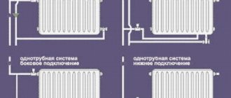
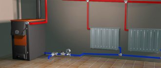
Connecting a radiator to a two-pipe system
Advantages and disadvantages of single-pipe and two-pipe heating systems
The main difference between the two heating schemes is that the two-pipe connection system is more efficient in operation due to the parallel arrangement of two pipes, one of which supplies the heated coolant to the radiator, and the other removes the cooled liquid.
The single-pipe system circuit is a sequential type wiring, due to which the first connected radiator receives the maximum amount of thermal energy, and each subsequent one heats up less and less.
However, efficiency is an important, but not the only criterion that you need to rely on when deciding to choose one scheme or another. Let's consider all the pros and cons of both options.
Single pipe heating system
Advantages:
- ease of design and installation;
- savings in materials due to the installation of only one line;
- natural circulation of coolant, possible due to high pressure.
Flaws:
- complex calculation of thermal and hydraulic parameters of the network;
- the difficulty of eliminating errors made during design;
- all network elements are interdependent; if one section of the network malfunctions, the entire circuit stops working;
- the number of radiators on one riser is limited;
- it is impossible to regulate the flow of coolant into a separate battery;
- high heat loss coefficient.
Two-pipe heating system
Advantages:
- possibility of installing a thermostat on each radiator;
- independence of operation of network elements;
- the ability to insert additional batteries into an already assembled line;
- ease of eliminating errors made at the design stage;
- to increase the volume of coolant in heating devices, there is no need to add additional sections;
- no restrictions on the length of the contour;
- coolant with the required temperature is supplied throughout the entire pipeline ring, regardless of the heating parameters.
Flaws:
- complex connection diagram compared to a single-pipe;
- higher consumption of materials;
- installation requires a lot of time and labor.
Thus, a two-pipe heating system is preferable in all respects. Why do the owners of apartments and houses refuse it in favor of a single-pipe scheme? Most likely, this is due to the high cost of installation and the high consumption of materials required to lay two highways at once. However, one should take into account the fact that a two-pipe system involves the use of pipes of a smaller diameter, which are cheaper, so the total cost of installing a two-pipe option will not be much more than a single-pipe one.
Owners of apartments in new buildings are lucky: in new buildings, unlike residential buildings of Soviet construction, a more efficient two-pipe heating system is increasingly used.
Options for using a single-pipe radiator connection diagram: photo
The following options exist.
The wiring diagram is one of the main schemes, which is selected taking into account the number of floors, the number of radiators, and the planned amount.
Vertical with lots of batteries
risers with a smaller diameter depart from it , and heating appliances in the apartment and pipes are connected to them. The scheme is as simple as possible and the work done on it is cheap.
The wiring can be bottom or top . If it is from the top, the supply is laid in the attic or technical floor. The risers are connected in series, through which the coolant enters the apartments.
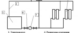
Photo 2. Diagram of a vertical single-circuit heating system: 1 - boiler, 2 - circulation pump, 3 - expander, 4 - air collector.
This scheme is not particularly flexible, plus you should immediately count on a large number of radiators. If the project is designed to use the gravitational movement of water, this scheme will work well.
Types of two-pipe systems
Two-pipe systems are divided into types depending on:
- circuit type (open and closed);
- method and direction of water flow (flowing and dead-end);
- method of moving coolant (with natural and forced circulation).
Open and closed loop systems
The open-type two-pipe system has not taken root in city apartments due to the peculiarity associated with the upper pipe distribution, which requires the use of an expansion tank. This device makes it possible to control and replenish the heating system with water, but there is not always space in the apartment to install such a large device.
Flow-through and dead-end
In a flow-through system, the direction of water flow in the supply and discharge pipes does not change. With a dead-end circuit, the coolant in the supply and return pipes moves in opposite directions. In such a network, bypasses are installed, and the radiators are located in closed areas, which makes it possible to turn off any of them without disturbing the operation of the heating.
With natural and forced circulation
For natural circulation of water, pipes are laid with a mandatory slope, and an expansion tank is installed at the highest point of the system. Forced circulation is carried out by a pump installed in the return pipe. Such a system requires air vent valves or Mayevsky taps.
Selection of pipes by diameter
The choice of pipe cross-section must be made based on the volume of coolant that must pass per unit of time. It, in turn, depends on the thermal power required to heat the room.
In our calculations, we will assume that the amount of heat loss is known and there is a numerical value of the heat required for heating.
Calculations begin with the final, that is, the farthest radiator of the system. To calculate the coolant flow for a room, you will need the formula:
G=3600×Q/(c×Δt) , where:
- G – water consumption for heating the room (kg/h);
- Q is the thermal power required for heating (kW);
- c – heat capacity of water (4.187 kJ/kg×°C);
- Δt is the temperature difference between the hot and cooled coolant, taken equal to 20 °C.
For example, it is known that the thermal power for heating a room is 3 kW. Then the water consumption will be: 3600×3/(4.187×20)=129 kg/h, that is, about 0.127 cubic meters. m of water per hour.
In order for water heating to be balanced as accurately as possible, it is necessary to determine the cross-section of the pipes. To do this we use the formula:
S=GV/(3600×v) , where:
- S is the cross-sectional area of the pipe (m2);
- GV – volumetric water flow (m3/h);
- v is the speed of water movement, is in the range of 0.3−0.7 m/s.
If the system uses natural circulation, then the movement speed will be minimal - 0.3 m/s. But in the example under consideration, let’s take the average value - 0.5 m/s. Using the indicated formula, we calculate the cross-sectional area, and based on it, the internal diameter of the pipe. It will be 0.1 m. We select a polypropylene pipe of the nearest larger diameter. This product has an internal diameter of 15 mm.
Then we move on to the next room, calculate the coolant flow for it, sum it up with the flow rate for the calculated room and determine the diameter of the pipe. And so on all the way to the boiler.
Components of a two-pipe individual heating system
A two-pipe diagram of an apartment’s individual heating network includes the following elements:
- heating boiler;
- thermostatic valves for radiators;
- automatic air vent valve;
- balancing device;
- pipes and fittings;
- radiators;
- valves and taps;
- expansion tank;
- filter;
- temperature manometer;
- circulation pump (if necessary);
- safety valves.
Installation of a two-pipe heating system with upper and lower wiring
The two-pipe system has variations according to the installation scheme. The most commonly used are top and bottom wiring types.
Upper wiring
Laying the top wiring involves installation work to secure the heating system under the ceiling of the room. Batteries installed in places where cold air accumulates (window openings, balcony doors) are supplied with branches coming from the main pipeline. Liquid enters the lower part of the pipeline, which is a drain, and has time to cool during circulation. This system is suitable for large premises; in one-room or two-room apartments, installing heating with overhead wiring is not recommended, since this is unprofitable for the owner from an economic and design point of view.
Installation of a heating circuit with upper horizontal wiring is carried out according to the following scheme:
- The corner fitting required to connect the upward pipe is mounted to the boiler outlet.
- Using tees and corners, horizontal installation of the top line is carried out: the tees are installed above the battery, the corners are installed on the sides.
- The final stage of installation of the upper horizontal is the installation of tees with branch pipes on the battery, supplemented with a shut-off valve.
- On the lower branch, the outlet ends are connected to the common return line, in the section of which a pressure pumping station (circulation pump) is installed.
Bottom wiring
In a network with bottom wiring, outlet channels and supply heat-conducting pipes are installed. The superiority of the lower mounting scheme is expressed in the following:
- The heating pipes are located in the lower, inconspicuous part of the room, which provides more opportunities for the implementation of various design projects.
- Minimum pipe consumption: all installation work is carried out almost at the same level. The wiring point and radiator pipes are located at a short distance from each other.
- Due to the simplicity of the circuit, installation of such a system will be possible even for a non-professional.
Important! The lower wiring is installed only if the circulation of the coolant will be forced, otherwise the water will not move through the heating pipes. This scheme is applicable exclusively in city apartments or one-story buildings.
One of the disadvantages of the scheme is the complexity of adjustment and balancing, but the ease of installation and reliability in operation covers these disadvantages.
- Installation work begins with the outlet from the boiler pipes using an angle fitting in a downward direction.
- The wiring is carried out at floor level along the wall using two pipes of equal diameter. One of them connects the boiler pipe to the entrance to the battery, the other is connected to the receiving pipeline.
- Connections between radiators and pipes are made using tees.
- The expansion tank is located at the highest point of the supply pipe.
- The end of the outlet pipe is connected to the circulation pump; the pump itself is located at the entrance to the heating tank.