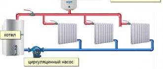
In any heating system consisting of several radiator batteries, their heating temperature depends on the distance to the heating boiler - the closer to it, the higher the degree. Therefore, for its efficient operation and to meet various requirements for heating the premises, a balancing valve for the heating system is built into the main line.
The construction market offers a wide range of these control valves, which have the same principle of operation and some differences in design. It is useful for any master or owner who independently carries out heating in his private home to know why a balancing valve is needed, the rules for its installation and settings to ensure the efficiency, economy and functionality of the heating main.
Rice. 1 Thermal imaging of a residential building with unbalanced heating
What is a balancing valve
To maintain the same temperature in the batteries, they are adjusted by changing the water flow - the less coolant passes through the radiator, the lower its temperature. You can shut off the flow with any ball valve, but in this case it will not be possible to set and adjust the same temperature in the devices if there is more than one heating device. It will have to be measured with temperature sensors on the surface of the batteries and by rotating the valve to experimentally set its desired position.
Balancing valves, which are widely used for adjustment, effectively solve the problem of maintaining balance automatically or through simple calculations of the required flow rate and the corresponding settings in the devices. Structurally, the device partially blocks the flow of the coolant, reducing the cross-section of the pipes, similar to any shut-off valve, with the difference that the required supply volume is accurately set on the adjustment scales using the rotary handle of the mechanism or automatically.
How to adjust radiator network balance
Each valve comes with instructions upon purchase, which contain information on how to calculate the number of turns of the handle.
Using the attached diagram, you can permanently regulate energy consumption, saving on heating.
According to the instructions, you need to turn the valve to a certain level.
There are two ways to adjust the valve.
Method 1
Experienced specialists have a simple and proven way to adjust the system.
They divide the valve speed by the number of radiators located around the entire perimeter of the room. It is this method that allows them to accurately determine the flow adjustment step. The principle is to close all taps in the reverse order - from the last to the first radiator.
For a more clear example, let's take the following system characteristics.
The dead-end system has 5 batteries, which are equipped with manual valves. The spindle in them is adjustable by 4.5 turns. It is necessary to divide 4.5 by 5 (the number of radiators). The result is a step of 0.9 turns.
This means that the following valves must open the following number of turns:
| First balancing valve | by 0.9 revolutions. |
| Second balancing valve | 1.8 revolutions. |
| Third balancing valve | 2.7 revolutions. |
| Fourth | 3.6 revolutions. |
Method 2
There is another, very effective way of adjustment. It is carried out faster, and includes the ability to take into account the individual features of each radiator. But to carry out such an adjustment, you will need a special contact-type thermometer.
The whole process proceeds in the following sequence:
- Open all valves without exception and allow the system to reach an operating temperature of 80 degrees.
- Measure the temperature of all batteries using a thermometer.
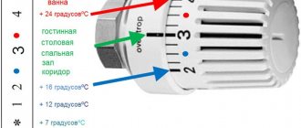
- Eliminate the difference by closing the first and middle taps. The latter mechanisms do not need to be adjusted. As a rule, the first valve turns a maximum of 1.5 turns, and the middle ones - 2.5.
- Do not make any adjustments for 20 minutes. After adapting the system, take measurements again.
The main task of this method, like the previous one, is to eliminate the difference in temperature at which all batteries in the room heat up.
A balancing valve is a type of special device that allows you to regulate the heating system, ensuring its hydraulic balancing. This setting is carried out in order to ensure in each branch of the system a constant value of coolant flow rate sufficient to supply the required amount of heat to each connected radiator. This allows you to eliminate the situation when some heating devices heat up more strongly, while others heat up less. Installing such devices on each circuit allows you to reduce heating costs by up to 30%.
However, to do this you need to know how to set up the balancing valve. Only when it is configured correctly can such a positive effect be achieved. Errors during adjustment lead to imbalance of the system and disruption of the normal heat supply to the radiators.
Why use it
Installing balancing valves in the heating system, in addition to maintaining the same temperature of the radiators, in an individual home brings the following effect:
- Precise adjustment of the coolant temperature allows you to set its value depending on the purpose of the premises - in living rooms it can be higher, in utility rooms, storerooms, workshops, gyms, and food storage areas, you can set it lower using balancers. This factor increases the comfort of living in the house.
- Changing the coolant flow using a balance valve regulator depending on the purpose of the premises brings a significant economic effect, allowing you to save on fuel.
- In winter, when the owners are absent, constant heating of the home is necessary - with the help of balancing valves, you can adjust the heating system with minimal fuel consumption and maintain a constant temperature in all rooms. This advantage also saves financial resources for the owners.
Rice. 3 Manual balancing valves for heating and hot water supply (DHW) systems in the house
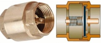
Types of valves and their design features
Today, there are two types of control valves, each of which has its own performance characteristics. Before buying a particular model, you need to carefully study their basic description. Most often, all specialists install the following balancing valves:
- Universal unit with automatic control system. A special feature of such products is that they completely control the heating system without human intervention. The functionality of the valve allows you to maintain a constant pressure difference between return and supply in a two-pipe system. As for single-pipe heating, the device controls the continuous flow of coolant. There are multifunctional models on sale that work perfectly in tandem with each other. The use of such units leads to changes in the flow rate and pressure difference in the pipeline. It is worth noting that the coordinated operation of such valves occurs thanks to a special impulse tube. The internal part of the automatic device is more like a piston pressure reducer. But they should not be confused, because they perform completely different functions.
- Manual valve. This device occupies a leading position in demand due to its affordable price and durability.
Any high-quality part must include o-rings, for example.
But among the main design features, experts note several nuances. The thing is that a high-quality part must consist of the following elements:
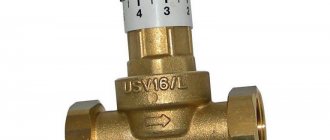
- Universal adjustment spindle. The main working part is presented in the form of a cone, screwed into a special saddle. At the moment the spindle is activated, the coolant flow is completely blocked.
- A cap that can be made of various materials, but most often of plastic. It is worth noting that metal products are considered to be of the highest quality and most durable.
- A durable brass body, which is equipped with all the necessary threaded pipes so that the user can connect the pipes. In the internal compartment of the device there is a special seat in the form of a small vertical channel.
- O-rings made of high quality rubber.
But the main feature of such a valve is that it is equipped with two fittings at once.
These units perform the following functions:
- They control the pressure level inside the system both before and after the valve.
- Provide reliable fixation of the capillary tube.
Each fitting necessarily measures the pressure level, and if during operation sudden changes in values were detected on the regulating mechanism, then the water flow is calculated.
Three-way valve for heating systems:
Design and operating principle
The principle of operation of balancing valves is to block the flow of liquid with a retractable valve or rod, causing a reduction in the cross-section of the passage channel. The devices have different designs and connection technologies; in a heating system they can additionally:
- Maintain the pressure drop at the same level.
- Limit coolant consumption.
- Shut off the pipeline.
- Perform drain functions for working fluid.
Structurally, balancing valves resemble conventional valves; their main elements are:
- Brass body with two through pipes with internal or external threads designed to connect to a line with standard pipe diameters. The connection in the pipeline, in the absence of a threaded fitting with a movable threaded nut (American), is made through its analogues - additional adapter couplings with different union nuts.
- A locking mechanism, the movement of which regulates the degree of blocking of the coolant passage channel.
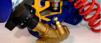
Rice. 4 Danfoss LENO MSV-B manual balancing valve
- Adjustment handle with scale and setting indicators, allowing you to adjust the flow inside the device.
- Modern models are equipped with additional elements in the form of two measuring fittings, with the help of which the flow volumes (throughput) are measured at the inlet and outlet of the device.
- Some models are equipped with a shut-off ball mechanism that allows you to completely shut off the flow, or have the function of draining liquid from the water supply.
- High-tech modern types can be controlled automatically; for this, instead of a rotating head, a servo drive is installed, which, when power is supplied, pushes the locking mechanism, and the degree of channel closure depends on the amount of voltage applied.
Rice. 5 Danfos AB-QM automatic balancers - design
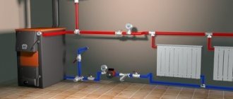
Installation and operation
The balancing valve is installed in accordance with the manufacturer's requirements. If there is an arrow on the body, the device is mounted in such a way that the direction of the arrow coincides with the direction of flow of the transported medium so that the valve can create the calculated resistance. Some manufacturers produce balancing valves that can be installed in any direction. The spatial arrangement of the rod is not important in most cases.
To prevent the valve from failing due to mechanical damage, a proprietary filter or a standard sump filter is installed in front of it. To eliminate unwanted turbulence, it is recommended to install valves on straight sections of the pipeline, the minimum length of which is indicated in the manufacturer’s instructions.
If the heating system is equipped with automatic valves, it should be filled through special filling fittings installed next to the valves on the return pipe, while the balancing valves on the supply pipe are closed.
Setting up the balancing valve is carried out using a table with indicators of pressure drop and coolant flow (attached to the device) or using a flow meter for balancers. But the initial calculation of flow rate and operational parameters must be performed at the design stage of the heating system.
Assembled balancing valve design
Types of balancing valves
Balancing in heating systems is carried out using two types of control valves:
- Manual . The design is a body made of non-ferrous metals (bronze, brass), which houses a balancing element, the degree of extension of which is set by turning a mechanical handle.
- Automatic . Automatic devices are installed on the return pipeline together with partner valves that can limit the flow of the medium by presetting the throughput. When connected, they are connected to partners via an impulse tube connected to the built-in measuring nipple. If the fitting is installed to supply water in a direct line, its handle is red; when installed in a return line, it is blue (Danfoss models). Automatic types include models controlled by a servo drive, which is supplied with constant voltage.
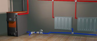
Balancing valve for heating system
Existing heat supply systems are conventionally divided into two types:
- Dynamic. They have conditionally constant or variable hydraulic characteristics, these include heating lines with two-way control valves. These systems are equipped with automatic balancing differential regulators.
- Static. They have constant hydraulic parameters, include lines with or without three-way adjustment valves, the system is equipped with static manual balancing valves.
Rice. 7 Balancing valve in the line - installation diagram of automatic fittings
In a private house
In a private house, a balance valve is installed on each radiator; the outlet pipes of each of them must have union nuts or another type of threaded connection. The use of automatic systems does not require adjustment - when using a two-valve design, the supply of coolant to radiators installed at a large distance from the boiler is automatically increased.
This occurs due to the transfer of water to the actuators through a pulse tube under lower pressure than that of the first batteries from the boiler. The use of another type of combined valves also does not require calculating heat transfer using special tables and measurements; the devices have built-in control elements, the movement of which occurs using an electric drive.
If a manual balancer is used, it must be adjusted using measuring equipment.
Rice. 8 Automatic balancing valve in the heating system - connection diagram
To determine the volume of water supplied to each radiator and, accordingly, balancing, an electronic contact thermometer is used, with which the temperature of all heating radiators is measured. The average supply volume per heater is determined by dividing the total value by the number of heating elements. The greatest flow of hot water should flow to the furthest radiator, a smaller amount to the element closest to the boiler. When carrying out adjustment work using a manual mechanical device, proceed as follows:
- Open all control valves all the way and turn on the water; the maximum surface temperature of the radiators is 70 - 80 degrees.
- Using a contact thermometer, measure the temperature of all batteries and record the readings.
- Since the furthest elements must be supplied with the maximum amount of coolant, they are not subject to further regulation. Each valve has a different number of revolutions and its own individual settings, so the easiest way is to calculate the required number of revolutions using the simplest school rules based on the linear dependence of the radiator temperature on the volume of passing coolant.
Rice. 9 Balancing fittings - installation examples
- For example, if the operating temperature of the first radiator from the boiler is +80 C., and the last +70 C. with the same supply volumes of 0.5 m3/h, on the first heater this indicator is reduced by a ratio of 80 to 70, consumption will go less, and the resulting volume will be 0.435 m3/h. If all the valves are not set to the maximum flow, but set to the average value, then you can take the heaters located in the middle of the line as a guide and similarly reduce the throughput closer to the boiler and increase it at the farthest points.
In a multi-storey building or building
The installation of valves in a multi-storey building is carried out in the return line of each riser; if the electric pump is far away, the pressure in each of them should be approximately the same - in this case, the flow rate for each riser is considered equal.
To set up in an apartment building with a large number of risers, it uses data on the volume of water supplied by an electric pump, which is divided by the number of risers. The resulting value in cubic meters per hour (for the Danfoss LENO MSV-B valve) is set on the digital scale of the device by rotating the handle.
What is it needed for?
A valve is an element of a heating system that allows the source of thermal energy to be evenly distributed throughout all rooms of a residential building. Since the coolant, following the path of least resistance, first enters the nearest risers of the building, and more distant risers, as a rule, have a lower temperature, the coolant simply does not reach them. To correct this situation, a balancing valve is used.
The valve serves to create artificial resistance along the path of the water. Thus, not the entire volume of water flows to the nearest area; the flow is distributed so that the coolant also flows to distant risers. In order to correctly install balancing valves, design organizations first make a hydraulic heating calculation. During the calculation, the difference between the upper and lower pressure values on each riser of the building is determined. Therefore, valves are also called differential pressure regulators.
Each valve is configured individually, taking into account the calculations made for the functioning of the system. Thus, the main purpose of the valves is to link together the circuits of the water heating system. The functions of the valve also include limiting water flow by consumer groups and balancing recirculation pipelines for hot water supply and heating and cooling ventilation systems.
Valve installation
When installing the valve, it is necessary to place it in the direction of the arrow on the body, which indicates the direction of fluid movement, to combat turbulence, which affects the accuracy of the settings. Select straight sections of pipeline with a length of 5 diameters of the device and its location points and two diameters after the valve. The equipment is installed in the return branch of the system; a plumbing adjustable wrench is sufficient to carry out the work; installation is carried out in the following sequence:
- Before installation, be sure to flush and clean the pipeline system to get rid of possible metal shavings and other foreign objects.
- Many devices have a removable head; for ease of installation in pipes, it should be removed in accordance with the instructions.
- For installation, you can use flax fiber with appropriate lubricant, which is wound around the end of the pipe and the battery outlet fitting.
- The control valve is screwed onto the pipe at one end, the other is attached to the radiator with special washers (American adapter coupling), which is placed on the outlet radiator fitting or screwed into the valve, playing the role of a connecting coupling.
Expert advice
Experienced installers of heating systems note that any adjustment work should be carried out on the basis of calculated data, which is especially important when drawing up project documentation. To prevent errors, you need to use a special valve diagram and measurements taken in advance. The adjustment process begins only when the handle rotates and the spindle moves. If the master does not have all the necessary measurements at hand, then the adjustment process itself will be considered conditional. In this case, efficiency and accuracy cannot even be discussed.
As for straight pipe sections that prevent water turbulence, their length must be at least 10 cm. If we are talking about an automatic device, then the main unit must have a fitting, which plays an important role in filling the circuit with the inlet valve closed.
Setting the balance valves
To balance the heating in a private house, select manual devices of the required diameter, selecting and configuring them using the appropriate diagram included in the passport. The initial data for working with the graph are the supply volume, expressed in cubic meters per hour or liters per second, and the pressure drop, measured in bars, atmospheres or Pascals.
For example, when determining the position of the adjustment indicator of the MSV-F2 modification with a nominal bore DN equal to 65 mm. at a flow rate of 16 cubic meters per hour. and pressure drops of 5 kPa. (Fig. 11) on the graph, connect the points on the corresponding flow and pressure scales and extend the line until the conventional scale intersects the coefficient Ku.
From the point on the Ku scale, draw a horizontal line for diameter D equal to 65 mm, find the setting with the number 7, which is set on the handle scale.
Also, for the selected diameter of the device, its adjustment is carried out using the table (Fig. 12), from which the number of spindle revolutions corresponding to a certain flow is determined.
Rice. 11 Determination of the position of the valve scale at a known pressure and a certain water supply
Rice. 12 Example table for manual configuration
Reasons for uneven heat distribution in rooms
Modern high-rise buildings and private houses are heated using a heating system consisting of radiators and piping. Both elements form one structure through which a flow of hot water spreads evenly to heat the living space.
However, despite the fact that the water supply pipes are made of durable metal, and professionals design the heating system, problems often arise with an uneven supply of hot water through the pipes. Additional reasons may also be low pressure, high water flow speed or a large amount of cold air inside the pipes.
Figure 1: Pipe pressure measuring device