A standard heating system includes many elements. Each of them performs its own task, as a result of which the design works smoothly and accurately. One of these elements is a heating check valve that controls the flow of coolant.
We will introduce all types of check valves used today in the organization of heating circuits. The article we presented describes their design features in detail and provides technical characteristics. Do-it-yourselfers will find installation manuals and valuable advice here.
Where is it installed in the heating system?
The general purpose of a check valve is to allow coolant flow in one direction and prevent it from moving back. They do not require power or any other conditions to operate; they operate from the movement of liquids. A check valve for heating is installed in all positions where backflow and parasitic circuits may occur.
In a heating system with several branches, a check valve is placed on the return pipeline. This prevents the pump from “pushing” the flow in the opposite direction.
The same devices are installed in cold and hot water supply. Those intended for heating are distinguished by the fact that materials are used that can withstand prolonged exposure to elevated temperatures. If there are rubber gaskets, then heat-resistant rubber is used. The same applies to plastic parts.
If we talk specifically about heating systems (HC), then a check valve is installed:
- To a bypass with a circulation pump in the piping of a solid fuel boiler - to ensure operation of the system in gravity mode (with natural circulation). In this case, models with the least resistance are installed, which operate easily and quickly - immediately when a flow from natural circulation appears. The function of the valve, in this case, is not to bypass the coolant when the pump is running.
- On the return pipeline when installing an indirect heating boiler. Why install a check valve in this case? To prevent the flow of coolant in the opposite direction when the circulation pump is operating.
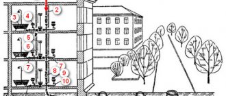
- With a branched heating system (for example, on several floors), on each branch. These check valves prevent the coolant from being “pulled” if one of the branches is turned off (when using one circulation pump).
- On the system's cold water make-up line. Here, in addition to the shut-off valve, a return valve is also needed. Since sometimes the pressure in the water supply is lower than in the heating system. Then, when opening the tap to refuel the system, without a check valve, the coolant will “go” into the water supply system.
Symbol of a check valve in the diagram
In the diagrams, the check valve is designated as two triangles with their vertices directed towards each other. One of the triangles is shaded. The installation location in the branch is almost any. The main thing is that it exists. The direction of flow is indicated by an arrow on the housing. The coolant flows in this direction. In the opposite case, it overlaps. When installing, carefully follow the arrow (you can also focus on the locking element).
From the laws of physics
Suppose that in radiators and a boiler the temperature of the liquid changes abruptly along the central axes: the upper parts contain hot liquid, and the lower parts contain cold liquid.
Hot water is less dense, which reduces its weight compared to cold water. As a result, the heating system consists of two communicating vessels, closed to each other, in which liquid moves from top to bottom.
The high column, formed by cooled water with a large weight, pushes out the low column upon reaching the radiators. As a result, the hot liquid is pushed and circulation occurs.
Operating principle of a check valve
First of all, it should be noted that check valves are not installed “just in case,” but only if necessary, if there is no other technical solution. This is due to the fact that the elements often have considerable hydraulic resistance, depending on the design. This introduces some restrictions when using check valves for heating with natural circulation. The reason is too low coolant pressure in the system.
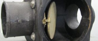
An exception is gravity valves with a rotary damper; some of their models are capable of opening the path of coolant at a minimum pressure of 0.001 Bar.
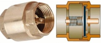
Despite the differences in design, most products are equipped with one key part - a spring. It is an actuator that closes the valve when normal conditions change; this is the principle of operation of the check valve. The force expended to overcome the elasticity of the spring determines the magnitude of the hydraulic resistance of the mechanism. For circuits with different operating parameters, products are selected that have the appropriate elasticity and massiveness of the spring.
What does the spring act on? Its task is to keep the locking device closed; this is its normal state. Then the fluid flow flowing from one side can overcome the elastic force of the spring, open the obstacle and move further along the pipe. An attempt to change the direction of the flow and flow in the other direction will lead to nothing - the shut-off device will slam shut, relying on the tide in the body. In this place there is a sealing element that makes the check valve in the heating system completely sealed.
Shut-off valves intended for use in heating circuits are made from the following materials:
- gray cast iron;
- steel;
- brass;
- stainless steel.
Rules for choosing a locking device
Choosing a check valve intended for a heating system is a responsible undertaking. If knowledge in this area is minimal, it is best to seek help from specialists. This will ensure that your new heating system is functional and safe.
You need to know that, regardless of their type, all check valves differ in the way they are connected to the pipeline.
Sleeve check valves are very easy to install. However, the threaded connection cannot withstand high pressure, so they have limitations in use
Coupling devices are equipped with a connecting threaded unit, which greatly facilitates their connection to the main line. Most often, such a unit is equipped with disc valves intended for installation in autonomous heating systems of an apartment or private house. Their distinguishing feature is their small diameter. Most often it is no larger than DU-50.
Flange products are a structure assembled on the basis of a part that has holes for fastenings. Using the latter, it is connected to the main pipeline. A flange connection is much stronger than a threaded connection.
For this reason, flanged valves are widely used in the construction of large-diameter pipelines. Ball type devices are most in demand.
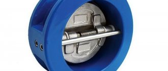
Wafer devices are designed for installation between two pipe flanges. They are lightweight and compact. Very often, both types of reed-type valves are produced in wafer design.
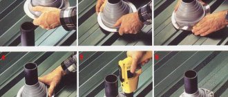
On sale you can find check valves that are installed by welding. This option can be used, for example, when installing heating from polypropylene pipes.
Flanged type check valves are securely attached to the pipe. This connection can withstand high pressure, which allows the devices to be used in centralized pipelines
Another important selection criterion is the material from which the device is made. It could be stainless steel. This option is considered optimal for highways with a diameter of less than 0.04 m.
The metal is practically not subject to corrosion processes and can withstand loads of up to 10 atm. This allows the valve to operate in the system trouble-free and for a very long time, but its cost is quite high. Brass valves have a lower price. They are subject to corrosion, but this process occurs very slowly, which significantly increases their service life.
However, their mechanical strength is much lower than that of stainless steel. Nevertheless, they can withstand the loads that arise in a household network quite easily. The most durable valves are made of cast iron - they successfully cope with critical pressure values, have significant dimensions and impressive weight.
Due to the nature of production, only body parts with a diameter greater than 40 mm can be made of cast iron. For this reason, they are used extremely rarely for the installation of autonomous heating systems.
It is desirable that not only the body, but also all internal elements of the check valve are made of metal. Plastic usually has less strength, which can lead to premature failure of the part.
When choosing a check valve, you need to remember one more rule - its diameter must exactly match the parameters of the passage hole. It is very important that the operating pressure of the system does not exceed the maximum permissible values for operation established by the manufacturer of the selected model.
Why is a check valve needed in heating systems?
When deciding where and how to install the valve, you should first of all take into account that its presence is undesirable in any system. The fact is that the device has a fairly high hydraulic resistance in the range from 0.1 to 1 meter of a horizontal pipeline section, which corresponds to pressure values from 0.1 to 1 atmosphere (bar).
The hydraulic resistance of a pipeline or fittings in the main depends on the flow speed (the volume of pumping); for household systems, the standard range of speeds of movement of the coolant is 0.5 - 1.5 m/s. With these values, the valve resistance is in the range of 0.3 - 0.4 m, which corresponds to a pressure drop in the line of 0.3 - 0.4 bar.
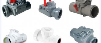
Types of check valve
Despite the fact that all devices of this type perform the same task, they have structural and, therefore, operational differences. Let's take a closer look at each of these types.
Disc type devices
A distinctive feature of the product is the presence of a disc valve. This is a plastic or metal element, the dimensions of which allow it to completely block the flow of coolant if it begins to move in the opposite direction.
The disk is connected to a steel spring. When a liquid moves forward, it is in a compressed state. When changing direction, it straightens and moves the disk from its place, thereby blocking the pipe.
The valve design also includes a sealing gasket, which allows the valve mechanism to sit as tightly as possible in the seat. Therefore, leakage is excluded in serviceable devices.
Connection diagram options
Before choosing a check valve, find out its purpose in your heating system. Let’s make the task easier and suggest options for using return valves:
- The valves are placed on separate circuits of a closed circuit, equipped with circulation pumps. The goal is to prevent the occurrence of parasitic flows that impair the operation of heating branches or boilers connected in parallel.
- When installed on a bypass parallel to the pump, the valve helps the system automatically switch to natural circulation mode when the power supply is suddenly cut off.
- Tapping into the make-up pipeline allows you to avoid emptying the heating network in various situations.
Important advice. Do not listen to the “experts” and do not place a spring valve in front of the only circulation pump in a conventional single-circuit system. Assurances that in this way you will protect the pumping unit from water hammer and other nonsense do not correspond to reality.
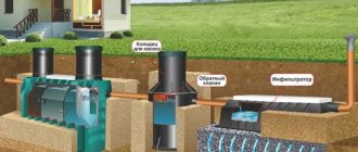
Piping diagram for 2 boilers - wood-burning and electric - using return valves.
As an example of the correct installation of check valves, we present a diagram for the joint connection of a solid fuel and electric boiler. If one of the pumps stops, the second will inevitably drive the coolant with a parasitic flow in a small circle. You can’t do without shut-off valves here.
Note. A similar situation may arise when connecting a radiator network and an indirect heating boiler with a separate pump without a distribution comb, hydraulic valve or buffer tank.
The second example is typical of gravity systems with natural circulation of water, converted to work with a pump. The main mode is forced, but when the light is turned off, the unit on the bypass will stop and stop pressing the actuating part of the check valve embedded in the direct line. Then the convection flow of water along the main line will resume until electricity is supplied.
Installing a check valve on the make-up is not necessary, but can save you from unexpected problems. A real example from practice: a homeowner decided to increase the pressure in the heating system and opened the feed tap in the boiler room. Since at that time the water utility company was repairing the network and cut off the water supply, the coolant transferred cold water and partially went into the pipe. Instead of refilling, there was emptying, as a result the pressure dropped and the gas boiler stopped.
Purpose
Why is a check valve needed in a heating system? To answer this question, let's consider a specific situation.
p, blockquote 2,0,0,0,0 —>
During the operation of the heating system, hydrodynamic pressure may form in some places, which will inevitably lead to a change in the direction of the flow of hot water. To avoid an emergency, you need to install a check valve on the bypass. The main purpose of this element is to prevent the reverse movement of the coolant.
p, blockquote 3,0,0,0,0 —>
Thanks to the check valve, hot water will circulate freely throughout the system. At the same time, he will not allow it to move in the opposite direction, and its technical and operational characteristics will remain unchanged. Choose a valve responsibly, because... It is very important to choose a suitable model; the safety and reliability of the entire heating system will depend on it.
p, blockquote 4,0,0,0,0 —>
Installing the valve correctly
To avoid making mistakes when choosing and installing a check valve in the right place in the heating system, listen to these simple recommendations:
- To avoid stray flows in adjacent branches, install petal or disc type products. The former are preferable because they do not create increased hydraulic resistance.
- In the bypass assembly of a gravity system, use a ball valve that has virtually zero resistance.
- For refilling, choose an element with a poppet valve designed for high pressure.
Products with gravity butterfly valves are always placed horizontally with the plug facing up - The gravity type reed valve is always mounted horizontally. Moreover, the head of the service nut must be vertical, otherwise the valve will not close and will begin to leak coolant in the opposite direction.
- Do not purchase fittings with a cast iron body. It is heavier and less reliable in operation.
- Check the correct installation by the arrow on the valve body indicating the direction of water flow.
- You cannot install fittings with a spring lock in a circuit with natural circulation - gravity flow will stop due to high resistance.
Disc and leaf valves require periodic maintenance and cleaning. If solids or deposits become trapped under the seat seal, the non-return valve will lose its seal. The best cleaning method is to remove the element and blow off the adjacent surfaces with a compressor.
Nuances of proper installation
During the installation of shut-off valves, several rules should be strictly followed:
- The valve is installed strictly in the direction of coolant flow. To avoid mistakes, the product body must be marked with an arrow indicating the working direction.
- Paronite gaskets can be used to seal connections, provided that they do not reduce the diameter of the passage hole. Otherwise, the valve will exert more hydraulic pressure than intended.
- The device must be installed so that other elements of the heating system do not exert additional pressure on its body.
- It is highly advisable to install a mesh in front of the check valve for rough cleaning. This will make it possible to prevent solid particles from entering the locking mechanism, which, in turn, can lead to a violation of the tightness of the device when closed. Or use special valves with mesh.
Another important point: before installation, you need to once again make sure that the valve is selected correctly.
For example, for schemes with forced circulation, any type of device is suitable, but for gravitational systems, only a rotary petal device without a spring. Since the coolant moving by gravity will not be able to cope with the resistance of the spring.
Advantages and disadvantages
A check valve with a filter helps prevent the plate from jamming in any position.
The check valve has advantages and disadvantages that are common to all types of devices. There will be no hot flow into the riser if cold liquid flows there. This extends the performance of system elements that are designed for a certain temperature. The devices are easy to install and do not create noise during the passage of liquid. Check valves solve the problem only in a specific area; additional control devices are installed for other circuits.
Some mechanisms allow the occurrence of water hammer when the flow passes through the working unit, but this feature of the valve only harms a system with a large diameter. The valves become dirty from the water flow if the system operates with an energy carrier without propylene glycol or other additives. In this case, the disc or plate may become stuck in the open or closed position.
How recharge works
Using the make-up unit, the missing coolant is added to the heating system. And it is added until the operating pressure is within normal limits. Usually the make-up is connected to a cold water supply. But you can power the heating system from the storage tank. You can supplement the coolant in three ways:
- Using manual mode. This mode is usually used in small heating systems. You need to control the pressure yourself using a pressure gauge. If necessary, open the appropriate taps. You can use a make-up pump to supply water. Or the water will flow by gravity.
- Using automatic refill. The heating system make-up valve is activated when the pressure in the system decreases. If there is a need, voltage begins to flow to the pump in parallel, and thus water is forced into the heating system. Once the pressure is within normal limits, the valve closes and the pump turns off. In an automatic make-up system there is no need to monitor all values. But in this mode, one more element needs to be supplied with electricity, which is a disadvantage.
- Manual recharge using a pump. The make-up unit is used not only to supplement the coolant, but also for other purposes:
- Discharge of water during repair work;
- First filling of coolant into the heating system;
- Flushing the system;
- Water softening or filtration;
- Crimping.