Heating devices with thermostats have to function in new conditions, as they begin to respond to almost any changes in the environment. When a signal about a change in temperature is received, the supply of coolant to the water heating radiators is promptly stopped or resumed.
In such cases, the operating pressure increases significantly and reaches a critical point, which is especially important for steel radiators, and the use of a bypass valve installed behind the circulation pump is required.
What is it and why is it needed?
A bypass valve, also known as an overflow valve, is a device that regulates the pressure in the system by bypassing or draining an excess volume of the working medium (gaseous or liquid) into another circuit. The peculiarity of the unit is that it is capable of doing this continuously, which differs from its safety analogue, which reduces the pressure in the pipeline by one-time or periodically removing the medium from it.
A similar pressure reducer, in contrast to the overflow unit, maintains a stable pressure of liquid in the flow following from it, while the overflow unit maintains a stable pressure before itself.
Specifications
*
The main quantities that determine the operation capabilities of bypass devices in the system:
- Passage diameter. Internal cross-section of the carrier passage through the valve. May differ from the diameter of the main circuit of the system.
- Bandwidth. Characterizes the volume of the working medium capable of passing through the valve per unit time at a nominal pressure of 1 atm. Measured in cubic meters/hour.
- Ultimate pressure. The maximum value of excess pressure for which the device is designed to operate. Exceeding this parameter in the system leads to displacement of the valve rod and the beginning of media bypass. Determined at a carrier temperature of 20 °C.
- Setting range. The limits of the possibility of adjusting the excess pressure at which the valve begins to open. The unit of measurement is bar.
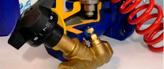
Adjustment scale with tuning slider
Bypass valve in the fuel supply system
The bypass valve in the fuel supply system is installed next to the fuel pump[3], and sometimes combined with it. It is designed to drain excess fuel supplied by the fuel pump back into the fuel tanks.[4] Thus, the bypass valve ensures the same pressure in the fuel supply system, regardless of engine operating mode.[5] The solenoid valve works in conjunction with the bypass valve to close it, thus sealing the high pressure circuit.[6]
Causes and Effects
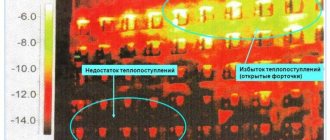
Often, an increase in the pressure level in such systems is associated with the normal functioning of thermal valves that are installed on radiators or a thermal head. When the maximum temperature set in manual mode is reached, the supply of hot coolant to one or another radiator is reduced, which ensures an increase in pressure, and in some cases even the whistle of the radiator shut-off valves.
Of course, this affects, in addition to the level of comfort in the room, also the performance and durability of the heating system and its individual components. To avoid such situations, professionals recommend equipping heating systems with thermostatic valves.
Equipping the system with bypass valves will enable its normal functioning and will guarantee stabilization of the pressure inside it.
Possible applications of bypass valves
In terminology, the ARI-PRESO bypass valve can be called a spring-actuated differential pressure control valve. This model is available in cast steel, stainless steel, ductile iron (as nodular cast iron is most often called) and gray cast iron. As for the functional features of ARI-PRESO, we note that not every product of this type can find such wide application. ARI-PRESO bypass valves are used:
- to protect pumping equipment. By connecting ARI-PRESO control valves in parallel to the pumps, the latter are reliably protected from sudden pressure changes;
- in heat exchanger lines and other consumption sources. In systems where thermal oil is used, ARI-PRESO valves provide a minimum circulating volume;
- for protection against excessive pressure drops in systems with increased productivity;
- in steam-condensate systems to maintain the required pressure level and prevent evaporation of the medium.
As for the areas of application of ARI-PRESO bypass valves , these are industry and production, heating systems and various technical installations. Media with which ARI-PRESO valves can work: various liquids and gases, including neutral ones, as well as water vapor. ARI-PRESO differential pressure control valves have a nominal diameter ranging from 15 to 100 mm and are designed to operate at temperatures from -60 to +450 degrees Celsius (medium temperature). The nominal pressure is 16 bar.
Types of bypass valves
Although the operating principle and performance characteristics are similar, the devices have additional differences.
Connection method
On small diameter pipelines (up to 150 mm), the inlet and outlet pipes are usually made with a threaded connection. Options - external or internal thread of the pipe. For large cross-section pipelines, connections are made by welding or using flange connections.
Large Diameter Flanged Valves
Flow direction
*
The valve installed in the main flow usually has an angular shape for connecting the outlet circuit. Valves included in the bypass line can also be direct-flow.
Direct Flow Bypass Valve
Active element
Typically, the outlet is blocked by a shutter or damper. But in some designs, the locking element is a diaphragm connected to a rod. The use of diaphragm options is recommended in pipelines with a working medium containing solid particles in addition to liquid or gas.
Mechanism of action
The difference in the method of influencing the shut-off element led to the emergence of two types of valves.
- Direct action. A simple mechanical device in which the coolant directly acts on the active element of the valve. Inexpensive and relatively easy to maintain.
- With elements of indirect influence. It actually consists of two valves. The small diameter valve works as a pressure sensor and, when activated, controls the main valve rod, which opens the drain into the bypass channel. Characterized by more precise adjustment of the response threshold.
Areas of use
The valve is used in pipelines where increased pressure of the working medium may occur.
In cars, it dumps excess exhaust gases that spin the turbine blades, thereby reducing the pressure in the intake manifold. This ultimately protects the engine from overheating and failure. In the fuel supply and cooling lines, it drains the excess generated under pressure into the fuel tank and expansion tank, respectively.
This fitting is widely used in heating and hot water supply devices, where it ensures the rational functioning of all heating devices and pipeline sections. In combination with balancing and other valves, the fittings act as a pressure regulator.
Purpose and areas of application
Bypass valves are installed in liquid and gas pipelines in which pressure may regularly increase for various reasons. The task of this device is to maintain operating pressure in the system. When the pressure increases in the section of the line in front of the installed valve, it releases part of the working medium into the bypass circuit, thereby reducing the pressure in the main system.
These devices are used in systems:
- cold and hot water supply,
- heat supply from any sources,
- cooling,
- conditioning.
A separate area is the automotive industry. They are installed in cooling and fuel supply systems. Bypass valves in turbocharged automobile engines regulate the air supply to the turbocharger.
Automotive engine turbine bypass valve
Differences from other types of safety valves
Other valves installed for the safe operation of pipelines have a similar device and principle of operation. But they differ in purpose and requirements.
| Valve type | Mechanism of action | Principle of operation |
| Bypass | Installed in a bypass circuit and redirects part of the flow into it | Constantly working as needed |
| Safety | Reduces pressure in the system, throwing part of the media out | In case of emergency pressure increase |
| Reducing | By changing its throughput, it regulates the pressure in the part of the main circuit located after its installation site | Full time job |
The bypass valve reduces the load on the system pumps without changing the amount of media in it.
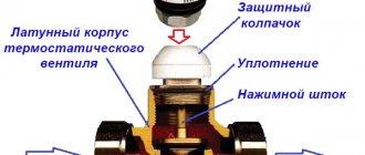
Design and principle of operation of any bypass valve
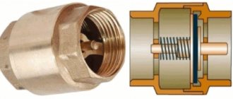
Its body is made of steel or brass. The main element of the internal mechanism is a shutter (flap) that closes the passage opening. The bolt is held closed by a spring. In some models, its role is played by a membrane or diaphragm. The spring force is regulated by an adjustment lever located on the outer surface of the housing.
Valve design diagram
*
The hydraulics of operation are based on the pressure of the working fluid flow in the pipeline on the valve located inside the housing. As long as the force is less than the lever set by adjustments, the drain hole remains closed. As soon as the pressure becomes greater than the setting pressure, the pressure on the spring leads to its compression. As a result, the drain hole becomes slightly open, and part of the flow is bypassed into the bypass circuit, reducing the pressure in the main hydraulic system.
Then the reverse process occurs - a decrease in pressure leads to the spring expanding and the valve closing, and the valve is again ready for the next reset. Pressure equalization occurs constantly, automatically. When the system operates in the “closed water valve” mode, the bypass channel remains constantly open, ensuring constant recirculation of the media flow through the bypass circuit.
Cross-section of the bypass device
Types of valves for boiler and bypass
To understand the installation and selection of an element for radiators, you must first find out what safety bypass valves exist and what function they are intended to perform.
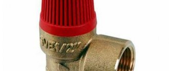
The operating principle of a thermostatic safety valve is quite simple and is as follows. The working medium (water) exerts pressure on the plastic area, which compresses the spring and opens the passage. But when the pressure exceeds 20 bar, the plastic plane reaches the rod, which opens the outlet to the outside.
This valve is mounted for radiators in heating systems on containers in which the liquid is under high pressure. An example would be electric boilers. The valves installed on electric boilers have a special hole to ensure local drainage.
Clutch fuses
They are a mechanism that is equipped with a double-sided thread and a gasket located on the outside. The device operates on the basis of a spring that holds the rod. After applying force, the rod, being pressed, opens the passage. When pressure builds up on the back side, the blocking provides more pressure.
These products are made from brass. The rod plate located inside is made of heat-resistant plastic, and the spring is made of stainless steel. The mechanism works due to the fact that water under pressure is supplied to the damper, which rises, clearing the way for the flow. When the pressure drops, the rod lowers, eliminating the possibility of flow returning.
Three way valves
A three-way valve in a heating system is necessary to allow the coolant to cool. They can have manual, electric and servo-driven mechanisms. They have a fairly simple design, with outgoing and incoming holes.
Flow regulation is provided by a special damper, which has the form of a rod or ball. When rotated, it orients the flow in the desired direction. Such a valve also belongs to safety valves mounted on circuits with low temperatures. For example, in places where radiators operating from a single heat source are adjacent to a heated floor.
They are used in places where it is necessary to lower the temperature in one part of the circuit. With its help, the temperature of heated floors is reduced in comparison with batteries.
Mixing of the working medium can be carried out in both manual and automatic modes. To operate the valve in automatic mode, it is necessary to equip the low-temperature circuit with special sensors, information from which will be supplied to the servo drive. Three-way valves are made from different materials, but the main ones for their production are cast iron and steel.
Four way valve
The four-way valve is often made of bronze. It has three holes, one of which is output and two are inlet. The regulating element in it is a corrosion-resistant rod.
When moving in the vertical direction, it does not completely block the flow of water, which makes it possible to redistribute the flows.
Heating systems and water heating devices experience constant changes in pressure and temperature during operation. Overheating or a sharp increase or decrease in the pressure of the working medium can cause breakdown of equipment or a pipeline unit and even a utility accident. To make the operating conditions of heating devices optimal and protect the heating network, devices are used that allow you to regulate the pressure of the coolant and maintain it at the required level - bypass valves.
Where to mount and why
The thermostatic valve is mounted by inserting it into the system at a short distance from the liquid supply pump, between the return and supply circuit. The mode for setting the maximum permissible pressure limit of the working medium allows the owner to make the settings manually.
Currently, the range of these products offered by the retail chain is quite large. But as practice shows, it is better to pay attention to such well-known brands as Mankenberg, Valtec, DANFOSS. They have proven in practice efficiency, reliability and durability in operation.
Purpose
Regulating thermostatic bypass valves are designed to ensure a stable pressure difference between the return and supply pipelines in closed heating systems. When the heat load decreases, the thermostatic radiator valves close. This leads to an increase in the pressure drop between the return and supply pipelines.
Using a bypass valve offers the following advantages:
- reduces the load on the pump;
- protects the boiler from rust;
- prevents the occurrence of noise unnatural for normal operation;
- increases the temperature of the working medium in the return pipeline.
By closing the thermostatic valves on the radiators, we will increase the resistance of our heating system (increase in the pressure difference between the return and supply pipelines). This will increase the load on the pump and lead to noise.
If the pressure reaches the maximum level, which corresponds to the settings of the bypass valve, it opens, forming an adjustable bypass. Also, a bypass valve is installed behind the circulation pump between the return and supply pipelines.
Mechanism
The design includes a metal body (cast iron, bronze, brass), inside of which there is a damper and a spring that activates it. The valve can be a spool valve, a plate, etc. Another option is a shut-off membrane with a rod. A handle is built into the body, which is used to adjust the device.
Devices used in large networks and large-diameter pipelines may contain a lever-load mechanism in their housing.
Bypass valve design:
Direct and indirect acting valve
Pressure control valves are divided into direct and indirect acting devices.
- The first type of valve has a simple design: a spring is driven by a shutter, which is directly pressed by the coolant. Such devices are inexpensive, easy to operate, reliable, insensitive to dirt, but not very accurate in settings.
- Indirect-acting devices, also called pulse devices, have a piston-actuated main valve, a smaller pulse valve, and a pressure transducer. When the pressure changes, the small valve presses on the piston, which moves the main valve, which regulates the throughput of the device. Thus, flow control occurs indirectly, in an indirect way. Valves of this type are less reliable due to the larger number of parts and are expensive, but they can be adjusted more accurately.
Selection tips and approximate prices
When choosing a bypass device, the consumer must be aware that it is designed to ensure normal operation of the system and constantly maintain stable pressure inside it.
Such a device must meet the following requirements:
- help reduce pressure, quickly redirect excess coolant volume to another circuit;
- have a sufficient range of adjustment;
- be suitable for the method of connection to pipes, for example, have a threaded connection for pipes with a diameter of ½′′.
The throughput device is selected, first of all, based on the type of working medium of the pipeline: gas, steam, water.
Next, they are guided by certain criteria.
Criteria
The main ones are:
- features of the actuator;
- pipeline type and configuration;
- valve material;
- device diameter (DN), which should not be less than the cross-section of the supply pipe;
- range of pressure drops supported by the device;
- damper capacity, characterized by maximum and minimum Kvs values;
- operating and maximum media temperature.
The specific operating pressure to which the valve must be adjusted is specified in the data sheet.
It is important to provide for correct installation, for which everything must be correctly calculated taking into account the parameters and configuration of the system. For example, in a complex heating structure, it is better to install an overflow regulator behind all pumps, and additionally use check valves to protect them.
You should pay attention to the reliability of suppliers so as not to run into counterfeit products.
The approximate price for bypass valves for domestic use varies from 1,700 to 5,200 rubles. Industrial designs equipped with measuring instruments, flanges, and a wide range of settings are much more expensive.
Thus, the overflow angle valve shown in the photo with DN ¾”, designed for 0.06-0.36 bar, with an adjusting head, will cost 1,680 rubles. It is installed to ensure normal operation of the pump. Drains excess coolant when the pressure in the radiators is exceeded into the return line.
If you have to purchase a bypass device for a car, you must take into account all the features of the previous one, and do not chase after cheap fakes.
Device selection criteria
Bypass valves are required in the following types of pipelines:
- Boiler storage systems. The water in them is under pressure, and periodic switching on/off leads to sudden changes in the volume and pressure of the flowing liquid.
- Continuous hot water supply systems equipped with temperature control devices. When the temperature changes, the volume of the medium in the line also changes. Constant adjustment and smoothing of pressure differences is required.
- Multi-circuit heating systems. When any of the circuits is turned off, the pressure in the remaining parts increases. Bypass devices minimize load changes on the system pumps.
- Solid fuel heating devices are not capable of sharply reducing the temperature of the medium after shutdown. Bypassing the flow line, the cooling time can be reduced.
When selecting a suitable bypass type safety device, the following parameters must be taken into account:
- Diameter and connection method allowing it to be included in a regulated line.
- The throughput must correspond to the calculated media outlet in case of maximum load.
- Operating temperature of the device and material of its manufacture.
- The need to adjust the valve actuation point. Its range should be within the planned pressure changes.
Focusing on products from a well-known manufacturer is also important.
Installation
The valve is installed in accordance with the installation instructions. Tips for proper installation of different types of automation:
- a strainer is installed in front of the overflow valve;
- pressure gauges are installed before and after the valve;
- the device is embedded so that its body does not experience mechanical loads of torsion, compression or tension associated with the operation of the connected circuit;
- It is better to select and install automation with the organization of straight sections in front of the valve (5DN) and after it (10DN);
- the overflow device is mounted on pipes located horizontally, inclined or vertical, unless the instructions contain other instructions in this regard.
The automation is configured after water is released into the main during the setup of the entire unit. It is possible to adjust the valve in an empty pipeline if there is an acceptable value.
The autovalve is regulated by creating the required differential at the location of the device; the screw is rotated until the valve opens. The difference is reduced and the moment of closing the damper is monitored, and the device is additionally adjusted. The pressure changes smoothly due to the fact that each revolution of the screw corresponds to a clear range of pressure changes.
The operation of the valve is checked by changing the pressure drop at the installation site. The accuracy of adjustment and the speed of opening of the damper are checked. The error is allowed within 10% at the limit values. The set pressure corresponds to the opening moment; full expansion is achieved at values of higher pressure drop.
Maintenance is done once a month, the setting pressure indicator and the speed at which the damper begins to open are checked. The operation of the bypass valve is checked by changing the pressure at its location. The filter is cleaned depending on the degree of contamination, as evidenced by pressure gauge readings.
Subscribe to our channel and you will not miss many more useful articles! And visit us on the website trubyda.ru.
Installation features
*
The specific installation location of the bypass device depends on the layout and type of pipeline. The valve can be integrated into an additional diverter circuit. For closed-cycle heating systems, excess pressure is released into the return pipeline. It can also be used as a safety valve, adjusted to emergency pressure and with liquid discharge into the sewer system.
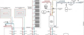
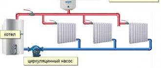
In a single-circuit heating main circuit, the bypass valve is installed in the bypass outlet after the injection pump.
Bypass valve for local heating system. Installation diagram.
For greater safety and security of the entire heating circuit, it is advisable to install additional ones in addition to the bypass device:
- check valve to prevent reverse flow direction,
- air vent valve for bleeding air pockets,
- drain valve to completely drain the media from the system,
- for small-diameter cottage-type systems - mesh filters.
In multi-circuit systems, bypass valves are installed in each circuit.
Turbochargers with mechanical bypass valve.
Waste Gate, or translated into Russian, is a turbine bypass valve, a little-studied and unknown element of a car’s turbocharger, which, despite the undeserved lack of attention, plays an important role for the turbine and the entire engine as a whole.
The bypass valve rotates due to exhaust gases. The air flow passes through the hole in which the impeller is located, the blades of which rotate due to the strong flow of gases. The impeller rotates, spinning the turbine compressor, after which pressure is generated in the intake manifold. Pressure is measured in the amount of air that passes through the turbine.
The flow rate of the discharged exhaust gases depends on how hard the engine is working. That is, the more you press on the gas pedal, the more exhaust gases there will be, accordingly, the impeller will rotate more strongly and, naturally, the pressure will be greater. If this pressure is not controlled, then during intensive movement the turbine will hang it so much that the engine simply cannot withstand it. It is for this purpose that the turbine bypass valve serves, which, roughly speaking, bleeds off excess exhaust gases after reaching the pressure required for the turbine. Budget-class cars often use an internal bypass valve, in which exhaust gases leave directly from the turbine housing itself. There are also modifications when an external bypass valve is placed in front of the turbine inlet, for this purpose a cross pipe is installed or part of the exhaust manifold is replaced.
The internal bypass valve has a slightly larger hole through which the exhaust is discharged. The internal valve is equipped with a flap that closes the hole when the turbine is running (the required pressure is built up). The damper can be open or partially open, it is connected to a lever connected to the activator lever.
What is an activator? This is a kind of pneumatic device that, using a diaphragm and a spring, converts pressure into linear movement. The activator uses a lever to open the damper, partially or completely, depending on the need.
Boost boost controllers (solenoids)
In front of the activator there is a special device called a solenoid, it is capable of changing the pressure that is supplied to the activator, as a result the solenoid “deceives” the activator by giving out not the pressure that actually exists, but the one reported by the solenoid. Therefore, if the pressure before the solenoid is 13 psi, then after the solenoid it is 10 psi, as a result the bypass valve, which is ready to be activated already at a pressure of 12 psi, will be inactive until 15 psi. This will open the bypass valve at at least 12 psi, but the actual pressure will be ~15 psi.
The solenoid operates by using the duty cycle of a small mechanism. When the operating cycle changes, it becomes possible to control the air flow through the solenoid. The control is carried out by a computer that analyzes the pressure and, guided by certain algorithms, makes a decision to increase or decrease the boost by opening or closing the bypass valve.
How is the bypass valve draft adjusted?
The lever has its own mount on which it moves freely. If this is not the case and movement is limited or difficult, there is a problem that needs to be corrected. It happens that the movement of the lever is intermittent, this is especially noticeable when heating. The activator rod can have different lengths, this allows you to adjust the degree of opening and closing of the bypass valve. If it is necessary to shorten the bypass valve rod, the end is tightened; if it is necessary to perform the opposite action, everything happens exactly the opposite. The shorter the pull, the tighter the valve will be closed, while the activator will require much more pressure to open the valve. The higher the pressure, the more the turbine will spin, and the bypass valve, in turn, will not be able to open as quickly.
If you use a feedback controller that can independently measure and control, adjusting the bypass valve draft will not achieve the same result that can be obtained without feedback. The reason is that the controller “takes into account” the changes that have occurred, therefore, such an adjustment will not give a significant result. In addition, a good electronic controller is capable of keeping the bypass valve closed at an activator pressure of 0 psi until the required pressure is reached, resulting in a much faster increase in pressure.
External bypass valve
An external bypass valve is a separate device designed to operate outside the turbine, that is, in a separate housing. These types of bypass valves are most often used for higher air flow. As a rule, they have a double activator, which allows the valve to open much faster, thereby providing better control over the state of turbine spin-up.
External bypass valves are designed for powerful cars from 400 hp. With. and higher, so if your “steel horse” has such power, installing an external bypass valve will be the only right decision for you. Gases can be discharged from an external bypass valve either into the exhaust or directly outside.
Tips for setup and maintenance
Installing a valve with adjustment of the excess pressure range is worth it to those who already have experience in calculating the required value. The opening of the drain hole begins at the pressure selected by the setting. But it usually opens completely at a pressure exceeding the initial value by 20%. But the calculation cannot be based only on this indicator, because such a decrease in the operating pressure in the system is nonlinear. Relieving part of the carrier already leads to a reduction in the load on the valve shutter. Therefore, to accurately calculate the throughput of devices, they are guided by the diagrams given in the data sheet.
It should be taken into account that the setting error of most regulators is 10%. For initial adjustment and subsequent monitoring, it is recommended to install pressure gauges before and after the bypass point.
The adjustment itself is carried out either by moving the slider along the scale or by rotating the adjusting screw. After setting and checking the required value, the screw is secured with a clamping nut.
Routine maintenance of the bypass valve consists of monthly monitoring of the initial response pressure and its opening speed. You also need to monitor the condition of the filters.
If the valve does not operate correctly, it should be dismantled, disassembled and all parts washed. Perhaps the malfunction is caused by a simple clogging of the mechanism.