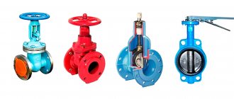
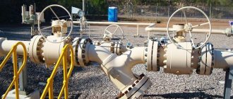
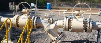
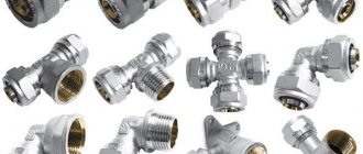
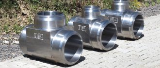
For pipelines for different purposes, different types of shut-off valves are used. In order to correctly select a device for a particular pipeline system, you need to know the purpose of the fittings and its technical characteristics. Let's look at the main types of locking devices in more detail.
Pipe fittings for blocking the flow
Locking devices: classification and application
The main types of shut-off valves for pipelines are valves, valves, flaps, taps and valves. Gate valves are characterized by the movement of the locking element at right angles to the longitudinal axis of the pipe, while valves are characterized by parallel movement.
Valves
It is possible to use valves on shut-off products with a diameter of up to 0.3 m. They are often used in the final (dead-end) sections of the system during repairs. The locking element, often a body of rotation or part thereof, rotates around an axis located at an arbitrary angle relative to the axis of the pipe. Valves can be used not only as shut-off valves, but also as control valves.
Valves
Gate valves are short-length shut-off elements designed to operate in systems with low hydraulic resistance.
By design, they are wedge (with a composite, elastic, solid wedge) and parallel (gate). In systems with low pressure, valves of the latest type are used.
The main purpose of valves is to perform locking functions; in most cases they are not used as regulatory elements. During operation, the valves can be set to two possible positions: closed or open.
It is best to use such elements in full-bore systems, that is, in the absence of a reduction in the cross-section of pipes in the nozzles. For example, valves are ideal for use in main pipelines where the working fluid moves continuously and at high speed.
A distinctive design feature of the valve is the presence of a spindle, which, depending on the design, extends or not.
As already noted, there are two main types of valves: gate valves and wedge valves.
The design of the gate elements includes a metal wedge that, when moving, cuts foreign elements of the working environment. Gate valves are equipped with pipelines for fecal wastewater, pulp and paper production, etc.
If it is necessary to carry out periodic repairs of system elements, wedge valves are installed, consisting of a cast-iron body, inside of which a rotating spindle connected to the wedge is installed. Wedge valves are used when servicing systems for transporting gases and liquids that do not react with the pipeline material. The body and cover of such products are welded from parts cut from corrosion-resistant or carbon steel sheets.
Valves
The purpose of the valves is to open and close under certain conditions, for example, when a certain pressure level is reached or the direction of movement of the working fluid changes.
Products are divided into single- and double-saddle, and usually the second type is used in production, which simultaneously performs distribution and control functions.
Based on the direction of flow of the working medium, valves are divided into angular (the direction changes by 90°), through (the direction does not change) and straight-through (the line of movement of the medium is straightened).
To completely block the flow inside the pipes, shut-off valves are used. This fittings ensure maximum reliability and tightness of the system.
If there is a need to prevent a change in the movement of the working medium (for example, if the pump fails and the carrier channel is damaged or broken), check valves are used.
With the help of control valves, you can control the amount of liquid or gas supplied to the system by changing the size of the inlet.
Shut-off and control valves, as the name implies, perform two functions simultaneously.
Cranes
A more universal option for pipeline fittings is taps. They can be used as shut-off, control or distribution devices. The taps are suitable for any, including viscous, liquids and gases. Repairing these devices requires a lot of effort and experience.
Valves consist of a valve (or plug) of spherical, cone-shaped or cylindrical geometry, with a hole in the center, and a body. These locking elements are made from brass, bronze, cast iron and steel, and in the case of more aggressive internal conditions - from porcelain or special plastic.
Cranes are usually divided into groups depending on:
- direction of flow and number of nozzles (through, three-way, angled, multi-pass);
- the principle of shutter movement (with spin, or lifting, or with rotation, without lifting, shutter);
- control method (manual, with electric, pneumatic, hydraulic drives);
- shutter geometry (needle, cone, ball, cylindrical);
- method of ensuring tightness (stuffing or tension).
Product advantages
The shut-off valve has the following advantages:
- A design that is completely suitable for repair in the event of any part failure.
- High operational reliability and tightness of the ceiling.
- The opening speed of the passage is sufficiently low, which eliminates the possibility of harmful hydraulic shocks in the system.
- Some models can be used to throttle the flow.
- It does not require great physical force to be operated by operating personnel. This eliminates the need for long levers in manually operated valves and an expensive electric drive in automatic models.
Kinds
Classification of parts for stopping the flow of gases and liquids is carried out according to various factors. Types of shut-off valves according to connection method:
- flanged;
- Waferless.
The shape of the flanges can be triangular, square, round.
Pile of shut-off valves
Gate valve
A type of shut-off valve that is installed on main pipelines. The main technical element is the spindle. It can be fixed or retractable. Gate valves may differ in technical characteristics and resistance to aggressive environments.
The question may arise - what is the difference between a valve and a damper. In this regard, the main differences lie in the smaller number of parts on the dampers. Thanks to this, they are less likely to break.
The valves are not made from materials resistant to chemicals. Because of this, they are used only to create water supply systems. Dampers must be used to move chemicals.
Valve
A shut-off valve is a body with two pipe fittings, in which there is a lock that moves using a threaded connection. When the valve rotates, the rod and flywheel move, which block or open the flow of the working medium. They can shut off the water supply and regulate the flow of liquid or gas.
Ball valve
It is a cast body, which has threads on both sides for connection to pipes. To block the flow, there is a handle with which you can change the position of the shutter valve. Additionally, a rubber gasket is installed under the handle.
Cranes are:
- multi-pass, pass-through.
- manual, equipped with electric drives.
The bolt can be moved by pressing or twisting.
An additional feature of the tap is adjusting the supply of gas or liquid. They are made of steel, cast iron, bronze, plastic, porcelain.
Valve
The most common device used to shut off pipelines. The position of the damper can be adjusted using the handwheel. Expensive models are equipped with electric drives. Most often they are installed on sewer systems. Not suitable for working with liquids with temperatures exceeding 50 degrees Celsius.
Gates
The shutter is the main part of any closing mechanism. If it is faulty, the liquid or gas will destroy the pipeline. More often they are made of steel or cast iron. The most common are butterfly valves.
Butterfly valve
Installation of expansion joints
a - lens with a valve; b - rubber-fabric; 1 - lower casing; 2 - upper casing; 3 - pin; 4 - coupling; 5 - nozzle; 6 — cap; 7 - small carpet; 8 — pillow under the carpet; 9 — reinforced water and gas pipe; 10 — welded flange; 11 - valve; 12, 14 — gaskets; 13 — two-lens compensator
Due to the fact that there is very often water in the wells, the nuts and coupling bolts rust, so working with them becomes difficult, and in some cases, operating personnel leave the coupling bolts on the lens compensators without removing the nuts. The lens compensator ceases to perform its function, so new compensator designs do not provide tie bolts. During repairs, a clamp is used to compress expansion joints.
Due to the fact that the expansion joints are made of thin-walled steel with a thickness of 3-5 mm, they cannot be of equal strength to the pipe. Limited pressure is the main disadvantage of lens compensators. To increase the permissible pressure, expansion joints are made of stronger steel, with more waves, but less height.
There are expansion joints made of bent, usually seamless pipes (U-shaped and lyre-shaped). The main disadvantage of such compensators is their large dimensions. This limits their use on large diameter pipelines. In gas supply practice, bent expansion joints are not widespread and are not used at all as installation expansion joints when installing valves.
Rubber-fabric compensators have great advantages (figure above). They are able to perceive deformations not only in the longitudinal, but also in the transverse directions. This allows them to be used for gas pipelines laid in mining areas and in earthquake-prone areas.
Industrial shut-off valves for pipes - what are their features?
Due to the fact that pipe fittings in the form of a finished product must fully comply with all safety requirements and regulatory documentation, in most cases only large enterprises are engaged in its production. In order to produce these elements on an industrial scale, you need the ability to control the process remotely, automatic operating mode and the highest possible reliability.
Here another classification of reinforcement appears. So, according to the scope of its operation it can be:
- general technical;
- industrial plumbing;
- for use in special conditions;
- ship/transport;
- industrial special.
Products of the first category are produced mainly in series and can be used in all possible areas. As for fittings intended for operation in special conditions, they are used in power systems with increased technical characteristics, and also in cases where transport routes for aggressive or toxic substances are being repaired/installed.
Special requirements are put forward for transport/ship elements. They are manufactured taking into account the size and weight of the products, as well as other parameters, including the possibility of use in different climatic zones. Finally, industrial special products are designed and created to order for specific organizations and departments.
Compensators.
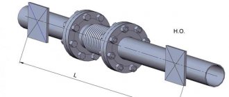
During the operation of gas pipelines, the temperature change can reach several degrees, which causes stresses of several tens of MPa. Therefore, to prevent the destruction of the gas pipeline from temperature influences, it is necessary to ensure its free movement. Devices that ensure the free movement of pipes are compensators - lens, lyre-shaped and U-shaped. On underground gas pipelines, lens compensators are most widespread (figure below).
Types of pipeline fittings
Despite the variety of types of devices related to the fittings of pipeline systems, experts distinguish four main types. The assignment of fittings to one type or another is carried out taking into account the structural features of the equipment. They can be expressed in the direction of movement of the locking/regulating element in relation to the direction of movement of the transported substance.
- Gate valve
characterized by the perpendicular movement of the locking/regulating element relative to the axis of movement of the liquid or gas through the pipeline system.
- Valve
- This is a type of device with a locking/regulating element that can move parallel to the axis of movement of the substance transported through the pipeline system. Experts recommend avoiding the name “valve” in relation to fittings of this type, as this term may have several ambiguous interpretations.
- There is a locking/regulating element in the faucet
rotates around its axis, while making translational movements. The working element of crane-type equipment has the shape of a body of rotation and can move at different angles to the direction of the axis of movement of the working medium.
- The butterfly valve has a locking/regulating element
rotates around an axis located at a certain angle to the axis of the direction of flow of the substance that is transported through the pipeline system. The difference between this type of fittings lies in the working element, which has the shape of a disk.
All of the above types of fittings can be structured into individual components. For example, based on the shape of the seats and gates, wedge and parallel gate valves are distinguished (they have a retractable or non-retractable stem/spindle).
Depending on the shape of the valves, valve-type pipeline fittings are also divided into several types. There are disc and needle valves (they have a cone shape). Single or double seat valves are also available.
Pipe fittings such as a tap can be conical, spherical or cylindrical in shape of the working element.
Different types of fittings have their own advantageous characteristics and certain disadvantages. Depending on such characteristics of the device, each type of fittings has its own scope of application.
For gate valve type devices, the distinctive parameters are:
- significant construction height (distance from the horizontal axis of the pipeline system to the top of the spindle (rod/drive) when the device is fully open);
- small construction length (distance from one external end connecting plane to another);
- low hydraulic resistance;
- significant force on the shutter drive;
- slow response;
- increased wear of the seat surface when used in pipelines transporting liquids with high levels of contamination.
It should be noted that valves are more preferable when used as shut-off valves.
The most common type of pipeline fittings are valves. Their distinctive characteristics are as follows:
- small construction height;
- significant construction length;
- fast response;
- high hydraulic resistance with a high level of sealing.
Valves are used in many control devices.
Crane-type fittings combine the characteristics inherent in valves (face-to-face height and response speed) and gate valves (short face-to-face length).
For butterfly valves, the characteristic features are:
- small construction height;
- short construction length;
- low force on the shutter drive;
- fast response;
- low hydraulic resistance parameters.
Lens compensator
1 - pipe; 2 - flange; 3 - shirt; 4 - half lens; 5 - rib; 6 - paw; 7 - nut; 8 - thrust
Lens compensators are made by welding from stamped half-lenses. To reduce hydraulic resistance and prevent clogging inside the compensator, install
a guide pipe welded to the inner surface of the compensator on the gas inlet side. The lower part of the lenses through the holes in the guide pipe is filled with bitumen to prevent the accumulation and freezing of water in them.
When installing the compensator in winter, it is necessary to stretch it a little, and in summer, compress it with tie rods. After installation, the rods must be removed. Compensators, when installed next to valves or other devices, provide the ability to freely dismantle flange fittings and replace gaskets (figure below).
Types of shut-off valves
The following types of shut-off pipeline valves are distinguished:
- taps;
- gates (valves);
- valves;
- flaps.
Crane classification
Shut-off valves are primarily designed for low-pressure domestic pipelines.
The shut-off valve design is as follows:
- frame;
- locking element;
- handle;
- set of sealing gaskets.
Elements included in the stopcock
Devices can be classified according to several criteria:
- type of locking element;
- installation method.
An element that blocks the flow of a passing medium can be:
- ball. In accordance with this, the valve is called a ball valve (figure above);
- cone in the form of a plug (plug valve).
Plug type stopcock
The taps can be attached to the pipeline:
coupling method. The fixing nuts are screwed onto the thread prepared on the pipe;
Threaded tap
- flange method. The fixing elements are flanges connected to each other with bolts;
- welding method.
Devices mounted on flanges and by welding
Each tap has its own symbol. The markings on the device body must include:
- nominal diameter (DN);
- conditional pressure for which the device is designed (PN);
- material used to make the tap;
- manufacturer;
- additional reference materials (date of manufacture, batch number, etc.).
Symbols of the main parameters of the crane
If you know the markings, you can always choose a locking device yourself.
Using Gates
A shut-off valve (valve) consists of a body with two ends for attaching the device and a seat that is closed by a shutter.
Pipe shut-off valve
The main distinguishing feature of a valve from a faucet is its high tightness class, which allows the device to be used on gas pipelines.
A valve, like a faucet, can be connected to a pipeline using couplings, flanges or welding.
Valves are produced that are actuated by:
- flywheel (manual control);
- electric drive (electronic control), including using a remote control.
The marking of shut-off valves also contains:
- symbol of the device model;
- passage;
- designation of the type of connection to the pipeline;
- pressure;
- execution material;
- Climatic performance;
- document on the basis of which the valve is manufactured.
Designation of valve parameters
Purpose and types of valves
The most commonly used element of any pipeline is the valve. The device consists of a body and a cover, between which the shutter is located.
The simplest type of shut-off valves
The purpose of shut-off valves - valves - is any pipelines whose diameter varies from 15 mm to 2000 mm.
The advantages of the device, compared to other types of shut-off valves, are:
- ease of maintenance and design;
- small sizes;
- low resistance.
Gate valves can be made from the following materials:
- become;
- cast iron;
- non-ferrous metals and alloys made from them.
The valves are controlled:
- manually (rotating the handle);
- electric drive;
- hydraulic drive.
Valves with electric or hydraulic drive are mainly installed on industrial pipelines.
The designation of shut-off valves (valve) determines:
- type and name of the device;
- nominal working diameter;
- maximum pressure in the system;
- type of drive;
- position of the device in working condition;
- accommodation category;
- Climatic performance;
- type of connection of the device to the pipeline.
Designation of valve parameters
Purpose of dampers
The closing element in the damper is a disk that rotates around an axis.
Type of shut-off valves for pipelines
Valves are mainly used on pipelines that have a large diameter and are under low pressure, since the tightness class of the device is quite low.
The damper can be controlled:
- a flywheel that drives the axis of rotation (manual control);
- hydraulic drive;
- electric drive.
In most cases, the body of the locking device is made of cast iron, and the rotary disk is made of steel.
Dampers are installed:
- welding method;
- flange fasteners.
The valves can be used in chemical pipelines and sewer systems. They are practically not used for water supply or heating.
The brand of shut-off valves - valves, as well as the batch number, diameter, pressure and area of definition are indicated on the device body similarly to the previously given diagrams.
Valves
a - parallel with a retractable spindle: 1 - body; 2- locking discs; 3 - wedge; 4 - spindle; 5 - flywheel; 6 — stuffing box; 7 - sealing surfaces of the body; b - wedge with non-retractable spindle: 1 - wedge; 2- cover; 3 - bushing; 4 - nut; J - flywheel; 6 — oil seal; 7 - collar; 8 - spindle
When closing the valve, the wedge rests on the bottom of the valve and pushes the disks apart, which create the necessary density with their sealing surfaces. In wedge valves, the side surfaces of the valve are not parallel, but oblique. Moreover, these valves can be with a solid shutter or a shutter consisting of two disks. It is advisable to install parallel valves on underground gas pipelines.
However, valves do not always provide a sealed shutdown, since the sealing surfaces and bottom of the valve often become dirty. In addition, when operating valves with the shutter not fully open, the discs wear out and become unusable.
All repaired and newly installed valves must be checked for tightness with kerosene. To do this, the valve should be installed in a horizontal position and kerosene should be poured on top; on the other side, the valve should be painted with chalk. If the valve is tight, there will be no kerosene stains on the valve.
On underground gas pipelines, valves are installed in special wells (figure below) made of precast reinforced concrete or red brick. The well cover must be removable for ease of disassembly during repair work.
Storage conditions for shut-off valves and their installation
If the shut-off valve for pipelines is equipped with rubber seals or is a ball valve, it is stored slightly open.
Shut-off valves with metal gaskets are stored exclusively closed in order to prevent the entry of small mechanical debris. Before installation, valves must be located in a closed, dry room, without drafts or access to light.
Installation of shut-off valves is carried out through sequential technological processes. High build quality, durable and uninterrupted operation are achieved when installation is carried out by qualified craftsmen with impressive experience in this field.
For each type of part there are its own rules, which are established by factories for the production of shut-off valves in order to comply with them during installation:
Butterfly valves are mounted with the disc opening at 25%. Damage to the gasket should not occur if sufficient space is left between flanges of equal diameters. All nuts should be tightened gradually, and there is no need to install another gasket between the body itself and the flanges. Check valves must have the same diameters as the mating flanges. The installation distance between the valves, the correct flow direction, and the pulsation mode are strictly controlled. Knife gate valves require checking the position indicator first. During installation work, the flow direction and the required location of the knife valves are observed. After the hydrostatic test, monitor for leaks and adjust the bolts if necessary. The ball check valve requires special attention in low pressure applications and in horizontal installations. To effectively counteract pressure differences in the system, it is possible to install a ball with a directional skew. A single-leaf check valve is lowered between the flanges with a hook, which, when the valve is perpendicular to the pipeline, should be positioned vertically. Double check valve is not suitable for installation with decreasing flow
Before installation, be sure to check the functioning of the springs.
A ball valve is never secured with a vice and requires care when tightening connections. It is not advisable to tamper with the structure of unused shut-off valves, since each valve is tested in production with compressed air and water to ensure the correct assembly of all parts of the valve. Date: September 25, 2021
Cast iron valve with pressure lubrication
1 - channels; 2 - base of the plug; 3 - bolt; 4 - ball valve; 5 - gasket
In addition to lubricated valves, simple rotary valves are used, which are divided into tension, gland and self-sealing valves. These valves are installed on above-ground and on-site gas pipelines and auxiliary lines (pulse and purge gas pipelines, condensate collector heads, inlets).
In tension taps, mutual compression of the sealing surfaces of the plug and the body is achieved by screwing the tension nut onto the threaded end of the plug, equipped with a washer.
To create tension in the plug, the end of its conical part should not reach the washer by 2-3 mm, and the lower part of the inner surface of the body should have a cylindrical groove. This makes it possible, as the valve plug wears out, to lower it lower, tightening the shank nut, and thereby ensure tightness.
Dampers
These products are used in communications with cross-sections up to 2200 mm. Let's look at the main advantages of using dampers:
- ease of installation;
- repair of shut-off valves of this type is quite simple;
- light weight;
- compactness;
- easy to control;
- reasonable price.
Helpful information! In most cases, the dampers are adjusted manually, however, some models are equipped with hydraulic or pneumatic actuators in production.
There are dampers that are electrically adjustable. Such models are used in communications, the cross-sectional indicators of which vary from 300 to 1600 mm, and the pressure of the working medium is approximately 1.0 MPa.
Pipeline structures transporting water are equipped with special wafer valves that are capable of operating at a pressure of 1.0 MPa. Such models are equipped with a rubber sealing ring, through which the necessary sealing properties are achieved. Models that are manually adjusted are mounted on the pipeline in any position, and models that are remotely adjusted are installed with an electric drive upwards.
In addition to the flange method of connecting this product to the communication, there is also a welding method. These devices are made of cast iron or steel.
Conclusions useful video on the topic
You can learn how to maintain shut-off valves on a gas pipeline from the following video:
The design features of wedge and hose valves will be discussed in this video:
All gas pipelines are considered high-risk objects, so the choice of gas fittings and equipment should be taken seriously, and, if necessary, consult with specialists. Only high-quality gas shut-off valves can ensure ease of maintenance, speed of repair, and high tightness of pipeline components.
If you have questions about the topic of the article, or can add interesting information to our material, please leave your comments in the block below.
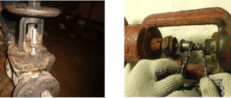
Causes of breakdowns
Let's get acquainted with the most common causes of shut-off valve failures. The reasons that cause valve failures include debris that gets inside the pipeline during installation. It settles on the sealing rings, cutting grooves there that violate the tightness. This can be prevented by thoroughly flushing the main networks before using them. Failed valves are repaired in special workshops equipped with lapping machines. They remove the damaged layer from the sealing rings, returning them to their previous properties.
After the repairs have been made and the bolts have been tightened, before the shut-off valves are installed, the valve undergoes hydraulic bench tests under pressure. If the tests are completed successfully, an acceptance certificate is issued.
Selection principles
Before purchasing pipeline fittings, you need to draw a drawing of the pipeline. Calculate the number of connection points for household appliances and connection points of individual elements. When choosing, you need to consider some factors:
- number of worker threads;
- level of stability of the working flow, possible water hammer, pressure surges;
- operating temperature.
Advantages and disadvantages
Positive sides:
- creating sealed connections between individual pipeline elements;
- the ability to connect household appliances, new circuits;
- Using connecting parts, you can protect the line from pressure drops.
Automatic parts allow you to regulate the work flow without human intervention.
Rubber seals wear out over time, resulting in poor sealing.
Fittings for the water supply system (Photo: Instagram / integrat_engineering)
Wellhead piping diagrams
3.1. Wellhead piping diagram No. 1
The scheme is used when working on wells with reservoir pressure not exceeding hydrostatic pressure, when the possibility of oil and gas manifestations remains.
3.1.1 When working with a universal wellhead seal (UGU-2), to prevent oil and gas seepage through pipes, a shut-off arrangement shown in the diagram (item 8) must be used, which must be subject to the following
requirements:
— the ball valve of the shut-off arrangement must be in the open position.
— the ball valve is closed after the ram valves are closed.
— the length of the remote pipe must be determined so that the circular groove of the sealing coupling is at the level of the valve (in the absence of a centralizer).
3.1.2. When work involves changing electric centrifugal pumps, there must be a device for cutting cables on the site. Cable cutting in the event of an oil and gas show must be carried out in close proximity to the plug.
3.1.3. When installing according to scheme No. 1, in order to prevent work on dismantling the APR in the event of a gas-propelled gun, it is recommended to use UGU-2-140.
3.2. Wellhead piping diagram No. 2
The scheme is used for work related to the development, capital and ongoing repairs of wells with reservoir pressure equal to or exceeding hydrostatic pressure.
3.2.1. The blowout preventer equipment configuration contains one preventer equipped with rams to match the diameter of the drilling or tubing pipes used.
3.2.2. When work involves changing electric centrifugal pumps, there must be a device for cutting cables on the site. Cable cutting in the event of an oil and gas show must be carried out in close proximity to the plug.
3.2.3. Especially for wells with ESP, it is possible to use a prefabricated pipe-cable preventer, which eliminates cutting of the cable during an oil and gas show (only when using a flat cable of the KPPBPS type).
3.2.4. The preventer is controlled directly at the wellhead. The working platform must provide convenient and unobstructed access to the preventer control wheels.
3.3. Wellhead piping diagram No. 3
The scheme is used for perforation, stimulation of the formation with geophysical injection and other work related to the descent of geophysical cable, when working on gas wells, wells with a gas factor of more than 200 m3/m3
3.3.1. This scheme is a combined one, providing for work on raising and lowering tubing and drill pipes according to scheme No. 2.
Before starting geophysical work, the well must be equipped according to scheme No. 3, after which the installation is checked for tightness and a report is drawn up. After completion of geophysical work, the wellhead equipment with blowout prevention equipment must be brought into compliance with diagram No. 2.
3.3.2. The layout of the blowout preventer equipment must contain two
preventer. The lower preventer is equipped with blind rams, the upper preventer is equipped with dies to match the diameter of the drilling or tubing pipes used. The preventer with pipe rams is equipped with a remote control.
Instrumentation and automation devices in gas pipeline systems
In addition to all of the above, numerous instrumentation and automation devices (instruments and automation) are used in gas pipeline systems.
In addition to gas fittings, instrumentation and control systems are installed on gas pipelines. This allows for constant monitoring of the condition of the equipment and the progress of the technological process. And also quickly identify pre-emergency and emergency situations
The most popular devices used in gas systems are:
- gas alarms;
- equipment for emergency shutdown of incoming gas;
- equipment for measuring the volume of gas passed through;
- electronic regulators of the gas volume passed;
- autonomous power supplies;
- gas valves for automating various processes and optimizing the operation of pipelines;
- gas regulators for regulating the volume of medium passing through some section of the pipeline.
Such devices are high-tech equipment used in a wide variety of conditions.
