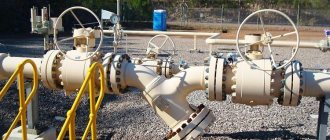
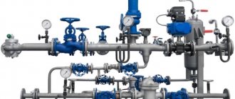
A pipeline network for any purpose is a serious engineering structure in which each part bears a certain functional load and is responsible for the quality, safety, and uninterrupted operation of the network. But the main line does not consist of pipes alone; fittings are also needed. The design solutions of such parts vary in complexity, material of manufacture (steel, cast iron, brass, plastic), types and purpose. It is used for steel, metal-plastic, polyethylene, polypropylene systems. A wide range of these products are classified, which helps to understand the question of pipeline fittings: what is it?
Each pipeline is equipped with different types of valves - shut-off, control, etc.
Classification
Pipeline transport is the leader among other wheeled and non-wheeled vehicles in the transportation of goods. The total length of all Russian highways is more than 250 thousand kilometers.
To manage such a national heritage, special technical means are needed, which are pipeline fittings. It comes in 3 types:
- plumbing;
- industrial;
- laboratory
Rice.
1 Types of pipeline fittings Plumbing fittings include devices intended for adjusting and shutting off the water supply systems of apartments, houses and private enterprises. These are valves, taps, mixers and other devices.
The working medium is a liquid, gas, pulp or other substance flowing through a pipe.
Laboratory fittings include devices that operate in limited conditions without exposure to pressure and high temperature. All kinds of bosses, tubes, protective frames necessary for making accurate measurements, sampling and other laboratory manipulations.
Industrial valves include devices that control the working environment. Management means:
- stop;
- redirect;
- adjustment.
Adjusting the medium in a pipe involves monitoring and changing (if necessary) its main parameters (pressure, temperature).
The fittings are divided into general industrial and special. Each industry produces its own special pipeline fittings, with certain parameters and design. These devices are needed:
- utility workers;
- gas workers;
- oil workers;
- fireboxes;
- chemists;
- shipbuilders.
At the “requests of all those in need,” valve manufacturing plants produce specific products that perform a specific task.
Application
Pipe fittings are used in pipelines, boilers, tanks and other industrial devices. Needed for regulation/control of liquid and gaseous media, such as:
- hot/cold water (fresh and salt);
- water vapor;
- petroleum products;
- diesel fuel, gasoline;
- natural and synthetic oils;
- natural and associated gases;
- chemical industry substances;
- sludge and pulp.
For each sector of the national economy, specific devices are produced that have individual operational and technical parameters. For example, for shipbuilding, fittings are used that have relatively compact overall dimensions due to cramped conditions. But for the chemical industry, the main factor is the operation of the device in aggressive environments.
What materials is it made from?
Various materials are used to produce pipe fittings. GOST R 55509-2013 specifies the requirements for the composition of the metals used. Cast iron used:
- gray SCh15, SCh20;
- malleable KCh30-6;
- with spherical graphite VCh40, VCh45.
The metal alloys used are:
- carbon steel, alloyed, high-alloyed;
- non-ferrous metals and alloys - bronze, brass, titanium alloy, aluminum, nickel.
Plastic products are widely used, these are polyvinyl chloride, polyvinyl chloride, polyethylene. Used to transport aggressive substances.
Tip: Recently, Walraven star Quick plastic clamps with a ratcheting actuator, which speeds up the installation process, have become increasingly common.
Types of industrial fittings
Species classification is needed to clearly distinguish the nature of the work and the functions performed. In accordance with this, the following subgroups of pipeline fittings are distinguished.
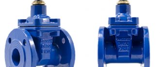
1. Shut-off (in Figure A). Completely shuts off the flow of gas or liquid. It is placed at the boundaries of pipeline sections, in front of tanks, boilers and other units.
2. Reverse (B). Prevents the substance from flowing in the other direction. Protects units, pumps and stations from the adverse effects of reverse current.
3. Safety (B). Protects units and components operating under pressure. Does not allow the basic parameters of the working environment to be exceeded, discharging excess into the environment.
4. Regulating (G). Serves to adjust the basic parameters, changing the flow rate, pressure, pressure by changing the flow rate.
5. Disconnecting (D). Blocks the flow of substance when basic parameters are exceeded.
There are also combined models of pipeline fittings that combine several functions at once.
Fig.2 Types of industrial fittings
According to the principle of influencing the working body, which performs one or another adjustment function, the valves can be controlled and autonomous.
Autonomy in the general understanding is a characteristic of a system whose behavior does not depend on external factors, but is determined by its internal foundations. In relation to fittings - automatic action from the working environment.
Autonomous fittings include:
- reverse;
- safety;
- disconnecting.
To the controlled one – shut-off and regulating. The latter may also provide for automatic triggering by the substance. To do this, a sensitive sensor is installed in it, which “decides” when it is necessary to intervene.
In terms of the volume of devices supplied to enterprises that manage pipeline systems and highways, the 1st and 2nd places are occupied by shut-off and check valves. By design, these types are the simplest and most reliable.
What other types of pipeline fittings can there be?
There are also a number of other characteristics by which pipeline fittings are classified:
- By purpose and area of application.
This is the most extensive classification of equipment for pipeline systems. Depending on the characteristic operational characteristics, vacuum, cryogenic, cut-off (with a short response time) and other types of valves are distinguished. Equipment for piping systems may also differ in the location of installation or the presence of special options (heated devices).
The most significant characteristics that are used to classify valves include their purpose (controlling, anti-surge, pressure reducing pipeline devices, etc.).
The sale of pipeline fittings is in demand in various industries. Depending on the application, such devices may have different requirements. Thus, fittings for pipeline systems for gas transportation must provide a high level of sealing (this requirement is determined by the explosion hazard and flammability of the working gaseous medium). Valve devices used in pipeline networks for transporting oil and petroleum products must have high anti-corrosion properties. This is determined by the aggressiveness of the working media used in the petrochemical industry.
- Upon connection to the pipeline.
Depending on the installation method, flanged, wafer-type or wafer-type devices are distinguished (the latter type is mounted in the middle of the flanges of the pipeline network). A characteristic feature of coupling devices is the presence of internal threads and connecting pipes. One of the elements of pipeline fittings that are installed by welding is also the presence of special connecting pipes for welding with the pipeline network. The fittings are named after their main feature – connecting fittings.
- According to the design and shaping of the body.
Depending on the location of the connecting pipes of the pipeline fittings, one can distinguish through-type devices (connecting elements have parallel axes) and corner equipment. In turn, pass-through fittings can also be classified into several types. These are partial bore (the cross-section of the passage is less than the cross-section of the connecting pipe at the inlet of the fittings) and full-bore devices (the cross-section of the passage is greater than or equal to the cross-section of the connecting pipe at the inlet of the fittings). Depending on the assembly method, pipeline fittings can be cast, welded, stamped, stamp-welded, cast-stamp-welded, etc.
- By type of seal.
If the device has special gland seals that provide the necessary tightness of the working elements, then this serves as a sign of gland fittings for pipeline systems. In the absence of such a seal, they speak of sealless devices (membrane and bellows type products).
A fairly extensive list of requirements is imposed on control and shut-off pipeline equipment, which leads to a wide variety of valve designs. In some cases, such requirements may even conflict with each other, so when choosing pipeline equipment it is necessary to be strictly guided by existing classifications.
Drive unit
Pipeline fittings are available with 3 types of drive mechanisms:
- manual;
- mechanical;
- remote.
The manual drive is made in the form of a steering wheel, handle or valve, and depends on the type and size of the device. To control such fittings, direct human participation is required.
The mechanical drive is represented by a gearbox operating from the direct influence of personnel, as well as an automatic device operating from the control environment.
The control medium is the energy that acts on the drive that sets the gate in motion.
The valve is the main part of the fittings, directly with the help of which the device fulfills its purpose.
There are 2 types of remote drive.
1. Manual - the valve is moved by human action on the actuator located remotely from the valve. In this case, the drive is connected to the device through transmission (chains/cables, shafts, bearings, gears).
2. Automatic. The system contains a command environment, which is transmitted from a single control center to an automatic device installed on the valve.
The command medium is a signal that activates an automatic drive.
Let's get acquainted with each type of drive in detail.
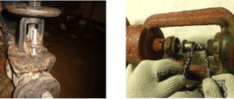
Manual
When pipeline fittings are equipped with a manual drive mechanism, the valve is driven by a steering wheel (flywheel).
Fig.3 Manual drive options
Figure 3 shows that the designs of manual mechanisms are different. For example, a massive steering wheel is installed on the valve, with which you can move the valve to the lower or upper position by moving the nut and spindle. There are handles on the faucet and the butterfly valve, which, when acted upon, close their shut-off organs.
The choice of drive type depends on the dimensions of the valve, the principle of force transmission from the handle and the nature of the movement of the shutter. On a valve, force is transmitted through the threaded connection of the nut and spindle, and the shut-off element moves perpendicular to the flow of the working medium from the steering wheel.
But on the tap and bolt, the force is transmitted directly from the handle. The constipation organs are located differently here:
- at the faucet, the spherical valve is located in the duct and rotates around its axis;
- in a butterfly valve, the disk is also in the flow and rotates around its axis perpendicular to the flow of the medium.
The larger the diameter of the passage of the fittings, the greater the hydraulic resistance exerted on the valve. This results in the necessary effort that a person must apply in order to block the pipe. With high levels of hydraulic resistance, it is very difficult to move the shutter to the “closed” position using a manual drive.
Mechanical
Drives of this type come with an actuator in the form of a reduction gearbox and an automatic device.
Rice. 4 Mechanical drive options
In addition to the types of mechanical drives shown in Figure 4, there are electromagnetic and hydraulic drives.
The mechanical gearbox plays the role of a speed-reducing device. The advantage of this type is the ability to work on large-diameter fittings without the cost of a control medium (energy). But there is also a drawback: by lightening the required load on the steering wheel, the number of revolutions to completely block the flow increases. And this entails loss of time.
The operating principle of an electric drive is similar to a mechanical gearbox, with the exception of the presence of a motor. It acts on the spindle, opening and closing the bolt in a matter of seconds. To reduce the required power of the electric motor, a reduction gear is additionally installed. But since on a standard 220 V device, with a standard current frequency of 50 Hz, the number of revolutions on the shaft reaches 3000, a reduction gear is necessary here.
The operating principle of pneumatic and hydraulic drives is similar, with the exception of the control medium. In the first case, the rod is driven by air pressure, in the second - by water.
The rod is a movable part without a thread that transmits force from the drive to the valve.
Installation of pneumatic and hydraulic actuators is carried out on shut-off valves, which require immediate operation.
Remote
This type of drive is necessary to speed up the operation of the line, as well as when installing fittings in places where it is impossible to quickly access.
When servicing thousands of kilometers of oil and gas pipelines passing through “rivers and oceans,” installing a remote drive is a necessary necessity.
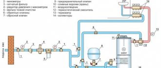
Rice. 5 Remote drive
Figure 5 on the left shows a diagram of a manual remote drive. Using the flywheel (1), the operator transmits torque to the chain drive (4). Through a system of chains (shafts) and rotary gears (3), torque is transmitted to the valve steering wheel (5), which, in turn, communicates movement to the valve, blocking the flow.
This system is used in cases of installation of pipeline fittings in cramped areas (technological hatches, compartments cluttered with pipes, production premises, etc.)
The figure on the right shows the valve control panel. In this case, the drive is controlled remotely, from the dispatcher’s office. The remote control has buttons for opening/closing the shutter and fault warning lights.
Additionally, locking handles are installed, when activated, it is impossible to control the drive with the opening/closing buttons. This safety measure is used when carrying out work on the main line, which is accompanied by depressurization of the system. The locking handle eliminates the human factor, which is often the cause of industrial accidents.
Autonomous drives
Drive mechanisms of this type are used on shut-off, check valves, protective and safety valves. The autonomous drive can be designed as:
- double-leaf disc springs;
- burst disc;
- shutter springs, etc.
The principle of operation of an autonomous drive is as follows: when certain parameters of the working environment are reached and under its influence, the valve automatically operates. For example:
- when the direction of flow in the pipe changes, the bivalve disk closes the flow;
- when the pressure rises to a critical level, the membrane ruptures;
- When the flow rate or pressure increases, the valve spring is retracted.
The action of this drive occurs from the influence of the environment on the working part of the valve without human or other (energy) intervention.
Method of moving the working mechanism
Depending on the method of movement of the working mechanism, the following types of pipeline fittings are distinguished:
- Cranes are locking elements with a body of rotation, the movement of which is carried out by movement around its axis. Can be positioned arbitrarily in relation to the direction of flow.
- Valves are elements that regulate or block the direction of flow by moving across the main flow.
- Gates or dampers are elements made in the form of a disk that can rotate around its axis perpendicularly or at an angle to the flow.
- Valves are parts in which locking and regulating elements are mounted on a spindle. When they move back and forth parallel to the flow, the cross section in the horizontal plane is blocked. The working medium for such fittings can be liquid or gaseous. Valves come in valve and ball types.
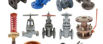
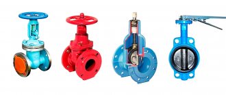
Types of fittings
The easiest way to understand what pipeline fittings are is to become familiar with their types. But these pipeline products are used on modern highways:
- gate valves (available with retractable and non-retractable spindle);
- valves (gates);
- butterfly valves;
- check valves;
- valves (ball, cone);
- dampers;
- steam traps.
Each type has an individual design, standard size, operating principle, drive, sealing method, and other features.
Rice. 6 Types of fittings
The material of body parts and shut-off elements depends on the working environment (its main parameters) for which this or that type of valve is intended.
Shutter type
There are several types of shutters:
- sheet;
- disk;
- wedge;
- plate;
- elastic membrane;
- hose valve
The first 3 types of valves are installed on gate valves. Regardless of the type of gate, its movement occurs perpendicular to the current of the medium. To ensure a certain degree of tightness, the sealing surfaces of the valve are made of different materials.
The sealing surface is the contact part of the disk (wedge) and the housing ring, which provides a given degree of tightness.
Tightness is the property of fittings to prevent the spread of medium in separated pipes (cavities).
Rice. 7 Wedge gate
A gate valve with a leaf gate is called a gate valve.
The wedge differs from the disk in the relative position of the seal. Accordingly, at the wedge they are located at an angle to each other, and at the disk they are parallel.
The design of the wedge valve can be:
- hard;
- elastic;
- composite.
In the rigid version, the wedge fits tightly into the provided housing seat.
Seat - a recess in the lower part of the valve body in which sealing rings are installed, which can be cast or pressed with interference.
The elastic design allows the discs to be mutually installed in the saddle. If there are inaccuracies in the processing of seals in the valve, the elastic core makes it possible to smooth out this defect.
A composite wedge made of two disks works in a similar way. The mobility of the elastic and composite structure reduces the quality requirements for processing (scraping) the sealing surfaces.
Scraping is the process of processing sealing surfaces to give them precise mutual geometry.
For especially critical pipelines transporting hazardous chemicals, precision electromechanical processing of seals is carried out. Such valves have a high tightness class.
Disc-shaped
This type of valve is installed on valves. Unlike the shut-off element of a valve, a disc valve moves parallel to the medium current.
The disc valve is more durable than the wedge valve. It's a matter of the nature of the movement. If in a valve the wedge moves along the sealing surfaces of the rings in the body, then with the plate there is no such movement. Due to the absence of friction of the seals, the disc valve retains its geometric parameters and the declared tightness class longer.
Fig.8 Disc valve
Valves are used for pipelines of relatively small diameter (up to 250-300 mm). This is due to greater hydraulic resistance to the plate than that of the valve.
Diaphragm and hose
A diaphragm valve is a structure whose shut-off organ is made of elastic rubber reinforced with metal plates or other elastic material.
The hose valve is made of inserts into the passage hole of a reinforced rubber tube with a high degree of elasticity. The current is blocked by compressing this tube through external mechanical action.
Diaphragm and hose fittings are used in chemical industry pipelines. Elastic rubber is made of aggressively resistant materials.
Valves are used for pipelines of relatively small diameter (up to 250-300 mm). This is due to greater hydraulic resistance to the plate than that of the valve.
Fig.9 Diaphragm valve
In addition to the listed types of valves, there are also ball, cone and cylindrical.
Valve tightness class
This parameter is determined after the manufacture of each specific device, experimentally on special equipment. This procedure is regulated by GOST 9544.
In accordance with the standard, valves are classified into classes from A (no leaks) to G. Devices intended for use at critical facilities correspond to classes A, AA, B, C.
Table 1 Tightness standards
Q – indicates the amount of leakage (volume measured in cubic mm per second).
Design features
The main design features of pipeline fittings include:
- body design;
- pipe design;
- body shaping.
Let's analyze each parameter in detail.
Housing design
Pipeline fittings can perform the function of turning the main line. For this purpose, devices with angular nozzles are produced. The standard angle is 900. For each individual enterprise, according to its order, factories produce non-standard rotation angles.
Ordinary, straight fittings are called feedthrough fittings. In such a device, the centers of the connecting pipes are on the same line.
According to the diameter of the duct, the fittings can be full bore or partial bore. For example, if the passport indicates a nominal bore diameter of 300 mm, then for a partial bore device the internal diameter will be 250 mm. For full bore, the internal diameter, respectively, is 300 mm.
The internal diameter refers to the size of the flow area of the housing seats.
Not all full-bore devices have an internal diameter equal to the declared parameters in the passport. For example, for a valve with a nominal diameter of 350 mm, the size of the flow area can be from 331 mm to 350 mm. Such parameters of full bore valves are regulated by valve engineering standards. This cross-section range is within tolerance.
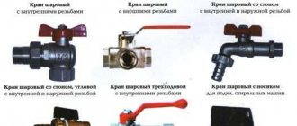
Pipe design
The inlet and outlet openings of the fittings are called branch pipes. For a hermetically sealed connection of the device to the pipeline, the fastening method must meet the standards.
And here are the ways in which the pipes are connected to the pipeline.
1. Flange. It has the shape of a disk with grooves and holes for fastening with bolts.
2. Pin nut. It has an internal thread on one side, and on the other, a hole for an internal fitting with fangs.
3. Clutch. Has internal threads on each pipe.
4. Fitting. An ordinary smooth or ribbed tube of smaller diameter than the bore.
5. Welding connection. The pipe has a special edge groove for welding work.
In industrial pipelines, the most common fastening method is flange and weld connection. These two types of fastening can withstand the heaviest loads and have excellent tightness, reliability and durability.
The fitting is used to connect hoses to valves. To improve the tightness of the connection, a clamp is used.
Couplings are most often found on plumbing fixtures. But the pin method has a limited scope of application. It is installed on fire hydrants, taps and hoses.
Shaping
According to the method of forming the body, the fittings are:
- cast (parts are made by casting into molds);
- cast-welded (cast parts are joined by welding);
- stamped-welded (stamped parts of the body are welded together);
- lithostamp-welded.
Electric arc welding is used to connect the body parts of the fittings. On the production lines of manufacturing plants, special machines equipped with computer control (CNC) are installed.
Stamping of body parts occurs under powerful presses. To do this, the heated blank is placed in a mold. Under the influence of the load from the press, the blank receives the required parameters.
The choice of one or another forming method depends on the grade of metal.
Methods for connecting fittings to pipelines
There are several ways to connect fittings: coupling, nipple, welding, fastening, flange, pin, fitting.
Classification of industrial pipeline fittings according to the method of connection to pipelines. The following types of fittings differ, depending on the methods of attachment to the pipeline:
- Coupling method. Connection using a coupling with internal thread.
- Nipple method. Attaches using nipples.
- Welding method. This method is carried out using welding. This method has both a large number of advantages and disadvantages. The advantages of the method are high-quality welding of fittings, guaranteeing the reliability of all connections. This method will not require subsequent additional maintenance, for example, there will be no need to tighten the flanges as when making flange connections. The disadvantages are that welding during work can lead to certain problems.
- Tightening method. Fastening is done using studs and nuts.
- Flange method. Connections are made using flanges. This method has its advantages and disadvantages. Among the advantages, it should be noted the repeated installation and removal of fittings, the strength of the connections made, as well as operation in situations where different ranges of passages and pressures are used. Among the disadvantages are loose fastenings, which leads to loss of tightness of connections, and large dimensions and weight.
- Tsapkovy method. The fittings are connected to the pipeline via an external thread for a seal with a collar.
- Fitting method. Attached using fittings.
Metal for body parts
Pipe fittings are made from:
- cast iron;
- become;
- brass;
- aluminum;
- nickel;
- titanium.
Fittings used in utility pipelines are usually made from GGG40 or 50 cast iron. This is gray nodular cast iron. In addition to this alloy, malleable and high-strength cast irons are used in valve making. Various additives to the alloy provide the reinforcement with:
- heat resistance;
- acid resistance;
- alkali resistance;
- and antifriction properties.
Castings of housings, steering wheels and valves are made from cast iron.
Become
Steel has better (than cast iron) strength characteristics. Since steel is ductile, it is used for the manufacture of critical structures operating under high pressure.
Plasticity is a characteristic of a metal, which is expressed in the ability to equalize force stresses caused by external influences (pressure of the working environment).
For the manufacture of body parts, carbon steel, grade 25L or 35L, is used.
Valves in contact with the working environment are made of alloyed alloys with the addition of titanium, nickel and chromium. Thanks to the anti-corrosion properties of these additives, the seals have excellent resistance to corrosion, mechanical stress and fatigue.
Non-ferrous metals
Plumbing valves and taps are mainly made from brass, copper and bronze. Bronze and brass alloys are also used in cryogenic fittings operating at extremely low temperatures (less than -1530C). As the temperature of the working environment decreases, the mechanical and strength properties of brass increase.
Since brass has excellent antifriction properties (abrasion resistance), it is used in the manufacture of moving parts (for example, a running nut).
Titanium serves as an additive in alloy steels, which are used for surfacing sealing surfaces.
Classification, labeling and standard requirements
Pipeline fittings, due to their ability to change the internal cross-section of the pipeline, make it possible to effectively control the flow of various types of media. Thus, its use makes it possible to perform the following operations:
- distribute the phases of movement of working media;
- reset the flow;
- turn off the supply;
- provide mixing of several streams;
- adjust flow parameters;
- distribute the work environment.
The classification of fittings is based on its functionality. So, depending on this parameter, pipeline fittings can be of the following types.
Regulating type
With the help of such pipeline fittings, the flow parameters of the working medium and, accordingly, its main characteristics are changed. In this category, throttle and shut-off and control types are distinguished. With the help of the first type of fittings, which are often called pressure-reducing fittings, it is possible to reduce the working load in the pipeline, which is done by increasing the hydraulic resistance in its flow zone. Shut-off and control pipeline valves are a set of devices that help regulate the parameters of the working flow and shut it off.
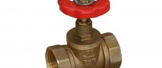
Shut-off valves for different pipe diameters
Locking type
Such pipeline fittings are used to hermetically shut off the flow of the working medium. If it is used to control the flow of the working medium into control and measuring units, then it is called control. There are also drainage shut-off valves, due to which the working medium is discharged from pipelines or containers.
Mixing and distribution type
Such pipeline fittings ensure mixing of working fluid flows, as well as their distribution along the required directions of movement.
Protective
This pipeline fittings are used to protect system elements from the consequences caused by changes in the flow parameters of the working medium. Such changes can most often be the consequences of emergency situations in the system. Fittings of this type can also provide protection against changes in the direction of movement of the working flow.
Phase separation
This is a pipeline fitting that divides the working environment into different phase states. For example, it can separate superheated steam and the working environment, retain condensate (condensate trap), and also solve a number of other problems.
Safety
This type of pipeline fittings protects the system from a critical increase in pressure in the working environment.
» data-lazy-type=»iframe» src=»data:image/gif;base64,R0lGODlhAQABAIAAAAAAAP///yH5BAEAAAAALAAAAAABAAEAAAIBRAA7″>
Pipeline fittings, according to the requirements of State Standard R52720-2007, are characterized by two main parameters:
- conditional pressure;
- conditional pass.
Conditional pressure, designated Ru or PN, characterizes the value of this parameter at which tanks or pipelines can be operated for a certain period of time, provided that the temperature of the working environment is +20 degrees Celsius. The classification of pipeline fittings and the nominal values of this parameter are stipulated by State Standard 26349-84.
The values of the nominal diameter of the fittings, which is designated DN or DN, characterize the parameters of the elements that make up the pipelines. The permissible values of this parameter are stipulated by State Standard 28338-89.
» data-lazy-type=»iframe» src=»data:image/gif;base64,R0lGODlhAQABAIAAAAAAAP///yH5BAEAAAAALAAAAAABAAEAAAIBRAA7″>
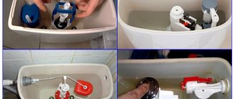
Sealing method
Since the pipeline fittings contain moving parts, and the system operates under conditions of elevated pressures and temperatures, a device is needed that will limit the working environment from the environment.
For this we use:
- stuffing box;
- membrane;
- bellows;
- hose.
Rice.
11 Types of sealing Figure 11 shows the gland and bellows method of sealing fittings.
The oil seal device consists of a special chamber through which the moving part (spindles or rod) passes. To prevent the release of the working medium, a groove is provided in the stuffing box for laying the seal. The latter is used:
- asbestos;
- paronitis;
- thermally expanded graphite.
For a specific area of operation of the valve, the packing is additionally reinforced and impregnated. For example, paronite has 4 versions, shown in Table 2.
table 2
Thermally expanded graphite (or TEG for short) also has several modifications.
TRG is used as a reinforcing agent:
- stainless steel wire;
- cotton thread;
- fiberglass;
- lavsan;
- Inconel wire.
The bellows is a long metal corrugated tube into which the stem fits. The corrugation withstands significant mechanical, temperature impacts and bending. Basically, bellows are used in cryogenic fittings.
The membrane is used at low pressure and temperature of the environment. Some types of fittings have a valve that simultaneously acts as a membrane.
In the hose fittings (Fig. 9), the system is sealed due to the presence of a rubber hose in the passage hole. No additional devices are needed here.
Nominal, working and test pressure
In all regulatory documents it is designated PN and measured in MPa (mega Pascals). On the websites of Russian manufacturers of pipeline fittings, they are most often designated Ru with the unit of measurement in atm.
MPa corresponds to atm. So:
1 MPa = 10 atm.
The nominal pressure is the maximum pressure at which normal operation of the valve is possible at a temperature of the transported substance of 200C. In this mode, the body parts are not subject to deformation, and the device itself is guaranteed to serve its full service life.
PN reflects the highest pressure at a substance temperature of only 200C. This means that at higher temperatures, the maximum pressure decreases.
The relationship between maximum pressure and temperature can be seen in the table below.
Table 3 Dependence of temperature on pressure
Working pressure is the maximum pressure in the pipe at a given temperature.