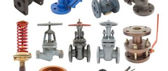
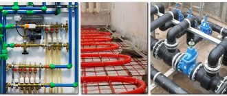
A gas pipeline is an engineering structure, each element and node of which solves an important specific functional task and is responsible for the safety, quality and uninterrupted functioning of the network. A variety of gas fittings and equipment vary in complexity of design, material of manufacture, purpose and type.
Fittings for gas pipelines are a broad class of fixtures and devices that are mounted on gas pipelines, as well as on devices. With their help, switching off/on, changing the direction, quantity, pressure of the gas flow or completely removing gases are carried out. A wide range of these parts are classified, thanks to which you can quite easily understand the issue of classifying gas fittings.
Let's look together at the variety of fittings for gas pipelines and the features of their selection.
Classification of gas fittings.
Based on their purpose, existing types of gas fittings are divided into:
- on shut-off valves - for periodic sealed shutdowns of individual sections of the gas pipeline, equipment and devices;
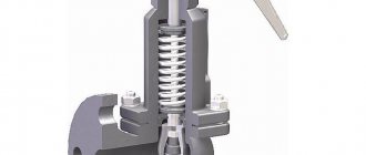
- safety valves - to prevent the possibility of gas pressure increasing above the established limits;
- reverse-acting fittings - to prevent gas movement in the opposite direction;
- emergency and shut-off valves - to automatically stop the flow of gas to the emergency area in case of violation of the specified regime.
When choosing gas equipment and fittings, you must be guided by the current GOST and SP.
Valuable information is contained in the materials of the research center for industrial gas equipment “Gazovik” (NIC PGO “Gazovik”), which collects, analyzes, and verifies the reliability of information about the degree of quality, reliability, competitiveness and safety of industrial gas equipment products.
All fittings used in the gas industry are standardized. According to the accepted symbol, the code for each fitting product consists of four parts. In the first place is a number indicating the type of reinforcement (table below).
Valves classification
Gas disk products are most widely used in the construction of gas pipelines. They can be roughly divided into two categories: with a closed and retractable spindle.
- The first category of valves is characterized by stationary fixation of the spindle on the lid using a protrusion that does not allow any movement in the vertical direction. The protrusion moves into a recess on the upper wedge, which in turn moves along a vertical line as the spindle turns.
At the bottom of the product there is a second wedge, which is equipped with locking discs. When the spindle is turned, the wedges of the second element are lowered until they reach the bottom of the pipeline. At the same time, the upper wedge closes the discs, closing the gas passage.
- with a shaft extending beyond the body, made of cast iron or metal. The spindle movements are aimed at moving the flywheel and threaded nut.
At the end of the shaft there are two disks with a spacer wedge fixed between them. When turning, the flywheel moves the spindle in a downward direction, due to which the disks are pushed apart by the wedge and the gas flow is blocked. Rotation in the opposite direction resumes the movement of the gas flow.
For tightness, the product is supplemented with a sealing gland, which guarantees an absolute stop of gas.
Symbols for the type of reinforcement
| Type of fittings | Type designation | Type of fittings | Type designation |
| Pipe valves | 11 | Rotary check valves | 19 |
| Shut-off valves | 14 and 15 | Valves regulating | 25 |
| Lift check valves | 16 | Gate valves | 30,31 |
| Valves safety | 17 | Gates | 32 |
On the second - the symbol of the material from which the valve body is made (table below).
Features of choosing fittings and equipment
When choosing fittings for gas pipelines, you should pay particular attention to the chemical and physical properties of the material from which it is made.
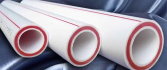
The most popular materials for the manufacture of gas fittings are cast iron and steel. This is due to the requirements for an increased level of strength and reliability. Polymer elements, which are excellent for water pipelines, are not applicable here; in addition, they can be easily damaged.
Steel is the most popular material for the manufacture of gas fittings. Such equipment is affordable and highly durable.
Experts do not recommend using equipment with bronze sealing inserts on gas pipelines. This is due to the fact that LPG contains hydrogen sulfide, which can have a negative effect on bronze and copper alloys.
Symbols for valve body materials
| Housing material | Designation material | Housing material | Designation material |
| Carbon steel | With | Brass and bronze | b |
| Acid-resistant and stainless steel | nz | Viniplast | VP |
| Gray cast iron | h | Alloy steel | PM |
| Malleable cast iron | CC | Aluminum | A |
The third is the serial number of the product. On the fourth - symbol of the material of the sealing rings: b - bronze or brass; nzh - stainless steel; r - rubber; e - ebonite; BT - babbitt; bk - there are no special sealing rings in the body and on the shutter.
For example, the designation of the PbYubk crane is deciphered as follows:
11 - type of fittings (faucet), b - body material (brass), 10 - serial number of the product, bk - type of seal (without rings).
Most types of valves consist of a shut-off or throttling device. These devices are a housing closed with a lid, inside which the shutter moves.
Moving the valve inside the housing relative to its seats changes the area of the hole for gas passage, which is accompanied by a change in hydraulic resistance.
In shut-off devices, the surfaces of the valve and seat that come into contact when parts of the gas pipeline are disconnected are called sealing surfaces. In throttling devices, the valve and seat surfaces that form a controlled passage for gas are called throttling surfaces.
Main characteristics of gas valves of shut-off type
Gas valves of the shut-off type in the form of valves are the most popular technical element of gas systems. They are used in gas pipelines with DN = 50–2000 mm and Pр = 0.1–20.0 MPa. Valves perform the functional task of shutting off the gas flow. In their designs, the shut-off device moves perpendicular to the direction of the axis of the gas pipeline pipes.
Wedge valves may not have a solid valve, but a hinged valve consisting of 2 disks. In parallel valves, the gate also has a pair of discs and a spacer wedge between them.
Advantages of valves over other gas shut-off valves
The presence of a valve allows gas to be supplied not only in the forward direction, but also in the reverse direction. The rotation of the gas flow is excluded. In the open position, this extremely easy-to-maintain shut-off device creates minimal resistance to gas flow.
Taps, valves and dampers
Shut-off valves in the form of ball, cone and cylindrical taps and valves not only allow you to quickly turn off a gas appliance or a section of a gas supply pipeline, but can also help regulate the flow of gas transported through the pipeline.
The advantages of taps and valves with ball and other shaped valves are their multi-purpose purpose, ensuring full passage of the gas environment and compactness.
Dampers can solve the functional task of shutting off and regulating gas flow. The design of the commercially produced device, in addition to the steel (cast iron) body and locking disk body, contains a drive shaft and seals. The advantages of dampers include:
- wide temperature range and gas pressure range;
- structural simplicity;
- low weight and metal consumption;
- low cost, etc.
The advantages are more pronounced in conditions of large Du.
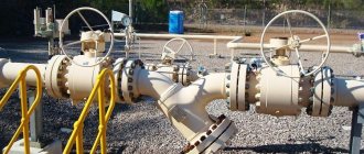
Buy gas shut-off valves. How to choose the right equipment for gas pipeline networks
Selecting equipment for gas pipeline networks has its own difficulties. Many factors must be taken into account, including the degree of aggressive action of the gas on the material from which the fittings are made. Natural gas does not have a noticeable corrosive effect on steel and cast iron structural elements. Cast iron is less durable than steel. For this reason, cast iron shut-off and control elements should not be used in pipelines with a working fluid pressure of more than 1.6 MPa.
Hydrogen sulfide in natural gases has a negative effect on copper alloys. There is an opinion: for this reason, you should not use some elements, including O-rings that are made of bronze. It would be better to use similar parts made of stainless steel. In this case, the reinforcing devices will be distinguished by significant reliability and long service life.
In this regard, it should be noted that the level of hydrogen sulfide in natural gas is insignificant. According to the standards, it is 2 g/per 100 cubic meters. m. Such a concentration cannot have a significant corrosive effect on parts made of bronze and other copper alloys. In addition, the surfaces of the valve and seat, which are made of a non-ferrous alloy, corrode less than those made of ferrous metal.
Gas shut-off valves are one of the most significant elements of engineering heating systems, as they are the key to their safe operation. As a rule, the shut-off valves used in various gas heating systems are subject to increased safety requirements. In this regard, it is necessary to pay special attention to the quality of such products. Shut-off valves for gas pipelines are used to shut off gas flows at certain phases of operation of heating equipment. Valves, gate valves, valves, taps and closures are all types of gas shut-off valves. To order shut-off valves from us, you will only need to spend a few minutes of your time. The online store allows you to purchase shut-off valves online, which saves you the effort and time of visiting a regular store. If you decide to buy gas shut-off valves from us, you can rest assured of its highest quality, because we offer products from leading manufacturers that are guaranteed to have high reliability. Affordable prices, detailed descriptions and characteristics, customer reviews - all this will allow you to purchase a product that is optimal in terms of price and quality.
Shut-off valves.
Shut-off valves include various devices designed to hermetically shut off individual sections of a gas pipeline. They must ensure tight shutdown, quick opening and closing, ease of maintenance and low hydraulic resistance.
Gate valves, taps, and valves are used as shut-off valves on gas pipelines.
The most common type of shut-off valves is valves (figure below), in which gas flow or its complete cessation is controlled by changing the position of the valve along the sealing surfaces. This is achieved by rotating the flywheel. The spindle can be retractable or non-retractable. When the flywheel rotates, the non-retractable spindle moves around its axis along with the flywheel. Depending on which direction the flywheel rotates, the threaded gate bushing moves along the threads on the bottom of the spindle down or up and lowers or raises the gate valve accordingly. Rising stem valves move the spindle and associated valve by rotating a threaded bushing mounted in the center of the handwheel.
For gas pipelines with a pressure of up to 0.6 MPa, valves made of gray cast iron are used, and for gas pipelines with a pressure of more than 0.6 MPa, valves are made of steel.
Gate valves can be parallel or wedge. In parallel valves, the sealing surfaces are located parallel, with a spacer wedge between them.
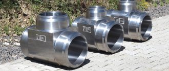
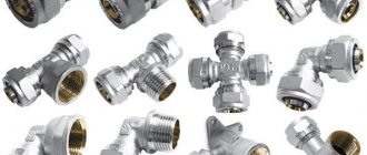
Connecting fittings for gas pipelines
During the installation of a gas pipeline, it may be necessary to connect pipes of different materials or different diameters. In this case, a connecting flange element is built into the network - auxiliary joining parts.
This category of fittings includes flange adapters, clamps, plugs, couplings, bends, crosses, tees, in short, parts whose design does not provide for a locking and control mechanism.
Connecting fittings will be required if there is a need to connect pipes made of different materials, sections of pipelines of different diameters, as well as when turning and branching
Tees and bends are used to branch the gas pipeline. They are installed in cases where the pipe reaches the distribution section for a populated area, but this point is not the final point.
With the help of control valves, the pipeline is divided and part of the transported gas goes to the populated area, and part is transported further.
Steel tees are made from various grades of steel. They can be used in almost any work environment. They provide high-quality pipe connections and have good tightness
Valves
a - parallel with a retractable spindle: 1 - body; 2- locking discs; 3 - wedge; 4 - spindle; 5 - flywheel; 6 — stuffing box; 7 - sealing surfaces of the body; b - wedge with non-retractable spindle: 1 - wedge; 2- cover; 3 - bushing; 4 - nut; J - flywheel; 6 — oil seal; 7 - collar; 8 - spindle
When closing the valve, the wedge rests on the bottom of the valve and pushes the disks apart, which create the necessary density with their sealing surfaces. In wedge valves, the side surfaces of the valve are not parallel, but oblique. Moreover, these valves can be with a solid shutter or a shutter consisting of two disks. It is advisable to install parallel valves on underground gas pipelines.
However, valves do not always provide a sealed shutdown, since the sealing surfaces and bottom of the valve often become dirty. In addition, when operating valves with the shutter not fully open, the discs wear out and become unusable.
All repaired and newly installed valves must be checked for tightness with kerosene. To do this, the valve should be installed in a horizontal position and kerosene should be poured on top; on the other side, the valve should be painted with chalk. If the valve is tight, there will be no kerosene stains on the valve.
On underground gas pipelines, valves are installed in special wells (figure below) made of precast reinforced concrete or red brick. The well cover must be removable for ease of disassembly during repair work.
Characteristics of valves
The diameter of the passage hole in the valves is the same as the cross-section of the pipeline. Such elements are called full bore; they can be controlled in two ways. Most often, manual control is used (using a steering wheel); in addition, a special drive can be used to control the valve. They produce products with hydraulic or electric drives; occasionally you can find controls that use a pneumatic drive.
Motorized valves are much easier to operate. If the device has a large cross-section and is manually operated, then the forces required to close or open the pipeline can be very large (often observed when valves are rarely inspected and maintained).
The locking element device can also be of several types:
- Gate;
- Hose;
- Parallel;
- Wedges.
Let's take a closer look at the wedge locking part of the valve.
Construction of gas wells
a - installation of a valve in a well: 1 - case; 2 - valve; 3 - carpet; 4 — hatch; 5 — lens compensator; 6 - gas pipeline; b - construction of a small-sized well: 1 - outlet; 2 - tap; 3 - gasket; 4 - well wall
The wells have hatches that can be easily opened for inspection and repair work. On the roadway, hatches are installed at the level of the road surface, and on unpaved driveways - 5 cm above ground level with a blind area of 1 m in diameter around the hatches. Where possible, it is recommended to move the valve control under the carpet.
Where gas pipelines cross the walls of the well, cases are installed, which are sealed with bitumen for density. Wells must be waterproof. An effective remedy against the penetration of groundwater is waterproofing the walls of wells. In case of water penetration, special pits are installed in the wells to collect and remove it.
On gas pipelines with a diameter of up to 100 mm, when transporting dried gas, small-sized wells are installed (figure above) with fittings installed in the upper part, which ensures servicing of the fittings from the surface of the ground. In such wells, taps are installed instead of valves.
In forced lubrication valves (figure below), sealing is achieved by introducing a special grease under pressure between the sealing surfaces. The lubricant tucked into the hollow channel of the upper part of the plug is pumped through the channels into the gap between the body and the plug by screwing the bolt. The plug rises slightly upward, increasing the gap and ensuring ease of rotation; the ball valve and brass gasket prevent the grease from being squeezed out and gas from penetrating out.
How is a gas valve made?
The valve can be configured in several ways. Let us consider in detail the device of each type.
- gate Designed to block a moving stream. Valves are installed by breaking the main pipeline and installing flange connections at the break point;
- hose Gas is supplied using an elastic hose. A rod is used to block the flow of the medium. All parts are made of metal and isolated from the working gas movement with a short hose;
- parallel. The design is made using two disks. The manufacturing material for the part is cast iron or steel. The rod element can be used retractable or non-retractable. The metal-to-metal seal between the shell and the discs allows for complete shut-off of fluid movement;
- wedge Manufactured for full bore gas mode with a non-retractable element. The wedge can be used in three versions: rigid, composite or elastic. The latter allows the flow to be blocked by deforming the corner.
The gas flow is stopped by a metal-to-metal or rubber-to-metal seal. The valve is connected to the main line using screwed threads or couplings.
Advantages of a wedge gate valve
- A hard wedge completely blocks the gas pipeline. To achieve absolute tightness, it is necessary to precisely adjust the blade to achieve an angle similar to the angle between the holes.
- Seals in a rigid wedge design have a fairly long service life.
- No great effort is required to block the flow.
Cast iron valve with pressure lubrication
1 - channels; 2 - base of the plug; 3 - bolt; 4 - ball valve; 5 - gasket
In addition to lubricated valves, simple rotary valves are used, which are divided into tension, gland and self-sealing valves. These valves are installed on above-ground and on-site gas pipelines and auxiliary lines (pulse and purge gas pipelines, condensate collector heads, inlets).
In tension taps, mutual compression of the sealing surfaces of the plug and the body is achieved by screwing the tension nut onto the threaded end of the plug, equipped with a washer.
To create tension in the plug, the end of its conical part should not reach the washer by 2-3 mm, and the lower part of the inner surface of the body should have a cylindrical groove. This makes it possible, as the valve plug wears out, to lower it lower, tightening the shank nut, and thereby ensure tightness.
Benefits and disadvantages of use
Pipeline valves continue to be used due to the following beneficial qualities:
- Simple and reliable design. The operating principle and main parts have remained unchanged for more than one and a half years, which indicates the reliability of the structural components.
Valves on a gas pipeline Source erkindik.media
- Ease of use. The valve allows you to shut off a pipeline of any diameter with relatively little effort. For example, with a diameter of 100 mm, a plug valve is very difficult to turn, a ball valve is easier, but only for a strong person. Even a child can open and close a well-lubricated and maintained valve.
- Improved performance characteristics. The devices are designed to operate under a wide range of temperatures and pressures. Some varieties are designed to work under the influence of an aggressive transmitted environment.
- Reliability of operation. The designs of all types of valves are characterized by high tightness. They are selected in accordance with the internal diameter of the pipeline, so the hydraulic parameters of the transported medium are not violated. The movement of the damper is smooth, so the flow speed also changes smoothly, and water hammer does not occur.
- Easy maintenance, maintainability. Using nuts or bolts to assemble the fixture makes it easier to install and repair. A worn valve can be easily replaced with a new one.
Design of a disc valve Source autogear.ru
Condensate collectors
a - high pressure; b - low pressure; 1 - casing; 2 - inner tube; 3 - contact; 4 - lock nut; 5 - tap; 6 - carpet; 7 - plug; 8 — reinforced concrete cushion under the carpet; 9 — grounding electrode; 10 — condensate collector body; 11 - gas pipeline; 12 — gasket; 13 - coupling; 14 - riser
Depending on the humidity of the transported gas, condensate collectors can have a larger capacity for wet gas and a smaller capacity for dry gas. Depending on the gas pressure, they are divided into condensate collectors of low, medium and high pressure.
A low-pressure condensate collector is a container equipped with an inch tube, which runs under the carpet and ends with a coupling and plug. Condensate is removed through the tube, the gas pipeline is purged and the gas pressure is measured.
Medium and high pressure condensate collectors are somewhat different in design from low pressure condensate collectors. They have an additional protective tube, as well as a valve on the internal riser. The hole in the upper part of the riser serves to equalize the gas pressure in the riser and the case. If there were no hole, condensate under gas pressure would constantly fill the riser. At low temperatures, condensate may freeze and risers may rupture.
Under the influence of gas pressure, condensate is automatically pumped out. When the tap is closed, the gas acts against the condensate, which falls down under the influence of its mass. When the tap is opened, the resistance stops and the condensate comes to the surface.
Various classification
Depending on the composition of the working environment, there is the following classification of fittings:
- Energy;
- Cryogenic;
- Steam-water;
- Oil;
- Ventilation.
Energy fittings
Energy is used at high parameters of water and steam. In most cases, energy fittings refer to steam-water fittings, which operate at high pressures and temperatures. Energy fittings are necessary for transporting oil and gas.
Cryogenic fittings are used for work in special conditions where the working environment is at low temperatures. Cryogenic medium is helium, hydrogen, fluorine, oxygen, which are used in liquid and gaseous form with temperatures up to minus 260˚С. Therefore, cryogenic reinforcement must have ultra-strong impact strength. A pipeline with a cryogenic medium must have insulated shut-off valves, which reduces heat inflow and reduces evaporation of the medium.
Classification of devices by area of application:
- Industrial;
- Special;
- Ship;
- Plumbing.
According to the control method, the classification distinguishes between controlled and automatic devices. The classification according to the method of connection to the pipeline is as follows:
- Flange connections;
- Coupling;
- Fittings.
- Welded.
Cryogenic fittings
Compensators.
During the operation of gas pipelines, the temperature change can reach several degrees, which causes stresses of several tens of MPa. Therefore, to prevent the destruction of the gas pipeline from temperature influences, it is necessary to ensure its free movement. Devices that ensure the free movement of pipes are compensators - lens, lyre-shaped and U-shaped. On underground gas pipelines, lens compensators are most widespread (figure below).
Types of shutters
Types of pipeline valves can be classified in different ways; The easiest way is to rely on differences in the configuration of the locking unit. The classic option in the post-Soviet space is the wedge valve. Another name for the mechanism is a parallel (double-disk) valve with the following device:
- There is a rod (spindle) located vertically, which is driven by rotation of the steering wheel.
- At the bottom of the rod there is a paired shut-off element (cheeks, plates) that shuts off the water. The cheeks are made of cast iron and have a round shape, and are equipped with brass mirrors along the edge. The same mirrors are located in the housing.
- When we lower the rod (to block the movement of fluid), the wedge located in the lower part of the body rests against the rod, pushes the cheeks apart, and they are pressed tightly against the mirrors in the body.
- The tightness of the valve is ensured only by tightly rubbing the metal mirrors on the cheeks to the mirrors on the body.
Sectional view of a wedge valve Source santehkomplekt.ua
Lens compensator
1 - pipe; 2 - flange; 3 - shirt; 4 - half lens; 5 - rib; 6 - paw; 7 - nut; 8 - thrust
Lens compensators are made by welding from stamped half-lenses. To reduce hydraulic resistance and prevent clogging inside the compensator, install
a guide pipe welded to the inner surface of the compensator on the gas inlet side. The lower part of the lenses through the holes in the guide pipe is filled with bitumen to prevent the accumulation and freezing of water in them.
When installing the compensator in winter, it is necessary to stretch it a little, and in summer, compress it with tie rods. After installation, the rods must be removed. Compensators, when installed next to valves or other devices, provide the ability to freely dismantle flange fittings and replace gaskets (figure below).
Options for connecting valves, other valve-type devices and gas appliances
When installing a pipeline network, you can use a coupling, pin, flange, welded, fitting, clamp or nipple connection.
Flange is used to solve the problem of connecting a valve or other fitting device to a pipeline or tank provided DN>50 mm. This type of connection can be used over a wide range of pressures and passages, and is one of the most reliable. Its advantages are significant strength and the ability to repeatedly install and dismantle the structure without loss of quality. There are also disadvantages, which include heavy weight and loosening of tightness leading to leakage during long-term operation, which requires correcting the problem during maintenance.
Couplings can connect equipment with DN=<65 mm. The couplings used for connection have internal threads. A hex wrench is required for installation.
The pin type, unlike the coupling type, has an external thread.
Using welding, a permanent connection of high reliability and guaranteed tightness is obtained. Due to the disadvantage manifested in the complexity of replacing and repairing fittings, the method is used less often than others.
In the nipple version, the connection of certain fittings to a tank or pipeline is carried out using a nipple, in the fitting version - a fitting.
In the compression fitting, the pipes are tightened to the pipeline flanges using studs and nuts.
Installation of expansion joints
a - lens with a valve; b - rubber-fabric; 1 - lower casing; 2 - upper casing; 3 - pin; 4 - coupling; 5 - nozzle; 6 — cap; 7 - small carpet; 8 — pillow under the carpet; 9 — reinforced water and gas pipe; 10 — welded flange; 11 - valve; 12, 14 — gaskets; 13 — two-lens compensator
Due to the fact that there is very often water in the wells, the nuts and coupling bolts rust, so working with them becomes difficult, and in some cases, operating personnel leave the coupling bolts on the lens compensators without removing the nuts. The lens compensator ceases to perform its function, so new compensator designs do not provide tie bolts. During repairs, a clamp is used to compress expansion joints.
Due to the fact that the expansion joints are made of thin-walled steel with a thickness of 3-5 mm, they cannot be of equal strength to the pipe. Limited pressure is the main disadvantage of lens compensators. To increase the permissible pressure, expansion joints are made of stronger steel, with more waves, but less height.
There are expansion joints made of bent, usually seamless pipes (U-shaped and lyre-shaped). The main disadvantage of such compensators is their large dimensions. This limits their use on large diameter pipelines. In gas supply practice, bent expansion joints are not widespread and are not used at all as installation expansion joints when installing valves.
Rubber-fabric compensators have great advantages (figure above). They are able to perceive deformations not only in the longitudinal, but also in the transverse directions. This allows them to be used for gas pipelines laid in mining areas and in earthquake-prone areas.
What does the valve consist of?
By definition, it is clear that the functional direction of a gas valve is to shut off a moving medium. Closing occurs thanks to a flat valve mounted on a threaded valve stem. The shutter, when moving perpendicular to the flow of the medium, completely blocks the movement.
The valve is made of:
- locking element wedge, gate, one or two disks;
- housings made of cast iron or steel. Brass is also used;
- covers made of similar materials;
- threaded rod or spindle. More often steel is used for its production;
- flywheel, drive.
Construction and installation of internal gas pipeline systems
In low-pressure gas pipelines, when supplying household consumers with artificial gas, the pressure should be up to 0.002 MPa (0.02 kgf/cm2), when supplying natural gas - up to 0.003 MPa (0.03 kgf/cm2) and with liquefied gas - up to 0.004 MPa (0 .04 kgf/cm2).In gas pipelines laid indoors at consumers, the following pressures are allowed:
1) at industrial enterprises, in separately located boiler houses, municipal and agricultural enterprises - 0.6 MPa (6 kgf/cm2);
2) at agricultural and municipal enterprises (baths, laundries, dry cleaning factories, bakeries, etc.) built into buildings - 0.3 MPa (3 kgf/cm2);
3) in residential and public buildings, public catering establishments (restaurants, canteens, buffets, etc.), as well as in heating boiler houses built into buildings and consumer service enterprises (laundries, hairdressers, studios, etc.) - low pressure (up to 0.005 MPa).
The nominal gas pressure in front of household gas appliances is taken as follows:
1) natural pure gas and oil and gas fields
mixtures of liquefied hydrocarbon gases with air and other gases with
Lower calorific value 33.6–42 MJ/m3 (8000–10,000 kcal/m3) —
2 kPa (200 mm water column), and for populated areas with already folded
current gas supply systems, nominal pressure 1.3 kPa
(130 mm water column);
2) artificial and mixed gases with a lower calorific value of 14.7-18.9 MJ/m3 (3500-4500 kcal/m3) -1.3 kPa (130 mm water column);
3) liquefied hydrocarbon gases with a lower calorific value of 92.4-117.6 MJ/m3 (22,000-28,000 kcal/m3) - 3 kPa (300 mm water column).
Materials used for gas pipelines and gas appliances.
Gas pipelines made of steel pipes are laid indoors; seamless, straight-seam welded, spiral-seam, water-gas pipes, etc., the welds of which are equal in strength to the base metal of the pipe. Pipes are usually connected by welding. Threaded and flanged connections are provided only in places where shut-off valves, gas appliances, instrumentation, etc. are installed. Detachable connections of gas pipelines must be accessible for inspection and repair. Connecting parts and gas pipeline parts made of ductile cast iron or mild steel (cast, forged, stamped, bent or welded) are used.
When making bent bends or bent sections of gas pipelines from water and gas pipes, the bending radius should be at least 2.5 DR for pipes with a diameter of up to 40 mm inclusive and 3.5 D for pipes with a diameter of 40-50 mm inclusive. Pipes with a diameter of more than 50 mm are not used for these purposes.
To seal threaded connections, use strands of flax coated with red lead or lead white, fluoroplastic material (FUM) in the form of tape and cord, as well as other sealants that ensure the tightness of the connections. Gaskets for flange connections are made of paronite. To connect pipes for welding, the type and brand of electrodes, welding wire and fluxes are selected depending on the grade of steel being welded. For manual electric arc welding of steel pipes and products, thickly coated electrodes E42, E46, E50A, E42A and E46A are used. For automatic and semi-automatic submerged arc welding, welding wire of the Sv-08-A grade is used, for pipes made of low-carbon steels and grade Sv-08-GA for pipes of low-alloy steels. When welding pipes in a gaseous carbon dioxide (carbon dioxide) environment, welding wire of the Sv-08G2S grade is used; for gas welding, welding wire of the Sv-08A and Sv-08GA grades is used.
Gas pipelines are equipped with valves, taps, and gate valves designed for gas environments. Rotary valves and gate valves must have 90° rotation limiters, and valves with a non-rising spindle must have opening degree indicators. Valves from £>y to 80 mm must have a mark indicating the direction of gas passage in the plug. The valve seals are stuffed with asbestos cord impregnated with graphite mixed with mineral oil.
Household gas stoves must comply with the requirements of GOST 10798-77 and technical specifications approved in the prescribed manner. To measure gas flow, volumetric meters and flow meters, orifice devices with differential pressure gauges are used. Differential pressure gauges are supplied complete with restriction devices - diaphragms or nozzles.
Domestic water heaters must have automatic devices that ensure the burners turn off when the gas supply stops, the flame goes out and there is no required vacuum in the chimney.
Gas air heaters and convectors for heating buildings must be equipped with automatic control and safety devices that ensure the maintenance of a given temperature in the room or supply air, as well as turning off the gas supply to the burners in the event of an unacceptable change in gas pressure or a decrease in draft below the minimum permissible, when the flame goes out and stopping the fan supplying air.
Installation work. Before starting the installation of internal gas supply systems, the following must be prepared:
1) interfloor ceilings, walls and partitions on which gas equipment and appliances will be installed and gas pipelines and fittings will be installed;
2) holes for laying gas pipelines in foundations, ceilings, walls and partitions,
3) channels and grooves for gas pipelines;
4) clean floors or foundations for gas equipment and appliances;
5) plastering walls in kitchens and bathrooms where gas equipment is installed;
6) cladding of walls near which gas equipment and appliances will be installed and gas pipelines installed;
7) painting floors in places where gas equipment and appliances are installed;
 bathtubs, sinks, sinks, washbasins or other appliances to which pipelines are connected.
When installing internal gas pipelines, the pipes are connected by welding. Threaded and flange connections are used in places where disconnecting devices, compensators, pressure regulators, instrumentation and other fittings are installed, as well as in places where gas appliances and burners are connected to the gas pipeline. At the points of connection with fittings or fittings, gas pipelines should not have distortions.
Welded and threaded connections of gas pipelines and fittings are not allowed to be embedded in walls or ceilings. Sections of gas pipelines laid in casings should not have butt joints. They must be painted during installation. The distance from the weld to the casing (when the gas pipeline passes through a wall or foundation) is taken to be at least 100 mm.
Sections of workshop gas pipelines laid in channels with removable ceilings must have a minimum number of welded joints. Threaded and flanged connections are not permitted in these areas.
The location of the supports, the distances between them and the methods of fastening the gas pipeline should be taken in accordance with the project. Gas pipelines must lie tightly on the supports, without gaps. When marking the location of supports, it is necessary to take into account the need to fasten the gas pipeline in places where shut-off valves are installed, turns, branches and in places where columns, pilasters, air ducts, etc. are bypassed.
Valves on vertical and horizontal gas pipelines should be placed so that the axis of the valve plug is parallel to the wall; It is prohibited to install the faucet with the stop nut towards the wall.
Gas pipeline risers are installed strictly vertically; Deviation from the vertical is allowed no more than 2 mm per 1 m of gas pipeline length.
For ease of assembly and disassembly of pipes, it is necessary to provide for connections next to shut-off valves installed on branches from risers or on boats to gas appliances (counting along the gas flow), as well as at the junctions of individual gas pipeline units.
When installing a valve with a drive (mechanical, electric or hydraulic), the spindles must be positioned as indicated in the manufacturer's data sheets. Manually operated valves can be installed in any position, except for free-hanging valves, which must be positioned with the spindle up only.
The distance from the wall to the gas pipeline being laid is indicated by the project; in the absence of such instructions, the distance between the gas pipeline and the wall must be equal to at least the radius of the pipe.
Before installation on site, shut-off valves must be subject to revision: reconservation of lubrication, inspection of seals and gaskets, and leak testing in accordance with the requirements of state product standards. When installing general-purpose fittings (not intended for gas) on gas pipelines, it must also be tested for strength and density of the material.
Gas pipelines inside buildings are laid openly. Gas pipeline entries into residential buildings are located in non-residential premises accessible for inspection of gas pipelines (staircases, kitchens, corridors, etc.).
The introduction of low-pressure gas pipelines into technical undergrounds and technical corridors and their laying through these premises in residential and public buildings is permitted only when external gas pipelines are connected to these buildings in intra-block collectors in accordance with the requirements of the instructions for the design of intra-block utilities in collectors and technical corridors.
The entry of gas pipelines into public buildings, buildings of public catering establishments and public utility facilities is arranged in staircases or in rooms where gas appliances are installed.
Entrances to the workshops of industrial buildings and utility enterprises are arranged directly in the premises where the equipment consuming gas is located, or in an adjacent room connected by an open doorway.
The minimum distance (from the surface of the pipe) between gas pipelines, electrical equipment and utilities indoors is taken as follows:
1) with open wiring of insulated wires or electric cables when laid in parallel - 250, and when crossing - 100 mm;
2) for hidden electrical wiring or installation in a pipe (from the edge of a sealed furrow or pipe)—50, and when crossing—10 mm;
3) from current-carrying parts of open (bare) electrical wires with voltages up to 1000 V - 1000 mm;
4) from distribution and switching electrical panels or cabinets - 300 mm (crossing is not allowed);
5) when laying utilities (water supply, sewerage and other pipelines) at intersection - 20 mm, and when laying parallel, the distance to them is taken locally, ensuring the possibility of installation, safe operation and repair of pipes.
In residential and public buildings, lighting wires can be crossed without a gap, provided that the electrical wires are enclosed in an ebonite or rubber tube protruding 10 cm from each side of the gas pipeline.
The distance from plug sockets, switches, electric bells and other elements of the electrical network is taken in accordance with the rules of the PUE approved by the USSR Ministry of Energy.
Transit laying of low and medium pressure gas pipelines through a room where gas is not consumed is permitted, provided that there are no fittings on the gas pipeline and unhindered 24-hour access to the premises is provided for personnel servicing the gas pipeline. These requirements do not apply to gas pipelines laid in staircases, vestibules, and corridors of residential and public buildings. When reconstructing residential buildings, transit laying of gas pipelines through living rooms is allowed if no other laying is possible. In this case, the gas pipeline within residential premises should not have threaded connections and fittings.
Gas instantaneous water heaters are installed on fireproof walls of premises at a distance of at least 20 mm from the wall, and on fire-resistant walls - at a distance of at least 30 mm. In this case, the wall surface must be insulated with roofing steel over asbestos sheets 3 mm thick. The insulated area should protrude 100 mm beyond the dimensions of the water heater. When covering a wall with glazed tiles, insulation is not provided.
Unplastered wooden walls in kitchens are insulated with plaster, asbestos plywood or roofing steel over asbestos 3 mm thick. Asbestos can be replaced with felt, at least 15 mm thick, impregnated with clay mortar. When installing a stationary gas stove, the wall insulation should start from the floor. The distance between the back wall of the slab body and the plastered wall is taken to be at least 70 mm.
Gas small-capacity boilers and capacitive water heaters are located near fireproof walls at a distance of at least 15Q mm from the wall, and when placed near fire-resistant walls, the wall must be insulated with roofing steel on an asbestos sheet 3 mm thick or asbestos plywood protruding 100 mm beyond the dimensions of the body. If the boiler is thermally insulated, then wall insulation is not required. When installing such boilers on a wooden floor, it is also insulated with roofing steel over a 3 mm thick asbestos sheet. The insulation must protrude 100 mm beyond the dimensions of the housing. When installing gas boilers, the same requirements must be observed.
Gas combustion products from household gas appliances, stoves. and Other gas equipment is diverted into the chimney from each appliance, stove or unit separately through roofing steel pipes with a diameter equal to the diameter of the smoke outlet pipe of the gas appliance with a slope towards the appliance. For gas boilers, a hole with a diameter of at least 50 mm is provided in the upper part of the chimney dampers. Explosion valves are installed on gas boiler units and on their hogs.
It is not allowed to install gas pipelines in basements, elevator rooms, ventilation chambers and shafts, warehouses of explosive industries and other premises to which access for maintenance personnel cannot be provided at any time of the day.
Low and medium pressure gas pipelines can be laid along the external walls of residential and public buildings of at least IV degree of fire resistance. Threaded and flanged connections on gas pipelines must not be placed under window openings and balconies of buildings. Low pressure gas pipelines Dy up to 50 mm can be laid along the external walls of wooden residential buildings (V degree of fire resistance). Hidden installation of gas pipelines, with the exception of liquefied gas pipelines, is used only in municipal and industrial enterprises in wall grooves covered with removable panels with holes for ventilation.
In industrial enterprises, boiler rooms, premises of consumer services and public catering enterprises, laboratories, gas pipelines to consumers can be laid in a concrete floor with anti-corrosion insulation and sealing of pipes with cement mortar. At the points where gas pipelines enter and exit from the floor, cases with a height of at least 3 cm are placed. Fittings cannot be installed on gas pipelines laid in a concrete floor, wall grooves and in channels with removable ceilings.
Gas pipelines for dry gas can be laid without a slope, and gas pipelines for wet gas with a slope from the meter of at least 0.003 by installing condensate collectors or fittings for draining condensate.
At the intersections of foundations, ceilings, landings, walls and partitions, gas pipelines are enclosed in cases made of steel pipes or other strong and durable materials. The space between the walls of the casing and the gas pipeline is sealed with tarred tow and bitumen. The end of the case should protrude 5 mm above the floor or platform, and when crossing walls and partitions, no protrusions are made. It is prohibited to lay gas pipelines through elevator shafts, ventilation ducts and chimneys.
If there are no gas meters and when only a gas stove is installed in the apartment, the gas supply pipeline to the stove can be located at the level of the connecting fitting, and the shut-off valve can be installed at a distance of at least 20 cm to the side of the stove. For overhead wiring, the crane is placed on the descent to the slab at a height of at least 1.5 m from the fireplace.
The method of hanging and fastening smoke exhaust connecting pipes must exclude the possibility of their deflection. The links of connecting pipes must be tightly pushed into one another along the gas flow by at least 0.5 of the pipe diameter. The connecting pipes must be tightly connected to the smoke duct. The end of the connecting pipe should not protrude beyond the inner wall of the channel; To do this, at the end of the pipe at a distance equal to the thickness of the channel wall, there must be a limiting device in the form of a corrugation or washer fixed to the pipe. The connecting pipes, made of black sheet steel, are coated with fire-resistant varnish after installation.
Infrared burners and other radiant heating devices should be checked by external inspection before being installed in place (before installation). The specified burners and devices that have damage to the ceramic tiles (cracks and potholes, sagging and contamination of the outlet openings of the ceramic tiles, dents in the housings) are not allowed to be used.
When installing gas burners on heating units, the following requirements must be met:
1) use burners that, in terms of their characteristics (type, performance, gas pressure in front of the burner, heat of combustion of gas) strictly correspond to those specified in the design;
2) inspect the burners outside and inside, and clean the gas and air outlets from possible blockages and blow them out with air;
3) securely fasten the burners;
4) when attaching burners to front plates, install an asbestos gasket between the front plate and the frame or lining (unit wall), as well as between the burner and the front plate to eliminate air leaks into the furnace of the unit;
5) when embedding the burner into the lining, seal the space between the burner and the lining with asbestos cord, and coat the firebox side with fireclay mortar;
6) there should be no distortions in the gas and air supply pipelines to the burners;
7) comply with the requirements for the installation of gas burners given in the drawings or in the factory installation and operating instructions.
Installation of control and automatic control devices must be carried out in strict accordance with the design instructions and factory instructions.
Instrumentation and measuring instruments should be placed in places convenient for servicing and monitoring their readings, where they will not be subject to shock. The devices are installed strictly vertically or horizontally and securely fastened. When connecting instrumentation and control devices to gas pipelines, you must comply with the requirements of SNiP.
Glass thermometers are installed in metal sleeves filled with oil and protected from damage from the outside with a case.
When laying straight sections of gas pipelines, curvature is allowed within 1 mm per 1 m of pipe. Branches are connected to the gas pipeline at right angles, unless there are other Instructions in the project. Gas pipelines laid in the floor groove to units installed in the middle of the premises of industrial and public utility enterprises are sealed after testing and covering them with anti-corrosion insulation specified in the project.
The installation of all purge or discharge pipelines is subject to the same requirements as the installation of main gas pipelines.
The installation of instrumentation impulse lines is carried out in accordance with the design instructions, also fulfilling the requirements of the installation and operating instructions of the device manufacturer. Impulse lines are connected to equipment, fittings and devices using union nuts. They are tested simultaneously with the main gas pipelines.
Measuring diaphragms and differential pressure gauges-flow meters must be installed according to the design, guided additionally by the rules for measuring the flow of liquids, gases and vapors with standard diaphragms and nozzles.
Before installation, rotary meters must be cleaned (rinsed) of preservative grease according to the instructions of the factory instructions. Rotary meters should be installed horizontally and level. Oil is poured into the gear and gearbox chamber after completion of all installation work. The meters are sealed in accordance with the instructions of the factory instructions.
When installing cylinder installations and gas pipelines to them, the following requirements must be observed:
1) cabinets or protective casings for cylinders must arrive at the site ready-made, painted, with warning notices applied to them;
2) if the piping of a cylinder installation (from cylinders to gas pressure regulators) is carried out at a procurement enterprise, then it must be tested for strength with water at a pressure of 2.5 MPa (25 kgf/cm2);
3) the gas pipeline extending from the external cylinder installation must have a horizontal section of at least 0.5 m in length to compensate for the movements of the installation in the event of settlement of its base. When connecting the reducer to a gas pipeline with a rubber-fabric sleeve longer than 0.35 m, a horizontal section of steel pipe is not required.
Rubber-fabric hoses used during the installation of individual cylinder installations must meet the requirements of the relevant GOSTs and SNiPs. When preparing hoses of the required length, fittings are simultaneously installed to ensure a reliable and hermetically sealed connection to the cylinder installation and the device; they are tested with a hydraulic pressure of 0.1 MPa (1 kgf/cm2). Sleeves that have deep scratches or other defects that affect strength must be replaced.
Gas pipelines made of rubber-fabric hoses, laid along walls and other structures of buildings and structures, are strengthened with the help of special brackets or clamps that prevent the hoses from being crushed. The distances between brackets (clamps) are taken within 50 cm.
Cylinders filled with liquefied gas are installed in place only after the installation of the cylinder installation is completed, and its acceptance into operation is carried out by representatives of the operating organization (trust, office, etc.).
When installing pipes, assembling components and installing equipment and devices, it is necessary to carry out operational control, checking compliance with the slopes of gas pipelines, the distances from gas pipelines to walls and to other pipelines, the verticality of risers, the distances between supports, as well as the serviceability of the fittings, the reliability of fastening of pipes and equipment, completeness of equipment, quality of threaded and welded connections.
Quality control of work should be carried out both during the manufacturing of components and blocks, and during the assembly of these components and installation of internal gas pipelines. When accepting products manufactured at the Central Plant. and transferred for installation, it is necessary to check the presence of stamps and markings on blocks, assemblies, as well as the availability of technical documentation and the completeness of all equipment and materials.
Acceptance of hidden work (laying a gas pipeline in a case through walls, floors, in furrows, cleaning the internal cavity of pipes, etc.) is carried out during the work process.
Testing and acceptance into operation. Installed gas pipelines are tested for strength and density by representatives of the construction and installation organization, and the density is necessarily tested in the presence of representatives of the customer and the gas utility with the corresponding entry in the construction passport of the facility.
When pneumatic testing of gas pipelines with pressure up to 0.01 MPa (0.1 kgf/cm2), liquid V-shaped pressure gauges filled with water are used for control. For test pressures above 0.01 MPa (0.1 kgf/cm2), mercury-filled V-shaped pressure gauges, reference pressure gauges or spring test pressure gauges can be used
When testing strength with pressure over 0.1 MPa (1 kgf/cmg), spring pressure gauges of class no lower than 1.5 (GOST 86215-77) are used, and when testing for density, standard and spring control pressure gauges or differential pressure gauges are used. Strength tests are carried out with the equipment turned off, if it is not designed for the test pressure. It is allowed to test the strength of individual sections of the gas pipeline.
The density of gas pipelines at the points where gas burners are connected to them is checked by representatives of the commissioning or operating organization by washing these places when igniting the equipment under the operating gas pressure.
When pneumatic testing of gas pipelines for strength, inspection and testing of connections using a soap emulsion is carried out to test for density.
In residential and public buildings and public utility facilities, low-pressure gas pipelines (when supplied with natural and liquefied gas) are tested with air:
a) for strength - with a pressure of 0.1 MPa (1 kgf/cm2) to identify defective areas in the area from the disconnecting device at the entrance to the building or staircase to the taps to the devices; the test is carried out before installing a meter on the gas pipeline (if it is not designed for test pressure), and the gas pipeline in the area allocated for the meter is connected with a jumper;
b) for density - a pressure of 4 kPa (400 mm water column) with connected gas appliances and an installed meter.
In the absence of meters, as well as when supplied with liquefied gas, the test is carried out at a pressure of 5 kPa (500 mm water column) with connected devices. The gas pipeline is considered to have passed the density test if the pressure drop in it within 5 minutes does not exceed 200 Pa (20 mm water column).
Density testing of internal gas pipelines is carried out after the air temperatures inside the gas pipeline and the environment have been equalized.
Internal low-pressure gas pipelines from individual and group cylinder installations of liquefied hydrocarbon gases in residential and public buildings are tested for strength and density according to the testing standards for natural gas pipelines.
Internal low-pressure gas pipelines in heating and industrial boiler rooms and premises of industrial and municipal enterprises in the area from the shut-off device at the gas pipeline entry into the building (or from the reducing unit located in the building) to the shut-off device at gas burners are tested for strength with air pressure of 0.1 MPa (1 kgf/cm2) to identify defective areas and for a density with a pressure of 10 kPa (1000 mm water column). The duration of the density test must be at least 1 hour; The pressure drop during this time is allowed to be no more than 600 Pa (60 mm water column).
Medium pressure gas pipelines up to 0.1 MPa (1 kgf/cm2) are tested with air for strength at a pressure of 0.2 MPa (2 kgf/cm2) and for density at a pressure of 0.1 MPa (1 kgf/cm2). The pressure drop over 1 hour during the density test should not exceed 1.5%.
Filling gas pipelines with water or aqueous solutions is not permitted.
Pipes, fittings and fittings with defects found on them during testing are replaced. Sealing or caulking of cracks, cavities and fistulas is strictly prohibited.
The system density test report is signed by representatives of the installation and operating organizations.
The installation organization presents the system installed and tested for strength and tightness to the acceptance committee consisting of representatives of the customer, the installation organization, the operating organization and Gosgortekhnadzor (for facilities that are subject to the safety regulations of Gosgortekhnadzor).
When accepting internal gas equipment, compliance with the design and SNiP requirements is checked:
a) work performed and materials and equipment used;
b) slopes of gas pipelines,
c) installation of gas pipelines, equipment and fittings.
as well as the strength of their fastenings;
d) completeness of gas appliances and equipment;
e) auxiliary devices (functionality and operation) in conjunction with
compliance with the project (smoke exhaust and ventilation outlets
devices, used electrical power and lighting equipment).
The release of gas into the gas network is carried out by the operating organization (Gorgaz, etc.) in the presence of a representative of the installation organization.
Acceptance of the gas supply system for operation is formalized by an act.
· How to choose a gas stove. What you need to know · Choosing a geyser. What you need to know · Gas boiler - the warmth of your home · Internal gas pipelines · Internal gas pipelines - SNiP 42-01-2002 GAS DISTRIBUTION SYSTEMS · Gas appliances · Operation of household gas equipment · Connection of gas pipelines. Insertion into a gas pipe · Instruments for measuring gas contamination and gas leaks · Classification of gas pipelines · Gas supply. Construction of a gas pipeline · Operation of electrical protection means for underground gas pipelines