Home / Boiler automation
Back
Published: 06/13/2019
Reading time: 6 min
1
13139
The safety valve for the boiler prevents emergency hazards. This happens when the water overheats and pressure increases, resulting in a rupture of the main line or the casing of the heat generator. Therefore, you should know how to correctly select, install and configure this important element of the boiler.
- 1 Design and principle of operation of the valve
- 2 Types of safety valves
- 3 How to choose a reliable valve
- 4 Installation location of safety valves
- 5 Setting safety valves
- 6 The act of setting
Safety valve - all about types, operating principle and design
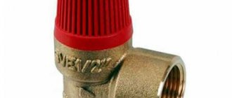
In the market of safety valves for boilers and heating systems, the main niche is occupied by spring safety valves.
Many manufacturers make models in a variety of diameters and with different adjustment ranges. The main purpose of the safety valve is to protect pipeline systems and boilers from overpressure. The advantage of this equipment is its automatic operation. When the set pressure of the coolant is exceeded, the valve opens and begins to discharge excess coolant into the outlet pipeline. When the pressure drops within operating limits, the valve automatically closes and stops discharging the coolant. Spring safety valve device
A spring-type safety valve is a body made of brass or bronze, inside of which there is a safety spring mechanism. This mechanism is based on a steel spring, protected from external influences by a plastic cap, which also serves as a test handle. The test handle allows, if necessary, to manually open the valve to check its functionality. To reliably protect the spring mechanism from coolant getting into it, there is a membrane made of ethylpropylene rubber.
Operating principle of spring safety valve
The principle of operation of a safety valve is based on the mutual opposition of water pressure on the valve, which tends to open the valve, and the spring force, aimed at keeping the valve in the closed position. The safety valve will remain closed until the water pressure at the valve exceeds the spring force. It should be noted that the valve begins to operate at a pressure approximately 3% lower than the set pressure. If the pressure in the system continues to increase, this leads to a further rise of the valve (proportional to the coolant pressure) and a uniform increase in the volume of discharged water. Full opening of the safety valve occurs at a pressure of approximately 110-115% of the set pressure (depending on the model). After releasing the excess coolant, the pressure in the system will begin to decrease and as soon as the spring force of the safety valve overcomes the static and dynamic pressure of the flowing water, the valve will close. Complete closure of the safety valve will occur when the pressure in the system decreases to 80% of the set value.
Setting the Spring Safety Valve
The safety valve is adjusted at the installation site, after completion of all installation work and flushing of the heating system.
The pressure in the spring safety valve is adjusted by rotating a special adjusting screw that compresses the spring, which presses the valve to the seat. After this, the valve response pressure is checked, its full opening and closing.
In some safety valves, the manufacturer has already set and recorded the response pressure at the factory, so independent adjustment of the pressure in them is no longer possible. They have a special non-removable cover that protects against valve reconfiguration. For ease of use, manufacturers introduce color markings on the caps in accordance with the setting pressure: black – 1.5 bar, red – 3 bar, yellow – 6 bar (Valtec VT 490 safety valves).
Manufacturers recommend periodically cleaning safety valves in cases where the heating system operates stably, without overpressure. This is due to the fact that the valve is left idle for a long time, which can cause it to become clogged with various contaminants. To clean the safety valve (“explosion”), you need to turn the cap in the direction of the arrow until it clicks. This procedure allows you to avoid leaks, most of which are caused precisely by clogging and subsequent loose fit of the valve to the valve seat.
Tell your friends about us:
Source
Types of safety valves
In a heating system, a safety valve performs a protective function to prevent high pressure. This is especially important for steam boilers.
Blood pressure rises most often due to the following reasons:
- failure of automatic pressure control systems;
- a sharp increase in ambient temperature and the appearance of steam.
Safety products are mainly of two types:
- spring;
- lever-load.
In lever-load structures, the action of pressure on the spool is counteracted by a load, its force is transmitted through the lever to the rod. It moves along the length of the lever, and in this way you can adjust the force of pressure of the spool against the seat. Then it opens when the working medium begins to press on the lower part of the spool with a force greater than the force of the lever pressure and the water leaves through the pipe.
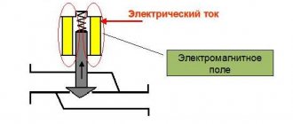
And spring safety units operate using an electromagnetic drive . A spring exerts pressure on the spool rod, and adjustment occurs by changing the degree of compression of the spring.
Small heating systems are best combined with spring products; their advantages in this case are as follows:
- compactness;
- the setting can only be changed when using the tools;
- the spool rod may have different positions;
- Possibility of combination with other products.
According to the principle of operation, safety valves are divided into the following:
- direct action devices;
- indirect;
- two-position.
A direct-acting safety valve can only open under pressure from the working medium, while an indirect safety valve can open only under the influence of a pressure source.
And according to the type of lifting the constipation, the devices are:
- low-lift;
- medium-lift;
- full lift.
Installation and configuration rules
When planning to independently install a safety valve for heating, you should prepare a set of tools in advance. The work cannot be done without adjustable wrenches and wrenches, a Phillips screwdriver, pliers, a tape measure, and silicone sealant.
Before you begin, you need to determine a suitable location for installation. It is recommended to install the safety valve on the supply pipeline near the boiler outlet pipe. The optimal distance between elements is 200-300 mm.
All compact household fuses are threaded. To achieve complete tightness when screwing, it is necessary to seal the pipe with tow or silicone. It is not advisable to use FUM tape, since it does not always withstand critically high temperatures.
In the regulatory documentation that comes with each device, the installation process is usually described step by step.
Some key installation rules are the same for all types of valves:
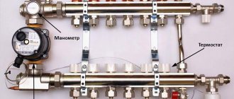
- if the fuse is not mounted as part of a safety group, a pressure gauge is placed next to it;
- in spring valves, the spring axis must have a strictly vertical position and be located under the device body;
- in lever-load equipment, the lever is placed horizontally;
- On the section of the pipeline between the heating equipment and the fuse, the installation of check valves, taps, gate valves, and a circulation pump is not allowed;
- to prevent damage to the body when rotating the valve, you need to select the wrench from the side where the screwing is carried out;
- the drain pipe, which discharges the coolant into the sewer network or return pipe, is connected to the outlet pipe of the valve;
- the outlet pipe is not connected to the sewer directly, but with the inclusion of a funnel or pit;
- in systems where fluid circulation occurs according to a natural pattern, the safety valve is placed at the highest point.
The nominal diameter of the device is selected on the basis of methods developed and approved by Gostekhnadzor. In resolving this issue, it is wiser to seek help from professionals.
If this is not possible, you can try using specialized online calculation programs.
To reduce hydraulic losses during medium pressure on the valve plate, installation of emergency equipment is carried out with a slope towards the boiler installation
The valve adjustment is affected by the type of clamping structure. Spring devices have a cap. The pre-compression of the spring is adjusted by rotating it. The adjustment accuracy of these products is high: +/- 0.2 atm.
In lever devices, adjustments are made by increasing the mass or moving the load.
After 7-8 operations in the installed emergency device, the spring and plate wear out, as a result of which the tightness may be broken. In this case, it is advisable to replace the valve with a new one.
Required tools and materials
To install the valve you will need:
- adjustable wrench;
- fum - ribbon or tow;
- special paste for sealing joints.
Work progress
Each product designed for releasing excess pressure is equipped with installation instructions, which should be carefully studied before starting work. Before installation, you also need to disconnect the water heater from the network and drain the water from it. The valve must be placed on the cold water supply up to the shut-off valve. The valve installation sequence is as follows:
- marking the installation site;
- removing a part of the pipe of a size corresponding to the length of the device body;
- threading the ends of pipes:
- covering the threaded part with tow or fum tape;
- screwing the valve onto the pipe thread;
- connecting to another pipe a pipe leading to the sewer system.
- tightening the threaded connection using an adjustable wrench;
- sealing the joint with a special paste;
- setting up the device in accordance with the passport values (if necessary).
Safety valve installation features
When installing the valve, you must strictly follow all the rules that are listed in the regulatory documentation of the product. Also, the installation must be carried out taking into account the power and operating pressure.
But the key installation principles are:
- carry out preliminary calculations of structural elements;
- Installation is carried out on the supply pipeline next to the boiler;
- It is recommended to place a pressure gauge next to the valve;
- when using a spring design, the spring axis must be vertical and placed above the body;
- The lever of a lever-and-weight valve must be horizontal above the valve;
- in a hot water system, the valve must be installed at the highest point of the water heater at its outlet;
- diameters cannot be narrowed if the valve dimensions do not match the pipeline diameter and for other reasons;
- the connecting pipe should not be too long;
- after connecting to the pipeline, the pipes must be taken to a safe place;
- the valves are adjusted to 20 percent more than the operating pressure of the heating system;
- the check must be performed by forced opening.
We also must not forget that it is necessary to regulate and check the pressure at least once a year before the heating season.
Choice
It is very important to make the right choice of safety valve for the heating system, which will prevent the boiler from boiling and reduce the pressure. For the valve to work correctly, it is necessary:
- Select spring equipment in which the spring will counteract the coolant pressure.
- Decide on the size and type of device so that the pressure in the heating system does not exceed the permissible values, since this is what should help the system operate.
- An open type valve must be selected if water is discharged into the atmosphere, and a closed type - if water is discharged into the return pipeline.
- It is advisable to select a full-lift and low-lift valve based on capacity.
- When discharging water into the atmosphere, it is recommended to install open type devices. For liquid fuel boilers, low-lift valves should be selected, and for gas boilers, full-lift valves.
All power is in pairs.
Steam and condensate systems for industrial enterprises
There are different types of safety valves, so finding a valve that meets your specific requirements is quite easy. Once the appropriate valve type has been selected, the full opening pressure and associated flow capacity must be calculated, and the correct valve size and setting pressure must be selected.
Safety valve setting pressure
To correctly determine the valve setting pressure, you need to know the following parameters: Operating pressure
(WP) – operating pressure in the system under full load conditions during normal operation.
Nominal working pressure
(NRP) – operating pressure at constant rated load.
Design pressure
– sometimes called maximum permissible working pressure (MAWP) or safe working pressure (SWP). This is the excess pressure for which the system is designed. It represents the maximum pressure under normal operating conditions (relative to the maximum operating temperature) of the system.
Maximum pressure increase
(PPD) – pressure exceeding the calculated one by the normative, in %, established value. In a system protected by safety valves, under what conditions can a pressure exceeding the pressure limit be created? In steam systems, the POP is often 10% higher than the MAWP, however this is not always the case. If the MAWP value cannot be immediately determined, you must contact the person responsible for the safe operation of the system or the relevant design organization. If the DPP cannot be obtained, it should in no case be taken greater than the MARD.
Design and principle of operation depending on the type
Lever-load
Lever safety valves are used exclusively in industrial systems and are designed for heavy loads and pipeline diameters over 200 mm.
A weight hung on the lever exerts pressure on the rod. When the force exerted by the pressure in the system on one side exceeds the force exerted by the load on the other side, the rod opens, releasing coolant or steam. As soon as the pressure force inside the system becomes insufficient (it does not reach a critical point), the rod, under the weight of the load on the lever, blocks the system.
Sectional view of a lever-weight relief valve.
Thus, the critical pressure at which it is necessary to release is regulated by the length of the lever and the weight on it.
Spring
A more modern and cheaper option is the spring safety valve. It is not inferior in efficiency to a lever-load type, is reliable and has compact dimensions, therefore it is widely used in individual heating systems of private houses.
A spring relief valve works on the same principle, only instead of a load, a spring acts on the rod:
- from the inside, a flow of water or steam exerts pressure on the valve of the device;
- on the other side there is a spool pressed by a rod, which is acted upon by a spring;
- the pressure in the system exceeds the clamping force of the spring, the spool rod rises up, and depressurization occurs;
- coolant or steam exits through the outlet pipe;
- the pressure inside the system decreases and becomes lower than the pressing force of the spring, which closes the shutter again, returning the mechanism to its original position.
The operating principle of a spring safety valve designed for an individual heating system.
There are both valves designed for a specific pressure (for example, 3, 6 or 8 bar) and adjustable valves, the critical pressure for relief is set during installation. They can also be open or closed. The first ones discharge water or steam into the external environment, closed valves - into the pipeline connected to them.
Thermal relief valves
Spring-loaded safety valves are also imperfect. In addition to the fact that they work exclusively in closed systems (since boiling of the coolant in a system with an open expansion tank can occur without increasing pressure), spring mechanisms are triggered when the temperature of the coolant has already exceeded a significant level - over 95-100 ° C.
The most effective, but extremely expensive, is the thermal relief valve, which responds to an increase in the temperature of the coolant, and not the pressure in the system. The principle of operation is the same membrane, which is controlled by a spring, but it is driven not by the pressure of the water flow, but by a heat-sensitive liquid that expands significantly when heated by the coolant.
Installing a pump in a heating system: placement, insertion method and other details
How to properly install a pump in a heating system that already operates using natural circulation?
How to install a pump in a heating system being designed for a new home? Which shut-off valves can be used and which ones should not? Let's try to find out.
Are there any subtleties to organizing forced circulation in the heating circuit? Let's find out together.
Why do you need a pump?
Let's start with the main thing: find out whether it is necessary to install a pump on the heating if it has been working properly without it for many years. What will change?
pros
- The inertia of the system will sharply decrease. If, with natural circulation, at least an hour can pass between the ignition of the boiler and the noticeable heating of radiators far from it, then with forced injection of coolant, the house will begin to warm up within a matter of minutes.
- The temperature of the heating devices will level out. A feature of any gravity system is the unequal heating of radiators closest to the boiler and those farthest from it. The coolant, which circulates rather slowly, manages to cool down before it completes a full circle around the circuit.
- If, when laying pipes, they are mounted somewhere with a negative slope, this will not affect the circulation. Installing a pump in the heating system will sharply increase the pressure drop, and the air pockets that are inevitable during a counterslope will no longer be a hindrance.
However: continuous gurgling when there is air in the circuit can be annoying. Functionality is functionality, but it is still better to take care of the possibility of venting air from everywhere.
Minuses
Are there any downsides to systems with a circulation pump?
- The price of a kilowatt-hour of electricity is growing steadily, and the pump consumes it. Albeit a little - no more than 100 watts at maximum speed.
This device has three operating modes: 55, 70 and 100 watts.
- If the heating system is designed only for forced circulation, the very first long power outage will have an extremely unpleasant surprise in store for the home owner. Overheating of the coolant by the boiler can cause destruction of the heating circuit, and stopping circulation can lead to subsequent defrosting.
conclusions
If doing something with the electricity consumption of an electric pump is, by definition, problematic, then the second problem can be solved. Moreover, the solution is obvious: when designing a system, it is necessary to include in the design the ability to work using natural circulation.
Installing the pump
Position relative to the horizon
How to install a heating pump correctly in terms of its service life? Surely there are factors that can lead to accelerated wear of the mechanics.
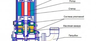
The instructions are related to the operating features of the mechanical part of the device. The design of a heating pump, used to create individual heating systems of moderate power, involves continuous cooling of the rotor and shaft with bearings by circulating coolant.
To prevent air locks from leaving the bearings without lubrication and cooling, the motor shaft must be positioned strictly horizontally.
Correct and incorrect pump positions.
Water filtration
It is highly advisable to install a sump tank in front of the pump. Its function is to filter out the inevitable sand, scale and other abrasive particles that destroy the impeller and bearings of the circulation pump.
Since the diameter of the pump insert is usually small, an ordinary coarse filter is quite suitable. The barrel intended for collecting suspended matter should be directed downwards - this way it will not interfere with the circulation of water, even when it is already partially filled.
Attention: on most filters, an arrow indicates the recommended direction of water circulation when installing it. Yes, the filter will perform its function even if installed incorrectly; however, you will have to clean it much more often, and it will be much more difficult to remove ALL the sediment.
Pump location in the circuit
Where, in what part of the circuit is it recommended to install a heating pump?
Formally, modern pumps work equally well on both supply and return in any part of the heating circuit. However:
- The higher the temperature of the coolant, the lower the service life of the bearings and all plastic parts of the device. From this point of view, it is still necessary to embed it on the return pipeline, directly in front of the boiler.
- It is recommended to install the expansion tank in a section of the circuit with the coolant flow as close to laminar as possible. After the pump, the flow will inevitably be turbulent. Hence the second amendment: the circulation pump cuts in before the boiler and after the expansion tank.
The optimal condition for an expansion tank is a water flow with a minimum of turbulence. Before the pump, the flow in the circuit is almost laminar.
Bypass
Remember our thoughts that it is highly desirable for the heating to work even when the electricity is turned off? Albeit with less efficiency?
How to install a heating pump with your own hands so that it does not interfere with natural circulation?
Let's think out loud for a bit. The gravity system is characterized, first of all, by a minimal difference between supply and return. Therefore, for an acceptable circulation rate, a minimum hydraulic resistance of the circuit is required.
What increases it?
- Rotations and bends of the contour.
- ANY shut-off valves.
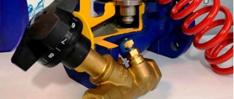
By the way: it is from this point of view that only modern ball valves should be used in any autonomous heating system. Unlike their screw counterparts, they offer minimal resistance to water flow when open. To understand why this is so, take a look at an open valve of this type.
When the valve is open, the lumen in it does not differ from the lumen of the pipe. In addition, there are no bends and turns where the difference is lost.
- Reducing the pipe diameter.
Conclusions?
- The pump runs parallel to the main circuit without breaking it. For the gravity system to operate, the diameter of the circuit must be no less than DN32; The diameter of the pump insert is much smaller.
- A valve is installed between the taps, completely shutting off the main circuit when the pump is operating. Otherwise, it will work, driving water in a circle between cuts.
- Valves are installed before and after the pump, allowing you to cut off the faulty device and dismantle it in the event of a malfunction without resetting the entire heating.
This insertion scheme has a weak point - the need to manually switch from the pump to the bypass when turning off the light. Yes, if you are at home, it is difficult not to notice a power outage; but what if everyone in your household is away?
The solution is a check valve. In normal mode it closes; as soon as the pressure in the main circuit before the pump becomes greater than after it, the valve is open. As always, there are subtleties.
All spring check valves give a noticeable loss of pressure: the water needs to overcome the resistance of the spring. Which, of course, goes against our goals. The outlet is a ball valve mounted horizontally. Its resistance to water flow will be minimal, as will the pressure required to open the valve.
The circuit in the photo will switch from forced to natural circulation without your participation.
Conclusion
You will find some additional information and recommendations for installing the devices that interest us in the video at the end of the article. Warm winters!
Safety relief valve selection criteria
Clamping mechanism
Lever-load safety valves are designed for heavy loads and a pipe diameter of at least 200 mm, therefore they are used in industrial heating systems.
For individual heating of a private house, it is better to purchase a device with a spring mechanism; this is a standard, reliable and frequently used type of relief valve.
Lifting height
Pressure relief valves have different valve lift heights:
- Low-lift model PS-350. Low-lift. The height of the shutter in low-lift valves does not exceed 1/20 of the seat diameter. They have a relatively low throughput and a simple design. Used in lines with liquid coolant. As a rule, low-lift safety valves are sufficient for a heating system with a water circuit with a power of up to 40-43 kW. To prevent an accident in such systems, it is necessary to discharge a small volume of coolant.
- Full lift. The height of the valve in full-lift valves is greater than or equal to the diameter of the seat. As a rule, these are lever-load mechanisms, more expensive and complex in design. Full-lift valves have a high capacity and can be installed on lines in which gases, steam or compressed air circulate.
Full lift model PN 16.
Mechanism response speed
Based on response speed, safety valves are divided into proportional and on-off.
In heating systems of a private home, it is better to use proportional valves; again, they are sufficient for most systems. The shutter cover of such devices opens gradually, in proportion to the increase in pressure in the line, and accordingly, the volume of coolant discharged increases proportionally. Such valves do not self-oscillate, they maintain the correct pressure level and are cheaper.
Two-position safety valves are distinguished by instantaneous detonation and full opening of the valve. This mechanism allows you to quickly release large volumes of coolant, but creates the risk of water hammer: due to the rapid release of a large amount of coolant liquid, the pressure in the line significantly decreases, after which the valve closes sharply. Therefore, it is recommended to install two-position safety valves on lines with a compressible medium (air, gas, steam).
Diameter
The diameter of the pressure relief valve in the heating system should not be less than the connector of the supply pipe. Otherwise, the constant hydraulic pressure will interfere with the operation of the mechanism.
Manufacturer
Since safety valves have a fairly simple design, and modern models are in most cases made of brass using the same technology, there are no critical differences between valves from different manufacturers.
What is the purpose of a bypass valve in a pipeline?
During operation of heating or water heating systems, the volume of the working medium may change.
An increase or decrease in coolant pressure negatively affects the performance of the heating circuit: it can lead to uneven heating, airing of system components, and breakdowns. Changes in the pressure of the working environment also affect comfort: the temperature in the rooms changes uncontrollably, and the pipes begin to hum and vibrate . To prevent this from happening, it is important to maintain a pressure balance in the pipeline
It is not difficult to constantly monitor the pressure, bleed or add coolant manually, but it is better to entrust this routine work to automation.
There are several types of control valves that cope with this task better than a person.
The bypass, or overflow, valve allows you to stabilize the pressure in the pipeline by redirecting the working fluid through an additional branch of the pipeline, called a bypass.
Regulation does not occur by one-time or periodic bleeding of excess coolant, but in portions, due to which the pressure of the liquid or gas is constantly maintained at the same level.
The device can and should be equipped with pipelines of any complexity, but most of all they need pressure adjustment:
multi-circuit heating systems - if one of the circuits is turned off, coolant consumption decreases and pressure increases, which can cause pipeline breaks, overload the pump and heat-generating device - to avoid this, you need to reduce the pressure and maintain it at the required level; heating systems equipped with thermostats and hot water supply systems - when setting the temperature, the volume of coolant consumed changes, and it is necessary to quickly restore the pressure balance in the circuit; water supply systems equipped with storage-type water heaters - in the boiler and pipeline the water is under high pressure, and since the volume of supplied liquid changes jerkily due to constant adjustment and frequent turning on and off of water, it is especially important to regulate the pressure of the working medium so that an accident does not occur and The water heater is broken.
Types of security groups and the principle of choosing the appropriate model
A standard safety valve for a boiler may differ in design in several design features. These nuances do not change the functionality of the device, but only simplify use and maintenance. To choose the right safety unit, you need to know what safety valves for boilers are and how they differ.
Lever models
The most common type of standard safety assembly is the lever model. This mechanism can be activated manually, which is convenient when checking or draining water from the boiler tank. They do it like this:
- A horizontally located lever is installed vertically;
- direct connection to the stem activates the spring mechanism;
- the safety valve plate forcibly opens the hole and water begins to flow from the fitting.
Even if the tank is not completely emptied, a control drain is performed monthly to check the functionality of the safety unit.
The products differ in the design of the lever and the fitting for discharging water. If possible, it is better to choose a model with a flag fixed to the body. The fastening is made with a bolt that prevents children from manually opening the lever. The product has a convenient herringbone-shaped fitting with three threads, which ensures reliable fixation of the hose.
The cheaper model does not have a flag lock. You can accidentally catch the lever with your hand and unnecessary drainage of water will begin. The fitting is short, with only one threading ring. It is inconvenient to fix the hose onto such a protrusion and can tear it off under strong pressure.
Models without lever
Safety valves without a lever are the cheapest and most inconvenient option. Such models often come complete with a water heater. Experienced plumbers simply throw them away. The units operate similarly to lever models, but there is no way to manually perform a control drain or empty the boiler tank.
Models without a lever come in two versions: with a cover at the end of the body and blind. The first option is more convenient. If clogged, the cover can be unscrewed to clean the mechanism. A blind model cannot be tested for functionality and cannot be descaled. The fluid discharge fittings for both valves are short with one threaded ring.
Safety components for large water heaters
Water heaters with a storage tank volume of 100 liters or more are equipped with improved safety valves. They work in a similar way, only they are additionally equipped with a ball valve for forced drainage, as well as a pressure gauge.
Particular attention should be paid to the fluid drainage fitting. It's threaded. Reliable fastening prevents the hose from being torn off by strong pressure and eliminates the inconvenient use of the clamp
Reliable fastening prevents the hose from being torn off by strong pressure and eliminates the inconvenient use of the clamp.
Original models
For lovers of aesthetics and comfort, manufacturers offer original safety components. The product is equipped with a pressure gauge, chrome plated, and given an elegant shape. The products look beautiful, but their cost is high.
Difference in body markings
High-quality products must be marked on the body. The manufacturer indicates the maximum permissible pressure, as well as the direction of water movement. The second marking is an arrow. It helps to determine which side to place the part on the boiler pipe.
On cheap Chinese models there are often no markings. You can figure out the direction of the liquid without an arrow. The check valve plate must open upward in relation to the boiler pipe so that water from the water supply flows into the tank. But it’s impossible to determine the permissible pressure without markings. If the indicator does not match, the safety unit will constantly leak or will not work at all in an emergency.
Other types of valves
When they try to save money on a safety group, they try to install a blast valve designed for the heating system on the water heater. The nodes are similar in functionality, but there is one nuance. The blast valve is not capable of releasing liquid little by little. The mechanism will work when the excess pressure reaches a critical point. The blast valve can only release all the water from the tank in the event of an accident.
Separately, it is worth considering installing only a check valve. The mechanism of this unit, on the contrary, locks the water inside the tank, preventing it from draining into the pipeline. If there is excess pressure, the working plate with the rod is not able to work in the opposite direction, which will lead to rupture of the tank.
The act of setting
The act of setting up the safety valve is a mandatory document. It is written on each valve. The form of the act can be adjusted.
If the conditions for adjusting the device change, then entries must be made in the document. All points in the form must be filled out. If there is no separate data, they write: “ No data required .” The act also indicates the commission that accepts the readiness of the device for operation. At the end of the document, the signatures of the members of this commission are required.
If you do not limit the heating of water in the boiler, it will boil and turn into steam, which will lead to a critical increase in pressure in the heating network. This is followed by a rupture of the pipeline or water jacket of the heat generator. To avoid the described emergency situation, a safety valve for heating is installed at the boiler outlet, releasing excess pressure from the system. Our publication is devoted to the selection and installation of this important element.
Design features and sizes
PSK cannot be manufactured in a handicraft way; products are produced in factory conditions in accordance with the requirements of GOST or TU.
The material must be durable, wear-resistant, not prone to deformation from changes in operating conditions, and not susceptible to the negative effects of corrosion. Most often it is brass or aluminum, but devices are also made from cast iron and stainless steel.
The design of products from different manufacturers may vary, but the most common type is a cone-shaped device with a seat, equipped with fasteners for installation in the pipeline
There are two threaded holes in the housing. Their diameter depends on the type of PSC and is usually 1″ or 2″. For household networks, mainly two types of valves are used, differing in cross-section - 25 mm or 50 mm.
Table with technical characteristics of PSK. Devices may differ not only in cross-section, but also in the type of connection to the pipeline, operating pressure, material of manufacture, housing dimensions
The principle of operation of the protective gas valve is simple: as soon as excess gas enters the device and begins to put pressure on the membrane, it acts on the spring, which opens the outlet to the outside. As soon as the pressure drops to operating parameters, the spring closes the hole.
Although the devices operate automatically, they are equipped with a forced opening mechanism. This is necessary to check the performance of the valve.
To perform testing, you need to pull a special element of the device - the rod. This manipulation should be repeated several times to make sure that the mechanism works.
The shut-off and control valve is mounted in tandem with the valve so that, if necessary, if the valve suddenly does not work, the gas supply can be quickly shut off.
Rating of lifting products
More expensive products with a coolant blocker in the form of a spool.
Zetkama V277 Du-15
Characteristics:
- nominal diameter – 15 mm;
- connection – threaded (P/P);
- material – cast iron;
- maximum temperature - 200 °C;
- working pressure – 16 bar;
- price – 2798 rub.
The device is installed on pipelines intended for transporting cold and hot water for technical purposes, neutral media, and steam. Installation is carried out horizontally or vertically.
Armafit 16kch9p - DU32 Ru25
Characteristics:
- working pressure – 1.6 MPa;
- maximum temperature – 225 °C;
- connection – flange;
- working media – steam, water;
- temperature conditions of use – from -30 to 50 °C;
- price – 3650 rub.
Unit with flange connection to block steam and water flows. The version with a rubber spool seal can operate at temperatures up to 50 °C, and with a paronite or bronze seal - up to 225 °C. The cover and main structure are made of cast iron, the spool is made of steel.
Purpose, device, classification of PZK
An increase or decrease in gas pressure after the pressure regulator beyond the specified limits can lead to an emergency. If the gas pressure increases excessively, the flames of the burners may come off and an explosive mixture may appear in the working volume of the gas-using equipment, seal failure, gas leakage in the connections of gas pipelines and fittings, failure of instrumentation, etc. A significant decrease in gas pressure can lead to the penetration of the flame into the burner or the extinguishing of the flame, which, if the gas supply is not turned off, will cause the formation of an explosive gas-air mixture in the furnaces and flue ducts of the units and in the premises of gasified buildings.
The reasons for an unacceptable increase or decrease in gas pressure after the pressure regulator for dead-end networks are:
- malfunction of the pressure regulator (jamming of the plunger, formation of hydrate plugs in the seat and body, leakage of the valve, etc.);
- incorrect selection of the pressure regulator according to its throughput, leading to an on-off mode of its operation at low gas flow rates and causing surges in output pressure and self-oscillations.
For ring and branched networks, the reasons for unacceptable pressure changes after the pressure regulator may be:
- malfunction of one or more pressure regulators supplying these networks;
- incorrect hydraulic calculation of the network, due to which abrupt changes in gas consumption by large consumers lead to surges in output pressure.
A common reason for a sharp drop in pressure for any network may be a violation of the tightness of gas pipelines and fittings, and therefore a gas leak.
To prevent an unacceptable increase or decrease in pressure in the gas distribution system (GRPSH), high-speed safety shut-off valves (SSV) and safety relief valves (PSV) are installed.
SCPs are designed to automatically stop gas supply to consumers in the event of an increase or decrease in pressure above specified limits; they are installed after pressure regulators. SPDs are triggered in “emergency situations”, so their spontaneous activation is unacceptable. Before manually turning on the shut-off valve, it is necessary to detect and eliminate malfunctions, and also make sure that the shut-off devices are closed in front of all gas-using devices and units. If, due to production conditions, an interruption in the gas supply is unacceptable, then instead of a shut-off valve, an alarm system should be provided to alert service personnel.
PSK are designed to discharge into the atmosphere a certain excess volume of gas from the gas pipeline after the pressure regulator in order to prevent pressure from increasing above a predetermined value; they are installed after the pressure regulator on the outlet pipeline.
If there is a flow meter (gas meter), the PSK must be installed after the meter. For GRPS, it is allowed to take the PSK outside the cabinet. After the controlled pressure is reduced to a predetermined value, the PSC must close hermetically.
Valve operating conditions
After checking and revision, the valves are adjusted and undergo the necessary adjustment to the specified pressure. Then the device is sealed. Installation without a seal is strictly prohibited. All safety valves have a technological passport or “operation cards”.
The service life of safety valves directly depends on proper operation and maintenance. Various defects often arise during operation.
Among them are the following common defects:
- a leak
- pulsation
- bullies
A leak is characterized by the loss of a working medium. Occurs when the seals are damaged and foreign objects get on them. And also when the spring is deformed. It can be eliminated by purging, lapping, replacing the spring, correct installation or new valve adjustment.
Pulsation - opening/closing too frequently. Occurs when the cross-section is narrowed or the throughput is high. The problem is eliminated by correct selection of the necessary parameters.
Scouring during operation occurs as a result of distortions during assembly. They can be eliminated by mechanical processing and further correct assembly.
Final tips
If you are keenly interested in the safety of the boiler room and the reliable operation of heating equipment, then we recommend that you carefully study the range when purchasing fittings. The fact is that new useful products are appearing on the market that cannot be reviewed within the scope of this article, but they may be useful to you.
Operating moment. Monitor the condition of safety valves in order to detect activation in time and understand the reasons. Direct the heat release devices into the sewer funnel with a burst of stream - an unexpected splash of water in the boiler room and wet footprints will make it clear that an emergency situation has occurred.
Why are valves on batteries needed?
Valves are also installed on radiators and circuit batteries, but their main function is to remove air from the system.
The installed valve for the heating radiator can be manual or automatic. The manual valve is opened and closed manually using a key and screwdriver.
The automatic valve on the heating radiator does not require human intervention. It removes air perfectly, but its main drawback is its sensitivity to blockages due to contamination of the coolant. To remove dissolved air from the coolant and clean it of dirt and sludge, it is recommended to install air separators.
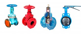
Varieties
Existing types of valves are capable of working with boiler equipment from leading foreign (Vaillant, Baxi, Ariston, Navien, Viessmann) and domestic (Nevalux) manufacturers using gas, liquid and solid fuels in situations where automatic control of the system operation due to the type of fuel is difficult or broken when the automation fails. Depending on their design and operating principle, safety valves are divided into the following groups:
- According to the purpose of the equipment in which they are installed:
- For heating boilers that have the above design, they are often supplied on fittings in the form of a tee, into which a pressure gauge is additionally installed to check the pressure and a venting valve.
- For hot water boilers, the design includes a flag for draining water.
- Tanks and pressure vessels.
- Pressure pipelines.
- According to the operating principle of the clamping mechanism:
- From a spring, the clamping force of which is regulated by an external or internal nut (its operation is discussed above).
- Lever-load type, used in industrial heating systems designed to discharge large volumes of water; their response threshold can be adjusted by hanging weights. They are suspended on a handle connected to the shut-off valve using a lever principle.
Lever-load modification device
- Locking mechanism speeds:
- Proportional (low-lift spring) - the sealed lock rises in proportion to the pressure and is linearly related to its increase, while the drain hole gradually opens and closes in the same way with a decrease in the volume of coolant. The advantage of the design is the absence of water hammer under various modes of movement of the shut-off valve.
- Two-position (full-lift lever-load) - operate in open-closed positions. When the pressure exceeds the response threshold, the outlet hole opens completely and the excess coolant volume is released. After the pressure in the system is normalized, the outlet is completely blocked; the main drawback of the design is the presence of water hammer.
- By adjustment:
- Non-adjustable (with caps of different colors).
- Adjustable screw parts.
- According to the design of the spring compression adjusting elements:
- An internal washer, the operating principle of which was discussed above.
- External screw, nut, models are used in domestic and communal heating systems with large volumes of coolant.
- Using a handle, a similar adjustment system is used in flanged industrial valves; when the handle is fully raised, it is possible to perform a one-time release of water.
Designs of various models of drain valves
Purpose
The relief safety valve protects the heating system from the consequences associated with overheating of the coolant. This device is a necessary attribute of the piping of a solid fuel boiler, and is also part of the heating system with a heat exchanger installed in the furnace.
Unlike liquid fuel, gas and electric boilers, solid fuel units are characterized by great inertia and the inability to quickly regulate the heating intensity of the liquid in the water jacket or heat exchanger. When overheated, the coolant boils, and as a result of vaporization, the pressure in a closed volume increases sharply.
This could turn out to be
:
- leaks at the junctions of pipeline elements;
- damage to fittings and pipes made of polymer material;
- explosion of the boiler water jacket, which is dangerous for people and can cause a short circuit of electrical equipment in the boiler room.
An overpressure relief valve can be installed separately, but usually this device is part of a safety group complete with a pressure gauge and air vent.
Valve Installation Requirements
A device for removing excessive water pressure is installed taking into account the expansion tank in the heating system. The safety valve is activated after the volume of the membrane tank is exhausted. The mechanism is placed on a pipeline connected to the boiler pipe. The approximate distance is 20 – 30 cm.
In this case, the following conditions must be met:
- If the valve is installed separately from the safety group, it is first necessary to install a pressure gauge to monitor the pressure.
- Valves, taps, and pumps must not be installed between the valve and the heating unit.
- A pipe is connected to the valve (outlet pipe) to drain excess coolant.
- It is recommended to install the protective mechanism at the highest point of the coolant circulation system.
- The protection device must be replaced after seven or eight operations due to loss of tightness.
Installation rules
Installation rules
When installing a check valve, several important points must be taken into account:
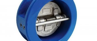
- The product is placed only in the direction of liquid flow. To make it easier to select the correct side, there is a special arrow-shaped marking on the valve body.
- For better fixation of devices, it is permissible to use paronite seals, but only if they do not narrow the bore diameter of the pipe, otherwise the pressure on the system will be excessively increased.
- The part is placed in such a way that other parts of the pipeline structure do not create additional load on its body.
- It is advisable to install a special mesh in front of the shut-off device for the initial cleaning of the coolant. It will trap large particles that can weaken the seal of the unit when they enter the mechanism.
For lines with forced circulation, any types of check valves can be used, and for gravity circuits, only rotary-type petal models that do not have a spring are applicable.
The locking mechanism must be installed on multi-circuit systems equipped with a circulation pump.
It is also necessary to install the valve on heating circuits with bypass. As a rule, they are created for the transition from gravitational circulation to artificial circulation. The valve is fixed on the bypass in a position parallel to the circulation pump.
Heating circuit with bypass
It is also recommended to install shut-off valves on the make-up system. This will prevent the pipeline from emptying in various situations. For example, opening the tap on the make-up pipe to increase pressure, if at this time the water supply is blocked, can lead to complete drainage of the system and shutdown of the boiler.
Choosing the right valve is also important. To block unwanted flows, petal or disk units should be installed between adjacent circuits. The first option will create less resistance, which is also important to consider during installation.
Expert opinion
Grebnev Vadim Savelievich
Heating system installer
When assembling the bypass unit, it is better to use a ball valve model. It has minimal hydraulic resistance. For the recharge system, it is more reasonable to use disk devices with a good supply of operating pressure.
A check valve is not required for all types of heating equipment. But it is necessary for the formation of bypass circuits and multi-circuit systems. When choosing, you should take into account the characteristics and features of individual models, as well as their connection options.