Protective pipeline fittings are found everywhere in our lives. In any house, at any factory, gas station, oil well, farm, boiler room, and even at the water supply to the apartment, check valves are used everywhere to protect the system and equipment from the reverse flow of water, gas, fuel and many other fluids.
We welcome our reader and bring to his attention an article about the types of protective fittings for pipelines.
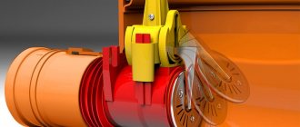
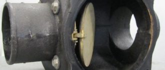
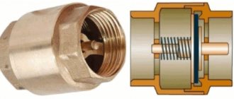
Wafer check valve is a compact and effective valve that protects networks and equipment.
What is it and what is it for?
A check valve is a protective pipeline fitting that allows the flow of a medium to flow in one direction and blocks the movement of a medium in the opposite direction. It is a direct-acting valve and is activated automatically by the return movement of the working medium.
By design, check valves are divided into:
- for ball or receivers;
- check valves;
- wafer;
- combined (combined with shut-off valves).
Wafer products are characterized by compact dimensions and installation method - in flanged pipeline breaks.
Materials
Wafer check valves are made of cast iron and painted red. The outside and inside of the product has an anti-corrosion coating made of thermosetting epoxy resin.
The valve consists of the following elements:
- body (cast iron 65-45-12);
- leaf valve (cast iron 65-45-12);
- stem (420 stainless steel);
- spring (304 stainless steel);
- seals (EPDM).
Purpose and scope of application
With the help of check valves, pipeline systems, equipment, pumps, heating boilers, and automation are protected from water hammer; if a seal is broken or part of the system is destroyed, they reduce leakage.
In technological schemes, check valves are used:
- in closed systems for make-up;
- after installing meters and other control and measuring equipment;
- in systems with several pumps;
- in heating systems on the jumper between the supply and return pipelines;
- in all kinds of supply pipelines where the movement of the medium in one direction is required;
- in ventilation systems;
- in filter systems, treatment facilities - to ensure the movement of liquid through the filter or only in one direction;
- in everyday life - in wells together with a deep submersible pump, in quick-release couplings of irrigation systems, in thermostatic fittings for heating systems in private homes.
The areas of application of protective fittings are in all areas of industry, mining, everyday life, agriculture, transport, and the gas transmission system.
Check valves are used in systems with both liquid and gaseous media.
Controls and technical characteristics
Connection type
Wafer check valves can be installed in pipelines in both vertical and horizontal positions.
The design feature of connecting such valves is that they do not have flanges for installation in the pipeline - they are clamped between the pipeline flanges.
Device
Wafer designs are characterized by the absence of flanges. In their body there is a working element - a disk, flaps, which, when the flow of the medium changes to reverse, block the passage and prevent the reverse flow of gases and liquids.
Operating principle
The principle of operation of check valves is based on the fact that in the absence of medium flow, the working body (disk, spool, ball) under the influence of its own weight and additional devices moves to the “closed” position (sits in the housing seat).
When a flow occurs, the valve under its pressure moves to the “open” position and opens the passage through the seat. If the flow of liquid or gas changes position to the opposite, it stops, the valve moves to the closed position, then the pressure of the liquid or gas additionally presses the spool, ball or disk - the passage is securely blocked.
The check valve is activated automatically under the influence of the moved medium, without additional control or regulation.
Types and designs
Structurally, wafer check valves are either double-leaf or spring disc.
Spring-operated disc models (sometimes called single-leaf) have a shutter in the form of a flat disc, which, in the closed position, is pressed against the body seat by a spring.
The thin disk takes up little space in the case, which greatly reduces the weight and overall length of the mechanism. The use of a spring and the light weight of the disk make it possible to install the fittings in both vertical and horizontal positions.
Such models are installed on pipelines with a working diameter of 15-200 mm.
Double-leaf models are more reliable than disk models and are used in more complex and larger systems with working diameters from 50 to 700 mm.
In a double-leaf check valve, the gate elements are two flaps (segments or petals) mounted on an axis. The axis runs through the center of the passage, and springs are attached to it.
In large hydraulic or pneumatic systems, dangerous water hammer often occurs (during emergency situations, pump shutdowns, etc.). In such cases, valves with shock absorbers are used to dampen sudden pressure surges in the hydraulic system.
Check valves, based on the material from which they are made, are:
- made of structural alloy steel;
- stainless steel;
- made of brass and bronze;
- made of cast iron;
- made of titanium;
- made of aluminum;
- made of bronze;
- combined.
In the marking, in second place are the letters that indicate the material.
Symbol
Based on the current GOST No. 24-8-56, any pipeline fittings require a symbol, and the designations are carried out according to the following scheme: type of fittings used - type of mounted fittings - design features (type) - DN - PN. For example, the unit may contain the following entry: flanged rotary check valve 19xxx53xxx, where the first numbers indicate the type of fittings used, then the material from which the body is made, the features of the material used (alloy steel), the model number and the material of the seals used will be indicated. However, other designations may also occur, because in most cases everything will depend on the manufacturer, who makes the marking at his own discretion.
The working environment category should include:
- gaseous media;
- liquid media (aggressive);
- slightly aggressive environments;
- non-aggressive environments;
- petroleum products;
- oil;
- gas;
- oil;
- steam;
- water.
Can be used at temperatures from -196°C to +565°C. But pressure indicators can differ significantly, because everything will depend on the type of equipment chosen. The working pressure is indicated in GOST No. 356, and the nominal pressure can be found in GOST No. 26-349. Other valve characteristics can also be found on the modern market.
The main differences will be:
- nominal diameter;
- design temperature;
- back pressure;
- control pressure;
- pressure required for opening;
- pressure required for adjustment;
- pressure for optimal closure;
- design pressure.
Many other characteristics are listed in GOST R-52-720 and 24-856. The climatic design is also different, but remains within the limits specified in GOST 15-150-69. The most common designations are UHL, HL, U for different locations, for example, indoors. The requirements for the material that will be used in the production of individual parts will depend on this.
Advantages and disadvantages
Advantages:
- small dimensions, including construction length;
- light weight;
- affordable price;
- possibility of installation on both vertical and horizontal sections of the pipeline;
- simple design;
- reliability;
- does not require maintenance;
- good maintainability.
A significant disadvantage of wafer-type products is a significant loss of pressure on the valve (since there is a working element in the passage - a valve with an axis, a disk). When installing in large hydraulic systems, it is necessary to take into account the pressure loss in the calculations of system parameters. Disc models inhibit the flow of the medium more strongly than sash models. Disc models do not work well in conditions where the liquid contains impurities, such as sand.
Please note that check valves do not replace conventional shut-off valves and gate valves.
Advantages of valves
- Simple on-line installation.
- Equipment reliability.
- Durability of work.
- Minor loss of pressure.
- Relatively low price.
- Compact dimensions.
- Light weight.
- High maintainability.
- Minimum maintenance requirements.
When choosing equipment, it is necessary to take into account the diameter of the water supply, the working environment, the temperature range and the planned pressure. If you are in doubt about the selection of equipment, contact our consultants. They will help you complete your order and advise on current technical specifications.
Tips for choosing
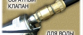
In practice, in everyday life we may encounter the installation of a coupling check valve (clutch valve) after the water meter and at the inlet of the heating system. Choosing a shutter for a meter makes virtually no sense - they are sold everywhere and produced in every region. The technology and design are also the same everywhere. Material: brass. The main thing is to buy it in a store, with a receipt, a guarantee, and inspect it visually. The most important thing is that the nominal diameter coincides with the diameter of the water meter!
Work on the heating system input must be carried out by utility specialists. But it is likely that under certain conditions the residents of the house will still have to buy and select components for the input unit. The most important thing is to purchase from a construction hypermarket, with a guarantee, the required nominal diameter. The choice of materials is very important: the ideal, but expensive option is stainless steel or brass.
The best option in terms of price/quality ratio - structural steel with a stainless steel working body - also works well and lasts a long time.
Rules for installation and operation of the device
Required tools and materials
To install a check valve behind a water meter, you need: the valve itself, gaskets of the required diameter (preferably made of silicone), two adjustable wrenches, FUM tape.
Connection diagram
The valve is installed immediately behind the meter.
When installing, you must ensure that the direction of water flow coincides with the arrow on the device body.
Work progress
Installation procedure:
- the water meter pipe with the union nut is disconnected from the water meter;
- the threads of the pipe of the intra-apartment or intra-house network and the water meter pipe are carefully wrapped with FUM tape;
- screw the pipe into the valve;
- screw the valve onto the thread of the internal network, the arrow of the direction of water flow should be directed away from the meter;
- a gasket is installed in the union nut;
- screw the nut onto the connecting pipe of the meter;
- Let the water flow and test the connection; if there is a leak, tighten the connections.
We suggest watching the video for installing a check valve on a water meter:
Frequent errors and problems during installation
In practice, there can be only one mistake: installation is not in the direction of water movement. And there may still be leaks.
When installing the valve in the opposite direction, water will not flow into the meter and the apartment - you will have to unscrew it and reinstall it. In case of leaks, tighten the connections.
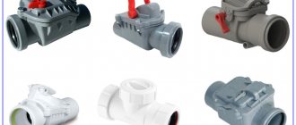
Types of shutters
- single-disk rotary - mounted on pipes of any direction. Made from cast iron. The connection is flangeless - the pipe is tightened with local flanges. Flow medium: vapor, liquid.
- reverse rotary - mounted on vertical or horizontal pipes. The design feature does not allow it to be used in a pulsating flow. Made of steel. Connection type – wafer. Working medium: aggressive liquid, oils, heavily contaminated.
- reverse rotary with clapper is installed in working environments: sewage water or water with solid particles of garbage. Made of steel. Connection type – flange.
- reverse rotary with welded ends is made of carbon steel. Works in: vapor, liquid, and chemically neutral substances.
- reverse rotary flange is mounted on pipes of any direction. Made from gray cast iron. Connection type: flange. Working medium: water, steam, oil and oil products, oil.
Expert advice
When installing a water metering unit, especially in a steel water supply system, it may be inconvenient to install - there will not be enough space to screw on the union nut at the last moment. In this case, it is worth supplementing the metering unit with another union nut - an “American” one on the valve side (of the “nut-fitting” type).
Do not be afraid to install a check valve on the metering unit yourself. This is quite affordable for the novice home DIYer.