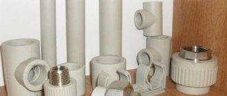
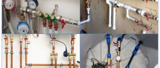
Plumbing systems are a type of engineering systems that include water supply, sewerage, heating, ventilation, air conditioning, and gas supply.
GOST 21.205-2016 establishes the basic graphic designations of elements of engineering support systems, thermomechanical and other pipeline systems, as well as alphanumeric designations of pipelines of these systems in drawings and diagrams when designing buildings and structures for various purposes.
Pipeline symbols
At the design stage of buildings, enterprises and structures for various purposes, pipelines and their individual elements are depicted on construction drawings, diagrams of thermomechanical and technological solutions, networks and engineering support systems (heating, sewerage, cold and hot water supply, gas supply, ventilation and air conditioning) using graphic symbols and simplified graphic images. They are established by the state standard GOST 21.206 - 2012.
| Pipe designations | ||
| Simplified image | Symbol | Name |
| Pipeline | ||
| Piping with a vertical riser pointing downwards or an outlet pointing away from the reader | ||
| Pipeline with a vertical riser pointing upward or a branch pointing towards the reader | ||
| Flexible pipeline | ||
| Crossing pipelines without connection | ||
| Connection of general purpose pipelines | ||
| Flange connection of pipelines | ||
| Coupling threaded connection | ||
| Union threaded connection | ||
| Threaded quick release coupling | ||
| Socket connection of pipelines | ||
| Pipe end with general purpose plug | ||
| Flange end of the pipeline | ||
| Coupled threaded end of the pipeline | ||
| Threaded fitting end | ||
| Bell end | ||
| Cross | ||
| Tee | ||
| Retraction | ||
| Transition | ||
According to the standard, the symbol of a pipeline system must have two main components:
• Simplified image or graphic symbol
• Numeric or alphanumeric designation
A digital or alphanumeric designation characterizes parameters such as the type of transported medium or the type of utility network (system), as well as the parameters of the pipeline and its purpose.
The first digit or first letter of the alphanumeric designation indicates the type of transported medium. The numbers that follow are used to indicate the parameters of the transported medium and/or the purpose of the pipeline system.
Alphanumeric designations used to designate certain types of pipeline systems used as components of engineering and technical support for buildings and structures, as well as their elements, are adopted in accordance with GOST 21.205 - 93.
To depict pipeline systems in diagrams, a conventional graphic symbol representing one line is used.
To depict pipeline systems and their individual elements in the drawings, simplified images and/or graphic symbols are used. If the diameters of the pipelines on the scale accepted for drawing up the drawing are two or more millimeters, then they are simplified by two lines.
Pipelines can be depicted with two lines without drawing a center line. It is also possible to draw a center line on a short section of the pipeline system.
To depict pipelines in electronic three-dimensional models (3D models), their diameters are depicted using two lines.
To depict visible sections of those pipelines that are being designed, a solid thin line or a dashed thin line are used, respectively.
If the pipeline is depicted as a single line in the diagram (drawing), then digital or alphanumeric designations are indicated in one of the following ways:
Symbols of pipelines in the drawings
• Leader lines on the shelf
• Above the line
• In a pipeline line rupture
Graphic representation of pipelines
If a simplified graphic representation of the pipeline is made in two lines, then digital and alphanumeric designations are indicated either directly above the graphic representation of the pipeline system, or on the shelves of leader lines.
When drawing up drawings that include pipeline systems, it is necessary to strive to ensure that the number of digital and alphanumeric symbols on the lines used to depict them is minimal, but such that this drawing (or diagram) can be easily understood.
Designation of pipeline diameters
To indicate the dimensions of pipeline diameters, as well as simplified graphic images and symbols, units of measurement such as millimeters are used. In this case, the designation of the unit of measurement itself is not indicated, and the dimensions are given either directly above the graphic image of the pipeline system, or on the shelves of the leader lines as follows:
• The symbol “DN” or the sign “Ø” is given to indicate the nominal diameter of the pipeline system before the dimensional number;
• The sign “Ø” when indicating the wall thickness of the pipeline system and its outer diameter is placed before the dimensional number;
• The symbol “DN” when indicating the nominal diameters of pipeline elements is given before the size number.
Indication of the nominal diameter depending on the type of pipe
When indicating the nominal diameter for pipeline fittings, everything is extremely simple. The rounded internal diameter is indicated, for example, like this: DN20, but sometimes an outdated designation can be found: DN20, or Dy20, according to the previously valid CMEA 254-76.
But with the indication for different types of metal and plastic pipes, not everything is so simple, and confusion often occurs due to incorrect indication or uncertainty as to what diameter is indicated, external or internal (nominal diameter).
And the question arises, how is the pipe diameter correctly indicated? The following are examples of correct designations for some types of pipelines.
Designation of water and gas pipe (VGP pipe)
Water and gas pipes (WGP) include metal welded products made of steel in accordance with GOST 1050 and GOST 380, as well as other approved regulations. Applicable:
- In building heating systems;
- Various types of water pipelines;
- In the designs of gas pipeline systems and gas pipelines;
Example notation
Steel pipe manufactured in accordance with GOST 3262-75, with a nominal bore of 32 millimeters and a wall thickness of 3.2 millimeters.
The same thing only with the clutch.
Steel VGP with thread, zinc coating, cut to length. And so on.
Designation of electric-welded straight-seam pipes
Straight-seam electric welded steels are made from low-alloy or carbon steels. Used for the manufacture of pipelines for various applications.
Example notation
Steel pipe, produced in accordance with GOST 10704-91, with an outer diameter of 70.0 millimeters, a wall thickness of 4.0 millimeters, measured length (5000 mm), class II (manufacturing accuracy along the length), made of steel “StZsp”, produced in accordance with group “B” of GOST 10705- 80.
Specifying the diameter of seamless steel pipes
Seamless steel pipes are made from alloy or carbon steels. The absence of seams increases the resistance of the pipeline to various physical influences, such as operating temperature and nominal pressure.
Example notation
Steel pipe produced in accordance with GOST 32528-2013, with an outer diameter of 60.0 millimeters, a wall thickness of 4.0 millimeters, measured length (6000 mm), increased manufacturing accuracy, grade 40X steel, produced according to group “B”.
Unmeasured length, produced in accordance with GOST 32528-2013, with an outer diameter of 95.0 millimeters and an internal diameter of 76.0 millimeters, steel grade 10, produced according to group “B”.
Indication of plastic pipe diameters
Plastic pipes and various fittings are made from the following types of thermoplastics:
They are used for the manufacture of heating pipes, hot and cold water pipelines in accordance with GOST 32415-2013.
Example of designation of plastic pipes and fittings
Manufactured from uPVC, with a nominal outside diameter of 25.0 millimeters, a nominal wall thickness of 2.3 millimeters, and a pressure rating of PN25.
Symbol for plastic fittings:
Coupling made of PVC-U for connecting pipelines with DN 63.0 mm, complies with SDR 13.6, nominal design pressure PN16.
Conventional graphic symbols of elements of plumbing systems
The symbols of general purpose pipeline elements used in the diagrams are given in the following table:
| 1) Filter | |
| 2) Heater | |
| 3) Cooler | |
| 4) Cooler and heater (thermostat) | |
| 5) Heat exchanger | |
| 6) Air dryer | |
| 7) Humidifier | |
 Steam trap (condensation trap) Steam trap (condensation trap) | |
| 9) Selective device (designation shown on the pipeline) for installing an instrument |
The symbols given in paragraphs 1-8 are not used in the diagrams of ventilation and air conditioning systems.
Conventional graphic symbols of tanks and pumps in the diagrams:
| 1a) Tank open under atmospheric pressure | |
| 1b) Closed tank with pressure above atmospheric | |
| 1c) The tank is closed with a pressure below atmospheric | |
| 2) Nozzle | |
| 3a) Pump (general designation) unregulated | |
| 3b) Pump (general designation) adjustable | |
| 4) Hand pump | |
| 5) Centrifugal pump | |
| 6) Jet pump (ejector, injector, elevator) |
Conventional graphic symbols of elements of internal water supply and sewerage systems are given in the following table:
| Name | In top views and plans | In front or side views, in sections and in diagrams |
| 1) Sink | ||
| 2) Washing | ||
| 3) Washbasin | ||
| 4) Corner washbasin | ||
| 5) Group washbasin. The number of “+” signs must correspond to the actual number of taps. | ||
| 6) Round group washbasin | ||
| 7) Bath | ||
 Foot bath Foot bath | ||
| 9) Shower tray | ||
| 10) Bidet | ||
| 11) Toilet | ||
| 12) Floor bowl | ||
| 13) Wall urinal | ||
| 14) Floor urinal | ||
| 15) Sick leave drain | ||
| 16) Gangway | ||
| 17) Drain funnel | ||
| 18) Internal drain funnel | ||
| 19) Shower mesh | ||
| 20) Drinking fountain | ||
| 21) Soda fountain | ||
| 22) Electric instantaneous water heater | ||
| 23) Electric storage water heater | ||
Conventional graphic symbols of pipelines and their elements:
| 1) Isolated pipeline section | |
| 2) Pipeline in a pipe (case) | |
| 3) Pipeline in the gland | |
| 4 Siphon (hydraulic seal) | |
| 5a) Compensator, general designation | |
| 5b) U-shaped compensator | |
| 5c) Z-shaped compensator | |
| 5d) Bellows compensator | |
| 5e) Stuffing box compensator (telescopic) | |
| 6a) Shock-absorbing insert | |
| 6b) Soundproofing insert | |
| 6c) Electrical insulating insert | |
| 7) Place of resistance in the pipeline (throttle washer, flow meter restriction device, diaphragm) | |
| 8a) Fixed support (suspension) of the pipeline | |
| 8b) Pipeline support (suspension) is movable | |
| 9a) Fixed pipeline suspension | |
| 9b) Pipeline suspension guide | |
| 10) Compensation pipe | |
| 11) Revision |
For positions 4, 5, 6, designations of elements may be depicted in accordance with their actual configuration.
Conventional graphic symbols for the direction of flow of liquid, gas, regulation, and drive elements used in the diagrams are given in the following table:
| 1) Direction of fluid flow | |
| 2) Direction of gaseous or steam flow | |
| 3) Regulation (arrow direction is taken according to GOST 21.208, table 1) | |
| 4a) Actuator (drive) - general designation | |
| 4b) Manual actuator (drive) | |
| 4c) Electromagnetic actuator (drive) | |
| 4d) Electric machine actuator (drive) | |
| 4e) Single-acting membrane actuator (drive) | |
| 4e) Single-acting membrane actuator (drive) with positioner | |
| 4g) Actuator (drive) drive with lateral manual override | |
| 4h) Double-acting membrane actuator (drive) | |
| 4i) Bellows actuator (drive) | |
| 4k) Float actuator (drive) | |
| 4l) Actuator (drive) device, spring or lever-weight regulating safety valve |
Conventional graphic symbols of the main pipeline fittings:
| 1a) Gate valve through passage | |
| 1b) Angle shut-off valve | |
| 2) Three-way valve | |
| 3) Diaphragm valve | |
| 4a) Regulating valve through passage | |
| 4b) Angle control valve | |
| 4c) Triple control valve | |
| 5a) Check valve through passage (the movement of the working medium through the valve should be directed from the white triangle to the black one) | |
| 5b) Angle check valve | |
| 6a) Safety valve through passage | |
| 6b) Angle safety valve | |
| 7) Throttle valve | |
 Pressure-reducing valve (the top of the triangle should be directed towards high pressure) Pressure-reducing valve (the top of the triangle should be directed towards high pressure) | |
| 9a) Temperature control valve through passage | |
| 9b) Thermostatic mixing valve | |
| 10) Gate valve (general designation) | |
| 11) Hose valve | |
| 12) Disk valve | |
| 13a) Plug valve through passage | |
| 13b) Corner plug valve | |
| 14) Three-way plug valve | |
| 15) Four-way valve | |
| 16) Ball valve | |
| 17) Three-way ball valve | |
| 18) Automatic air vent | |
| 19) Manual radiator air vent | |
| 20) Water tap | |
| 21) Urinal tap | |
| 22) Fire cock (valve) | |
| 23) Watering tap | |
| 24) Double adjustment valve | |
| 25a) Mixer - general designation | |
| 25b) Mixer with swivel spout | |
| 25c) Mixer with shower net | |
| 25g) Bidet mixer | |
| 26) Water meter (water meter) | |
| 27) Flow meter, general designation |
Additional symbols of valves by type of drive and control are given in the following table:
| 1) Pressure regulator “towards you”. External pressure tap. | |
| 2) Pressure regulator “towards you”. Internal pressure selection. | |
| 3) Pressure regulator “after itself”. External pressure tap. | |
| 4) Pressure regulator “after itself”. Internal pressure selection. | |
| 5) Differential pressure regulator (differential). External pressure taps. | |
| 6) Differential pressure regulator (differential). Internal pressure taps. | |
| 7) Level regulator. |
Additional symbols of fittings by type of action in the event of a power outage:
| 1) Normally open valves (NO valves) | |
| 2) Normally closed valves (NC valves) | |
| 3) Valves with a drive or actuator, which, in the absence or interruption of the supply of energy creating the adjustment force, blocks the locking or regulating element in the last position |
Conventional graphic designations of elements of heating systems are given in the following table:
| Name | In top views and plans | In front or side views, in sections and in diagrams |
| 1) Smooth heating pipe, register of smooth pipes (in the designation on views, sections and in diagrams indicate graphically the actual number of pipes) | ||
| 2 Finned heating pipe, register made of finned pipes, heating convector (the actual number of pipes is indicated graphically in the designation on views, sections and diagrams) | ||
| 3) Heating convector built into the floor | ||
| 4) Heating radiator | ||
| 5) Ceiling heating device for radiant heating | ||
| 6) Air-heating unit (symbolic graphic designation is used only in diagrams) | ||
| 7) Electric heating device (symbolic graphic designation is used only in diagrams) | ||
Symbols for air distribution devices:
| 1) Supply air distribution device | |
| 2) Air release device |
The symbols of air ducts and their elements are given in the following table:
| 1a) Rigid oval air duct | |
| 1b) Rigid round air duct | |
| 1c) Rigid rectangular air duct | |
| 2a) Rigid air duct with external thermal insulation | |
| 2b) Rigid air duct with internal thermal insulation | |
| 3a) Rigid air duct with external acoustic insulation | |
| 3b) Rigid air duct with internal acoustic insulation | |
| 4) The air duct is flexible | |
| 5) Elbow (bend) 90°, 45°, 135° | |
| 6) Branching, flow division | |
| 7) The transition is sharp | |
 The transition is smooth The transition is smooth | |
| 9) Damper (valve) | |
| 10) The damper is sealed | |
| 11) Stream switch | |
| 12) Check valve | |
| 13) Pressure relief valve | |
| 14) Smoke valve | |
| 15) Fire damper | |
| 16) Fire and smoke exhaust valve | |
| 17) Constant flow control valve | |
| 18) Variable flow control valve | |
| 19) Bypass | |
| 20) Fan (general designation) | |
| 21) Radial fan | |
| 22) Axial fan | |
| 23) Air filter | |
| 24) Multi-leaf louver valve | |
| 25) Grille (blinds) | |
| 26) Flow straightener | |
| 27) Silencer | |
| 28) Gate valve (gate) | |
| 29) Hatch for measuring air parameters and/or cleaning air ducts | |
| 30) Deflector | |
| 31) Umbrella |
Symbols for air purification (preparation) devices:
| 1) Air mixer with constant flow (flow) | |
| 2) Air mixer with adjustable flow (flow) | |
| 3) Air heater | |
| 4) Air cooler | |
| 5) Humidifier | |
| 6) Mixing chamber | |
| 7) Fan coil | |
 Ejection closer Ejection closer |
Simplified images of ducts and ducts are shown in the following table:
| 1a) Air duct (with a simplified graphic representation by two lines) of circular cross-section. For round air ducts with a diameter of up to 500 mm inclusive, it is allowed not to indicate the center line on the system drawings. | |
| 1b) Air duct (with a simplified graphical representation of two lines) of rectangular cross-section | |
| 2) Underground channel |
