ventilation is necessary for any building Although there are many programs for calculating ventilation, many parameters are still determined the old fashioned way, using formulas. Calculation of the ventilation load, area, power and parameters of individual elements is carried out after drawing up the diagram and distribution of the equipment.
This is a difficult task that only professionals can do. But if you need to calculate the area of some ventilation elements or the cross-section of air ducts for a small cottage, you can really do it yourself.
Air exchange calculation
movement of air flows under different ventilation schemes
If there are no toxic emissions in the room or their volume is within acceptable limits, air exchange or ventilation load is calculated using the formula:
R = n * R 1,
here R1 is the air requirement of one employee, in cubic meters per hour, n is the number of permanent employees in the room.
If the volume of the room per employee is more than 40 cubic meters and natural ventilation is working, there is no need to calculate air exchange.
For domestic, sanitary and utility premises, ventilation calculations based on hazards are made based on approved air exchange rate standards:
- for administrative buildings (exhaust) - 1.5;
- halls (serving) - 2;
- conference rooms for up to 100 people with a capacity (for supply and exhaust) - 3;
- rest rooms: supply 5, exhaust 4.
For industrial premises in which hazardous substances are constantly or periodically released into the air, ventilation calculations are made based on hazardous substances.
Air exchange by pollutants (vapors and gases) is determined by the formula:
Q = K \( k 2- k 1),
here K is the amount of steam or gas appearing in the building, in mg/h, k2 is the content of steam or gas in the outflow, usually the value is equal to the maximum permissible concentration, k1 is the content of gas or steam in the inlet.
The concentration of harmful substances in the inlet is allowed to be up to 1/3 of the maximum permissible concentration.
For rooms with the release of excess heat, air exchange is calculated using the formula:
Q = G iz\ c ( tyx - tn ),
here Gex is the excess heat drawn out, measured in W, c is the specific heat capacity by mass, c = 1 kJ, tyx is the temperature of the air removed from the room, tn is the inlet temperature.
Factors influencing the minimum required power of a ventilation system
Firstly, the quality of ventilation is affected by air pollution. The following types of emissions of harmful substances are encountered in production:
- heat generated by operating equipment,
- fumes and vapors of harmful substances,
- release of various gases,
- humidity,
- human secretions (sweat, breath, etc.).
Almost all enterprises contain at least some of these contaminants.
When calculating the power of the ventilation system, they must be taken into account. Supply and exhaust ventilation must perform the following functions:
- Removal of harmful substances.
- Removing excess moisture.
- Cleaning polluted air.
- Remote release of harmful substances.
- Regulation of room temperature, absorption of excess heat.
- Filling the room with clean air.
- Heating, cooling or humidifying incoming air.
All these functions require a certain amount of power when operating the ventilation system. Therefore, when installing it, it is necessary to select and calculate all the necessary parameters.
When designing a ventilation device, air flow is calculated using the formula:
Lots = 3600FWо.
- F denotes the total area of the openings in m2,
- Wо is the average value of the air intake speed. This function depends on the degree of air pollution and the nature of the operations performed.
Another factor influencing the ventilation power is the heating of the incoming air. To reduce costs, recirculation is used: part of the purified air is heated and returned to the room. In this case, the following rules must be observed:
- At least 10% of clean air should come from outside, and the return air should not contain more than 30% of harmful impurities;
- It is prohibited to use recirculation in production facilities where the air contains explosive substances, harmful microorganisms, and emissions belonging to hazard classes 1-3.
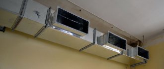
Heat load calculation
diagram of the heat load from general ventilation.
Calculation of the heat load on ventilation is carried out using the formula:
Q in = V n * k * p * C r ( t in - t nro),
in the formula for calculating the heat load on ventilation, Vn is the external volume of the building in cubic meters, k is the air exchange rate, tin is the average temperature in the building, in degrees Celsius, tnro is the outside air temperature used in heating calculations, in degrees Celsius, p is the air density , in kg\cubic meter, Ср - heat capacity of air, in kJ\cubic meter Celsius.
If the air temperature is below tnro , the air exchange rate decreases, and the heat consumption indicator is considered equal to Qв , a constant value.
If, when calculating the heat load for ventilation, it is impossible to reduce the air exchange rate, the heat consumption is calculated based on the heating temperature.
Heat consumption for ventilation
The specific annual heat consumption for ventilation is calculated as follows:
Q= * b * (1-E),
in the formula for calculating heat consumption for ventilation Qo is the total heat loss of the building during the heating season, Qb is domestic heat input, Qs is heat input from outside (sun), n is the coefficient of thermal inertia of walls and ceilings, E is the reduction factor. For individual heating systems 0.15 , for central heating systems 0.1 , b - heat loss coefficient:
- 1,11 — for tower buildings;
- 1,13 — for multi-section and multi-entry buildings;
- 1,07 - for buildings with warm attics and basements.
How to calculate the pressure in the ventilation network
In order to determine the expected pressure for each individual area, you must use the formula below:
Н x g (РН – РВ) = DPE.
Now let's try to figure out what each of these abbreviations means. So:
- H in this case denotes the difference in the elevations of the mine mouth and the intake grid;
- RV and RN are an indicator of gas density, both outside and inside the ventilation network, respectively (measured in kilograms per cubic meter);
- Finally, DPE is an indicator of what the natural available pressure should be.
We continue to analyze the aerodynamic calculation of air ducts. To determine the internal and external density, it is necessary to use a reference table, and the temperature indicator inside/outside must also be taken into account. As a rule, the standard outside temperature is taken as plus 5 degrees, regardless of in which specific region of the country construction work is planned. And if the temperature outside is lower, then as a result the injection into the ventilation system will increase, which, in turn, will cause the volumes of incoming air masses to be exceeded. And if the outside temperature, on the contrary, is higher, then the pressure in the line will decrease because of this, although this trouble, by the way, can be compensated for by opening the vents/windows.
As for the main task of any described calculation, it is to select such air ducts where losses on sections (we are talking about the value? (R*l*?+Z)) will be lower than the current DPE indicator or, as an option, at least equal to him. For greater clarity, we present the point described above in the form of a small formula:
DPE? ?(R*l*?+Z).
Now let’s take a closer look at what the abbreviations used in this formula mean. Let's start from the end:
- Z in this case is an indicator indicating a decrease in air speed due to local resistance;
- ? – this is the value, more precisely, the coefficient of the roughness of the walls in the pipeline;
- l is another simple value that indicates the length of the selected section (measured in meters);
- Finally, R is the friction loss index (measured in pascals per meter).
Well, we’ve sorted that out, now let’s find out a little more about the roughness index (that is?). This indicator depends only on what materials were used in the manufacture of the channels. It is worth noting that the speed of air movement can also be different, so this indicator should also be taken into account.
Speed – 0.4 meters per second
In this case, the roughness indicator will be as follows:
- for plaster using reinforcing mesh – 1.48;
- for slag gypsum - about 1.08;
- for ordinary brick - 1.25;
- and for slag concrete, respectively, 1.11.
Speed – 0.8 meters per second
Here the described indicators will look like this:
- for plaster using reinforcing mesh – 1.69;
- for slag gypsum – 1.13;
- for ordinary brick – 1.40;
- finally, for slag concrete – 1.19.
Let's slightly increase the speed of the air masses.
Speed – 1.20 meters per second
For this value, the roughness indicators will be as follows:
- for plaster using reinforcing mesh – 1.84;
- for slag gypsum – 1.18;
- for ordinary brick - 1.50;
- and, therefore, for slag concrete it is about 1.31.
And the last indicator of speed.
Speed – 1.60 meters per second
Here the situation will look like this:
- for plaster using reinforcing mesh, the roughness will be 1.95;
- for slag gypsum – 1.22;
- for ordinary brick – 1.58;
- and, finally, for slag concrete - 1.31.
Note! We have sorted out the roughness, but it is worth noting one more important point: it is advisable to take into account a small margin, fluctuating between ten and fifteen percent.
Calculation of the diameter of air ducts
air ducts of various diameters and cross-sectional shapes
The diameters and cross-sections of ventilation air ducts are calculated after the general diagram of the system has been drawn up. When calculating the diameters of ventilation air ducts, the following indicators are taken into account:
- The volume of air (supply or exhaust) that must pass through the pipe in a given period of time, cubic meters per hour;
- Air speed. If, when calculating ventilation pipes, the flow rate is underestimated, air ducts with a cross-section that are too large will be installed, which entails additional costs. Excessive speed leads to vibrations, increased aerodynamic noise and increased equipment power. The speed of movement on the tributary is 1.5 - 8 m/sec, it varies depending on the area;
- Ventilation pipe material. When calculating the diameter, this indicator affects the wall resistance. For example, black steel with rough walls has the highest resistance. Therefore, the calculated diameter of the ventilation duct will have to be slightly increased compared to the standards for plastic or stainless steel.
| Type of site | Flow speed, m/s |
| Main pipelines | From 6 to 8 |
| Lateral layers | From 4 to 5 |
| Distribution pipelines | From 1.5 to 2 |
| Upper inlets | From 1 to 3 |
| Hoods | From 1.5 to 3 |
Table 1 . Optimal air flow speed in ventilation pipes.
When the throughput of future air ducts is known, the cross-section of the ventilation duct can be calculated:
S = R \3600 v ,
here v is the speed of the air flow, in m/s, R is the air flow rate, cubic meters/hour.
The number 3600 is the time coefficient.
Knowing the cross-sectional area, you can calculate the diameter of the round ventilation duct:
here: D is the diameter of the ventilation pipe, m.
If it is necessary to calculate the diameter of a rectangular ventilation pipe, its parameters are selected based on the obtained cross-sectional area of the round pipe.
Calculation of the area of ventilation elements
Calculation of the ventilation area is necessary when the elements are made of sheet metal and it is necessary to determine the quantity and cost of the material.
The ventilation area is calculated using electronic calculators or special programs; many of them can be found on the Internet.
We will provide several tabular values of the most popular ventilation elements.
| Diameter, mm | Length, m | |||
| 1 | 1,5 | 2 | 2,5 | |
| 100 | 0,3 | 0,5 | 0,6 | 0,8 |
| 125 | 0,4 | 0,6 | 0,8 | 1 |
| 160 | 0,5 | 0,8 | 1 | 1,3 |
| 200 | 0,6 | 0,9 | 1,3 | 1,6 |
| 250 | 0,8 | 1,2 | 1,6 | 2 |
| 280 | 0,9 | 1,3 | 1,8 | 2,2 |
| 315 | 1 | 1,5 | 2 | 2,5 |
Table 2 . Area of straight round air ducts.
Area value in sq. m. at the intersection of horizontal and vertical stitching.
| Diameter, mm | Angle, degrees | ||||
| 15 | 30 | 45 | 60 | 90 | |
| 100 | 0,04 | 0,05 | 0,06 | 0,06 | 0,08 |
| 125 | 0,05 | 0,06 | 0,08 | 0,09 | 0,12 |
| 160 | 0,07 | 0,09 | 0,11 | 0,13 | 0,18 |
| 200 | 0,1 | 0,13 | 0,16 | 0,19 | 0,26 |
| 250 | 0,13 | 0,18 | 0,23 | 0,28 | 0,39 |
| 280 | 0,15 | 0,22 | 0,28 | 0,35 | 0,47 |
| 315 | 0,18 | 0,26 | 0,34 | 0,42 | 0,59 |
Table 3 . Calculation of the area of bends and half-bends of circular cross-section.
Rules for using measuring devices
When measuring air flow speed and its consumption in a ventilation and air conditioning system, you need to correctly select devices and comply with the following rules for their operation.
This will allow you to obtain accurate results of air duct calculations, as well as create an objective picture of the ventilation system.
In order to record average flow rates, you need to take several measurements. Their number depends on the diameter of the pipe or on the size of the sides if the channel is rectangular in shape
Observe the temperature regime indicated in the device passport. Also monitor the position of the probe sensor. It must always be oriented exactly towards the air flow.
If this rule is not followed, the measurement results will be distorted. The greater the deviation of the sensor from the ideal position, the higher the error will be.
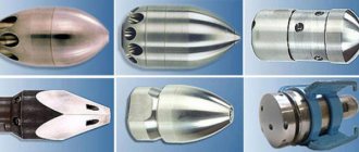
Calculation of diffusers and grilles
diffuser in industrial ventilation
Diffusers are used to supply or remove air from a room. The cleanliness and temperature of the air in every corner of the room depends on the correct calculation of the number and location of ventilation diffusers. If you install more diffusers, the pressure in the system will increase and the speed will drop.
The number of ventilation diffusers is calculated as follows:
N = R \(2820 * v * D * D ),
here R is the throughput, in cubic meters per hour, v is the air speed, m per second, D is the diameter of one diffuser in meters.
The number of ventilation grilles can be calculated using the formula:
N = R \(3600 * v * S ),
here R is the air flow in cubic meters per hour, v is the air speed in the system, m per second, S is the cross-sectional area of one grille, sq.m.
Consequences of poor ventilation
If the fresh air supply system is not properly organized, the rooms will experience a lack of oxygen and increased humidity. Errors in the design of the hood are fraught with the appearance of soot on the walls of the kitchen, fogging of the windows and the appearance of fungus on the surface of the walls.
Fogging of windows due to insufficient exhaust
It should be taken into account that round or square pipes can be used to install the ventilation system. When removing air without the use of special devices, it is advisable to install round air ducts, since they are stronger, more airtight and have good aerodynamic characteristics. Square pipes are best used for forced ventilation.
Calculation of a duct heater
electric duct heater
Calculation of an electric type ventilation heater is carried out as follows:
P = v * 0.36 * ∆ T
here v is the volume of air passed through the heater in cubic meters per hour, ∆T is the difference between the air temperature outside and inside, which must be provided to the heater.
This indicator varies between 10 - 20, the exact figure is set by the client.
Calculation of a heater for ventilation begins with calculating the frontal cross-sectional area:
Af = R * p \3600 * Vp ,
here R is the volume of inlet flow, cubic meters per hour, p is the density of atmospheric air, kg per cubic metre, Vp is the mass air velocity in the area.
The cross-sectional size is necessary to determine the dimensions of the ventilation heater. If, according to calculations, the cross-sectional area turns out to be too large, it is necessary to consider the option of a cascade of heat exchangers with a total calculated area.
The mass velocity indicator is determined through the frontal area of the heat exchangers:
Vp = R * p \3600 * A f.fact
To further calculate the ventilation heater, we determine the amount of heat required to warm the air flow:
Q =0.278 * W * c ( T p - T y),
here W is the flow of warm air, kg/hour, Тп is the temperature of the supply air, degrees Celsius, Тu is the temperature of the street air, degrees Celsius, c is the specific heat capacity of the air, a constant value of 1.005.
Since fans in supply systems are placed in front of the heat exchanger, we calculate the flow of warm air as follows:
W = R*p
When calculating the ventilation heater, you should determine the heating surface:
Apn=1.2 Q \ k ( T s.t - T s.v),
here k is the heat transfer coefficient of the heater, Tс.т is the average temperature of the coolant, in degrees Celsius, Tс.в is the average inlet temperature, 1.2 is the cooling coefficient.
How to determine the speed in ventilation ducts?
As can be judged from everything said above, as the main highway it is necessary to choose the chain of successive sections of the network that is the longest; in this case, the numbering should begin exclusively from the most remote section. As for the parameters of each section (and these include air flow, section length, its serial number, etc.), they should also be entered into the calculation table. Then, when the application is completed, the shape of the cross-section is selected and its cross-sections and dimensions are determined.
LP/VT = FP.
What do these abbreviations stand for? Let's try to figure it out. So, in our formula:
- LP is the specific air flow rate in the selected area;
- VT is the speed at which air masses move through this area (measured in meters per second);
- FP is the cross-sectional area of the channel we need.
Typically, when determining the speed of movement, it is necessary to be guided, first of all, by considerations of economy and noise level of the entire ventilation network.
Note! Based on the indicator obtained in this way (we are talking about the cross section), it is necessary to select an air duct with standard values, and its actual cross-section (denoted by the abbreviation FF) should be as close as possible to the previously calculated one.
LP/ FF = VФ.
Having received the required speed indicator, it is necessary to calculate how much the pressure in the system will decrease due to friction against the walls of the channels (for this you need to use a special table). As for the local resistance for each section, they should be calculated separately and then summed up into a common indicator. Then, by summing up the local resistance and losses due to friction, the total losses in the air conditioning system can be obtained. In the future, this value will be used to calculate the required amount of gas masses in the ventilation channels.
Air heating unit
Previously, we talked about what an air heating unit is, talked about its advantages and areas of application, in addition to this article, we advise you to read this information
Advantages and disadvantages of plastic ventilation pipes for hoods
Without a doubt, flat plastic air ducts are very popular for use in residential non-industrial premises. Here we should highlight the following positive properties of such products:
- Due to the absence of elements susceptible to oxidation, plastic wires do not suffer from corrosion. This feature greatly simplified the work of designers, eliminating the need to provide additional protection systems. Oxidation resistance makes the structure itself and the process of its installation simpler;
- cost reduction: PVC ventilation pipes are significantly (sometimes 2-3 times) cheaper than their metal counterparts;
- the smooth inner surface promotes maximum air flow and does not require periodic cleaning;
- the ability to cut parts of the wire at the installation site, and a wide range of different fittings greatly simplify the assembly and installation of the structure;
- non-toxic and completely safe for both humans and the environment.8.
Along with all the listed advantages, flexible PVC air ducts also have one significant drawback: low fire resistance.
Installing a hood in the kitchen: is it possible to do without it?
It is not always possible to install a hood in the kitchen. There are cases when its installation is prohibited according to the rules for operating gas appliances. For example, if a gas water heater, the so-called gas water heater, or a gas heating boiler with an open combustion chamber is installed in the room, it is contraindicated to install a circulation hood.
In most cases, it is impossible to do without a hood.
On a note! Removal of decomposition products from the boiler occurs without force, and when the fan on the hood is turned on, the draft may overturn, which will lead to the release of toxic combustion products into the apartment. Therefore, installation of a flow-through exhaust device is allowed only if the boiler is installed with a closed firebox, that is, with a coaxial type chimney and combustion air intake from the street. It is possible to install a circulation hood with filters that clean the air from grease and fumes.
Therefore, before making a hood in the kitchen, you need to figure out whether it is possible to do without an air duct. If you still need it, then you should decide on the type of device. Hoods can be flow-through or circulating. Flow-type devices extract exhaust air from the kitchen, while circulation devices simply purify the air without eliminating it.
Circulation devices are installed above the stove, the air passes through special carbon filters, and grease is removed there. Such designs do not require air ducts; they are compact and easy to install. The main disadvantages of a hood without an air duct are the need to frequently change filters, incomplete air purification, and the lack of removal of humidity and carbon dioxide.