Thermostatic valve (TRV) is one of the elements without which the operation of the refrigeration circuit is impossible. In other words, without a expansion valve, not a single refrigeration machine will be able to function. Instead of an expansion valve, another device with similar functional properties can also be installed in the refrigeration circuit. This may be a simpler and cheaper capillary tube, or a more expensive and complex electronic expansion valve (ETV). All these devices have one common name - throttling devices. The installation of one or another throttling device in the refrigeration circuit is regulated only by the manufacturer, based on the characteristics of a particular type of air conditioner.
Automatic baroregulating valves
Automatic barostatic valves are the predecessors of thermostatic valves. They regulate the flow of refrigerant into the evaporator, ensuring constant pressure in the evaporator itself. They can only be used in installations with a constant loading mode.
The valve calibration can be adjusted over a certain range of values depending on operating conditions.
The circuit must have an evaporator thermostat that stops the compressor when the required evaporation temperature is reached (not to be confused with room temperature). More precisely, it must be adjusted so that the response temperature is approximately 5°C higher than the evaporation temperature. When the compressor stops, pressure rises and the automatic expansion valve closes. Figure 14.1 shows a schematic diagram of a refrigeration circuit in which an automatic expansion valve is installed.
| Figure 14.1. An example of installing an automatic expansion valve in a refrigeration group for a small refrigerator. |
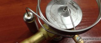
Features of Danfoss, Eagle products
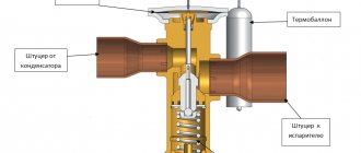
The Danfoss thermostatic valve differs in its design and other features from other valves. In terms of design, this device includes a thermostat, which is separated from the valve itself by a membrane. In addition, one of the important elements of these valves is the spring. It carries out the process of regulating superheat.
If we talk about the products of the Eagle company, we can highlight the following regulator. Radiator thermostatic valve Eagle 302-1608. It has internal as well as external threads. It is characterized by pressure such as 1.6 MPa or 16 kgf/cm2. The type of this regulator is direct.
All Danfoss products are divided into several categories:
- TE5-TE55. These devices are intended to regulate the flow of liquid refrigerant into evaporative devices installed in refrigeration units.
- TGE. This group of products is distinguished by the fact that the design of the valve units of the device is irreplaceable, and they were manufactured specifically for the air conditioner. The thermostatic valve of this category is intended for commercial air conditioning systems, which are characterized by high power.
Thermostatic valves (TRV)
Thermostatic expansion valves regulate the flow of refrigerant into the evaporator depending on a certain superheat value of the refrigerant gas leaving the evaporator. The evaporator receives the required amount of refrigerant to evaporate it, depending on the heat load, to ensure full use of the heat exchange surface area. TRVs can be used on lines with one or more evaporators.
Figure 14.2 shows a schematic diagram of the refrigeration circuit in which the expansion valve is installed.
| Figure 14.2. An example of installing a expansion valve in a refrigeration circuit for an autonomous air conditioner with a water-cooled condenser |
Depending on the pressure indicator, two main modifications are used:
- Internal pressure equalization
- External pressure equalization in the expansion valve
Internal pressure equalization
Figure 14.3 shows the operating diagram and pressure vectors acting on expansion valves with internal pressure equalization. The valve membrane is affected on one side by the pressure transmitted from the sensor (p), and on the opposite side by the sum of the evaporator pressures (p0) and the pressure spring (p3). When these three pressure vectors are equalized, the valve remains constantly open, and, accordingly, the flow of refrigerant passing through it remains constant. Under these conditions, the amount of refrigerant entering the evaporator exactly corresponds to that required to absorb the thermal load. If the load decreases, two processes occur: there is an excess amount of refrigerant, and its pressure increases; the gas temperature at the outlet decreases and the pressure in the sensor decreases in proportion to this. As a result of these processes, the sum of the evaporator and spring pressures exceeds the pressure exerted on the valve sensor, which leads to the closing of the valve with a decrease in the clearance for the passage of refrigerant. On the contrary, if the heat load in the evaporator increases, the amount of refrigerant in it is insufficient, and its pressure decreases; at the same time, the gas temperature at the outlet of the evaporator increases, which causes a corresponding increase in pressure on the valve sensor.
As a result, the pressure in the valve moves the membrane down, which opens the gap for the passage of liquid refrigerant, increasing the volume of its flow into the evaporator.
Valves with internal pressure equalization are mainly used in low-power installations.
| Figure 14.3. Operating principle of expansion valve with internal pressure equalization. |
External pressure equalization in the expansion valve
The expansion valves with external pressure equalization have a pressure supply from the evaporator through a corresponding line (capillary tube), which extends from it slightly below the valve sensor. The corresponding diagram is shown in Figure 14.4. All previously mentioned provisions remain valid, except that the pressure p0 in the evaporator is determined using a capillary tube.
Expansion valves with external pressure equalization are usually used on medium and large power units.
| Figure 14.4. Operating principle of expansion valve with external pressure equalization. At the top you can see the entrance of the capillary tube from the alignment line below the valve accordion. The meaning of the symbols is the same as in Figure 14.3. |
Figure 14.5 shows a diagram of the correct valve installation with the appropriate external pressure equalization line; For comparison, Figure 14.6 shows an incorrect placement of components: the equalization line pressure outlet should always be located slightly below the valve sensor on the top side of the horizontal tube.
| Figure 14.5. Correct installation of the expansion valve. The equalization channel outlet is located before the valve sensor. |
| Figure 14.6. Incorrect installation of the expansion valve. The pressure channel outlet is made on the lower side of the tube. |
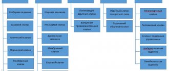
Existing types of TVR in air conditioning:
- with internal and external alignment - classic design with a thermocylinder, capillary tube and membrane;
- with a block structure, so-called H-shaped valves - elements that respond to fluctuations in temperature and pressure are built into the valve, eliminating the possibility of damage to the thermal cylinder;
- with the installation of a gas thermal head - the reacting elements are installed inside the thermal heads, adjustment is made according to the set temperature level or through the air conditioner TRV sensor with electronic regulation.
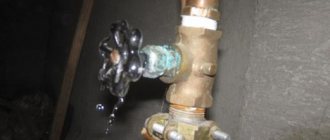
Typical causes of failure of the expansion valve:
- mechanical damage to the thermal cylinder, capillary tube and other parts of the unit with associated refrigerant leakage;
- entry of dirt, metal particles and water into the system;
- errors when choosing a device modification, configuration and installation - insufficient contact between the thermal balloon and the outlet tube, which does not allow the temperature of the refrigerant to be perceived.
Is it necessary to replace the air conditioner's expansion valve?
If the diagnostics conclude that the valve is faulty, it must be replaced. You need to buy a TRV air conditioner of the modification that matches the installed equipment. An error can lead to financial losses and complete system failure.
Replacing the valve of household and industrial climate control devices, as well as the expansion valve of a vehicle air conditioner, must be performed by qualified specialists with the necessary equipment and devices. Otherwise, there are no guarantees of high-quality work.
Gas outlet overheating
The thermostatic valve provides a certain superheat of the gas at the outlet of the evaporator, which is necessary for the complete evaporation of possible drops of the carrier liquid (liquid refrigerant should not be returned to the compressor under any circumstances, as it can cause serious malfunctions). Figure 14.7 shows part of the evaporator under normal operating conditions. As you can see, the liquid-vapor mixture entering the evaporator at point A must completely evaporate before point E.
From here to the valve sensor (point F), only gas overheating occurs. Overheating consists of increasing the temperature of the gas above its saturation temperature (see below). This area, that is, the additional surface of the evaporator, does not increase the refrigeration effect, but serves to protect the compressor and ensure stable operation of the valve.
| Figure 14.7. Diagram of the part of the evaporator in which the expansion valve with internal pressure equalization is installed: the section from E to F does not produce a useful refrigeration effect, but serves solely to impart a certain superheat to the gas at the outlet. The meaning of the symbols is the same as in Figure 14.3. |
Tips on how to choose
Popular manufacturers
Leading positions in the production of thermostatic valves for heating systems belong to Danish manufacturers. The first and second places are occupied by Danfoss and Broen. In third place is the German brand Oventrop. Products from Heimeir, Herz, Honeywell, MNG, Schlosser, and Valtec are also in high demand on the domestic market.
What does the cost depend on and what is the approximate price?
How much a valve costs primarily determines the type of thermostatic device. Manual valves are cheaper than automatic valves. Thermostatic fittings with an electronic control unit are the most expensive, but they are an integral part of a modern smart home. The price, depending on the brand, ranges from 1000 rubles. for Valtec valves up to RUB 3,000. to devices from the Danish manufacturer Danfoss.
Performance
The performance of a thermostatic expansion valve is determined by two components:
- liquid passage, that is, the mass of liquid refrigerant capable of passing through the valve per unit time;
- refrigeration effect, that is, the amount of heat that can accumulate the refrigerant from the evaporator.
The performance of the expansion valve and, as a result, the passage of liquid and the refrigeration effect are influenced by the following factors:
- pressure drop across the valve;
- refrigerant condition;
- hypothermia;
- valve calibration;
- evaporation temperature;
- thermostatic load.
Valve pressure drop
The refrigerant pressure decreases rapidly as it passes through the valve, causing some to evaporate quickly, preventing the passage of another batch of liquid (Figure 14.8).
The higher the pressure drop through the valve, the greater the amount of steam generated, the presence of which prevents the increase in flow, which increases with increasing pressure difference.
If the pressure drop is large as refrigerant passes through the valve, the refrigeration effect is reduced because more liquid refrigerant evaporates.
| Figure 14.8. Passage of refrigerant through the expansion valve: the rapid evaporation of liquid to form steam makes it somewhat difficult for a new batch of liquid to pass through. |
| Figure 14.9. The performance characteristic of a thermostatic valve: as the pressure on the valve increases, its performance increases, but only up to a certain limit, after which the performance begins to decrease. |
Increasing the pressure drop across the valve increases its performance up to a certain limit, after which any increase in pressure drop begins to reduce performance (see Figure 14.9). The limit value of the pressure difference, after which the valve performance begins to decrease, depends on the type of refrigerant.
Refrigerant status
The presence of steam at the inlet to the valve leads to a decrease in its performance, since steam, with equal weight, occupies a larger volume than liquid, with a consequent reduction in the volume of liquid passage.
The presence of steam can be caused either by the lack of refrigerant in the circuit or by a high pressure drop, due to which the pressure at the valve inlet is maintained at a significantly lower pressure than the pressure in the condenser. Another reason may be a strong difference in height between the condenser and the expansion valve, in which case the liquid subcooling method is used.
Hypothermia
Subcooling of the liquid refrigerant also increases the performance of the expansion valve due to the following reasons:
- when overcooled, the volume of liquid that evaporates when passing through the valve decreases, leading to an increase in its permeability;
- since less liquid evaporates, more of it can still evaporate; ultimately there is an increase in the refrigeration effect.
Overheat
Figure 14.10 shows the curve corresponding to the change in valve performance when the superheat parameter changes.
| Figure 14.10. Change in the performance of the expansion valve relative to the change in the superheat indicator: in this example, as in the previous one, the performance increases with increasing superheat, but only up to a certain limit. |
This process, depending on the valve model and its performance, can be divided into the following steps:
- Static overheating. We are talking about the value of the superheat indicator necessary to compensate for the spring pressure in such a way that with a further increase in temperature the valve opens.
- Overheating of valve opening. This is the value of the superheat indicator at which the valve needle moves from its seat, opening the passage for liquid.
- Real overheating of the installation. Is the sum of static overheat and valve opening overheat; this is a real indicator of superheat at which the valve will operate.
The superheat value of the installation is derived based on the difference between the evaporation temperature and the temperature of the cooled liquid: when this difference is small, the best way to rationally use the evaporator is to select a low superheat temperature; with a significant temperature difference, it is necessary to provide protection against possible liquid returns, increasing the overheating temperature for this purpose.
If the thermostatic valve is selected correctly, it should not open completely when operating at rated power; Thus, the expansion valve will have a certain capacity reserve, which will be used only at high superheat values.
TRV calibration
When the adjusting rod is rotated clockwise, the spring pressure increases, which corresponds to an increase in static superheat and a decrease in valve performance.
Evaporation temperature
The pressure-temperature curves of all refrigerants at a given temperature increase have more noticeable pressure fluctuations in the high-temperature section. As a consequence, at low evaporation temperatures, a small change in temperature at the valve sensor results in small pressure fluctuations on the upper side of the diaphragm: this results in less valve opening and smaller changes in its permeability.
Thermostatic charge
The pressure-temperature indicators of various thermostatic charges have their own distinctive features: with the same superheat indicator, the valve does not open the same when the type of charge changes.
Design and principle of operation
Thermostatic valves differ in design and operating principle depending on the type. A manual valve has a body with a stem and a spool that acts on the seat in the flow section. When the rod is turned clockwise, the flow area decreases; when rotated in the other direction, it increases. As a result, the coolant flow passing to the heating device per unit time changes.
Inside the body of the automatic temperature control valve there is a thermal head with a thermal cylinder filled with kerosene, gas or a special liquid. When heated, the substances in the thermal head expand and change their physical state. The thermal balloon stretches, acts on the rod and causes it to move and be squeezed out of the bellows. The flow area is closed, and when the surrounding air cools, it opens again when the thermal cylinder returns to its original position.
Operation under load changes
In various types of high-capacity refrigeration and air-conditioning units with multiple compressors, it is possible to reduce the refrigeration capacity as the load decreases by progressively switching off the running compressors and/or their individual cylinders. Unfortunately, the performance of the expansion valve cannot be changed as easily, therefore, when the compressors are stopped or partially deactivated, the valve capacity becomes excessive. The valve can be adjusted within reasonable limits and is still able to provide the required refrigerant flow. It is also clear that when operating at low loads, careful adjustment of the valve is not required, since not the entire evaporator is used, and there is no danger of liquid returning. It is difficult to foresee in advance the operating mode of the expansion valve when the system is operating at a reduced mode due to the many factors affecting its operation. The following is a list of precautions that, if observed, will ensure normal valve operation even when the load is reduced to 65%.
The expansion valve should be selected in such a way that at maximum loads it remains as open as possible. In particular, when the planned operation involves primarily reduced load operation, it is recommended to select a valve with a capacity 10-15% less than the maximum operating parameters of the installation.
Chiller operating principle
Rankine cycle Carnot cycle
evaporation
An industrial chiller consists of three main elements: a compressor, a condenser and an evaporator. The main task of the evaporator is to remove heat from the object being cooled. For this purpose, water and refrigerant are passed through it. As the refrigerant boils, it takes energy away from the liquid. As a result, water or any other coolant is cooled, and the refrigerant is heated and goes into a gaseous state. After this, the gaseous refrigerant enters the compressor, where it acts on the compressor motor windings, helping to cool them. There, the hot steam is compressed, again heating up to a temperature of 80-90 ºС. Here it is mixed with oil from the compressor.
In the heated state, freon enters the condenser, where the heated refrigerant is cooled by a flow of cold air. Then the final cycle of work begins: the refrigerant from the heat exchanger enters the subcooler, where its temperature decreases, as a result of which the freon turns into a liquid state and is supplied to the filter drier. There it gets rid of moisture. The next point on the path of refrigerant movement is the thermal expansion valve, in which the freon pressure decreases. After leaving the thermal expander, the refrigerant is low pressure steam combined with liquid. This mixture is fed to the evaporator, where the refrigerant boils again, turning into steam and superheating. The superheated steam leaves the evaporator, which is the beginning of a new cycle.
Superheat calibration
Calibration of the superheat value should ensure the highest superheat value permissible at maximum load.
In an installation where the partial load reduction exceeds 65% of its capacity, the other measures listed below must be applied.
Two or more evaporators with the same parameters
Figure 14.11 shows two independent evaporators, each supplied by its own expansion valve with distributor. Each evaporator accounts for half of the total load.
| Figure 14.11 Independent power supply of two parallel evaporators of equal power, the operation of each of which is regulated by its own expansion valve and distributor: please note that the first section of the suction line is slightly inclined towards the siphon, which is done to prevent sedimentation of refrigerant and oil, distorting the sensor readings expansion valves. |
The solenoid valves are connected to a device to reduce the compressor capacity in such a way that one of them closes when the load on the compressor is reduced by 50%, cutting off one of the thermostatic valves. The remaining expansion valve ensures that performance is maintained at the required level.
The same simple system is applicable to different evaporators at different levels of compressor partial reduction. Different types of compressors can be connected in parallel or in series; In this case, it must be taken into account that the compressors located first will experience a higher load than those that follow, so the performance of the various valves and distributors must be adjusted to take this into account.
Single evaporator
Figure 14.12 shows a diagram of the installation of two expansion valves and two distributors on one evaporator.
| Figure 14.12. Single evaporator with two independent circuits, controlled by two solenoid valves, expansion valves and distributors. When the cooling load decreases, one of the solenoid valves closes, allowing a partial reduction in the generated cooling power. |
Each evaporator circuit has a supply of two distribution tubes, each of which, in turn, passes through its own distributor. The solenoid valves are controlled by the compressor partial load control device as previously described.
If the expansion valve, solenoid valve and distributor of circuit A are selected to cover 67% of the total capacity and 33% of the total maximum load is on circuit B, the switching of the solenoid valves will provide the operating parameters shown in Table 14.1.
Table 14.1. Switching sequence of solenoid valves when the thermal load changes.
| Thermal load (%) | Valve A | Valve B | Use of installed expansion valves (%) |
| 100 83 | Open | Open | 100 83 |
| 67 50 | Closed | 100 75 | |
| 33 16 | Closed | Open | 100 50 |
Manufacturers and cost
It is logical that the cost of the product is formed not only from those characteristics that were listed above. This parameter also varies depending on which manufacturer produced a particular valve. Currently, there are several companies whose products are considered the best on the market:
- The first representative is the German company Oventrop. The main advantage of their product is, of course, high quality. The price of a thermostatic valve from this manufacturer starts from 1,000 rubles.
- The second well-known manufacturing company is Danfoss. The company is Danish, and the cost of their products starts from 1,500 rubles. A distinctive feature of their product is that they use the latest technologies for production, which increases the service life of the valve.
- The last of the three well-known representatives was the Italian company Luxor, which stands out from the rest with its prices - from 250 rubles, and is also characterized by the fact that the products from the manufacturer are quite reliable.
Maintenance and installation
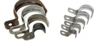
The thermostatic valve should be installed as close as possible to the evaporator inlet. If a distributor is used, it is recommended to install it directly at the outlet of the expansion valve. It is very important to ensure the correct location of the thermal cylinder, which in some cases determines the good or unsatisfactory operation of the entire refrigeration system. In order for the valve to properly regulate the flow of refrigerant, it is necessary to ensure good thermal contact between the thermal bulb and the suction pipe. To do this, the thermal cylinder should be secured with two brackets on a clean and level section of the pipe. It is recommended to install the sensor element on a horizontal section of the suction pipe. If vertical installation cannot be avoided, this must be done in such a way that the outlet of the capillary tube is directed upwards.
| Figure 14.13. Examples of possible installation of a thermal cylinder on a pipe with a diameter of 22 mm or more. |
| Figure 14.14. Location of the suction line at the outlet of the evaporator battery. There are two possible compressor location options: under the evaporator (solid line) and above the evaporator (dashed line). |
With a suction line diameter of 7/8″ (22 mm) or larger, the temperature around the perimeter of the pipe circumference may vary markedly. In this regard, the thermal bulb should be placed at the point on the pipe circumference corresponding to the 16 and 20 o'clock positions on the watch dial (see Figure 14.13). When the compressor is located above the evaporator, it is recommended to connect the suction line as shown in Figure 14.14. At the outlet of the evaporator there should be a horizontal section of pipe on which the thermal cylinder is attached; a storage siphon must be installed immediately behind it to collect any liquid that may be present and any oil that may be present circulating through the installation.
Installations with multiple evaporators
When the compressor is located below the evaporator, it is necessary to install a reservoir above the evaporator to prevent liquid gravity returning to the compressor. In installations with multiple evaporators, the suction pipes must be positioned in such a way as to prevent one expansion valve from affecting the sensor of another. An example of correct pipe placement is shown in Figure 14.15. In this case, the influence of one circuit on another is not allowed and a good mode of operation and adjustment of each expansion valve is ensured.
| Figure 14.15. Diagram of the location of suction lines and the position of the expansion valve on installations with several interconnected evaporators on one manifold; the slope of the latter should not be less than 1%. |
Connecting an external pressure equalization device
Valves with external pressure equalization can only function if this connection is provided. The connection fitting of the pressure equalization device (equalizer) should be located on the suction pipe a few centimeters after the thermal bulb, as already shown in Figure 14.12.
Valve adjustment
Each expansion valve is calibrated at the factory before delivery. This calibration is correct and in most cases does not require readjustment. However, under special conditions or certain types of valve applications, the valve calibration may be changed to achieve the desired superheat ratings.
Many types of expansion valves do not have the possibility of adjustment: they are calibrated at the manufacturer, and their overheating indicator cannot be changed. Often non-adjustable valves are modifications of conventional valves with a fixed spring pressure. There are devices that allow you to adjust these types of valves, but such a need rarely arises.
If you need to reduce the superheat value, you should rotate the valve adjustment rod counterclockwise, to increase it - clockwise. When changing the valve calibration, to prevent calibration errors, it is recommended not to make more than one turn of the adjustment rod at a time and to wait at least thirty minutes before making another adjustment.
The general rule is that the amount of superheat depends on the temperature difference between the evaporator and the cooled substance. For very large temperature differences, as in the case of air conditioning units, superheating can reach 10°C without unduly reducing evaporator performance. For low temperature refrigeration applications, where the difference between the evaporation temperature and the temperature of the cooled substance is negligible, the superheat value can be reduced to 5°C in order to maximize the use of the evaporator surface area.
Determination of superheat value
It is possible to determine the amount of overheating by performing the operations listed below. The difference between the temperature at the evaporator inlet and the temperature at the outlet of the evaporator does not allow obtaining an accurate superheat value, therefore this method is not recommended, since the pressure drop in the evaporator leads to errors in determining the superheat value.
- Measure the suction temperature at the location where the thermal cylinder is installed.
- Measure the pressure at the compressor suction valve with a pressure gauge.
- From the pressure value obtained above, the saturation temperature is determined using a table of the relationship between temperature and pressure of the refrigerant (in most cases, pressure losses in the suction pipe can be neglected due to their smallness).
- Subtract the temperature value in point 3 from the temperature value in point 1. The resulting difference is the superheat temperature.
Structure and principle of operation of the cooling system
To understand the functions of a thermostatic valve, you must have at least a basic understanding of the operation of the refrigeration system. A refrigeration system can be defined as a closed loop, the process of absorbing and transferring heat by a refrigerant in a vapor compression cycle. In its simplest form, a refrigeration system includes five components:
- capacitor;
- compressor;
- evaporator;
- expansion device;
- connecting pipeline.
Thermostatic valve design diagram
The heart of the refrigeration system is the compressor, as it circulates the refrigerant. Its role is to suck low temperature (and pressure) vapors from the evaporator and compress them to high temperature (and pressure). After this, the high-temperature vapors pass into the liquid phase in the condenser. The condenser does this work by removing heat from high-temperature vapors into the atmosphere or, if the condenser is water-based, by removing heat to water. The liquid remaining at high temperature enters expansion devices and turns into a two-phase mixture (steam and liquid) at low temperature. In the evaporator, this mixture returns to its original state by removing heat from the medium, which is cooled.
The correct choice of expansion valve is very important, since it regulates the degree of filling of the evaporator. Incorrectly selected or used expansion devices will complicate control and cause poor performance of the entire system. For example, an expansion device that is insufficient in performance will cause the design output of the entire system. An expansion device that is too large may allow too much liquid into the evaporator, causing liquid droplets to enter the compressor suction. If the error is not corrected soon, the compressor may break down. Hence the conclusion is that expansion devices must be correctly selected and installed.