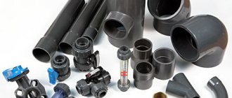
In essence, the valve is a shut-off and control pipeline fitting. This is a mechanical device used to pass, block or regulate the flow of liquids, vapors or gases through a pipeline. Based on the above, such a product can be called a periodic obstacle located inside the pipe. The valve sizes can be several centimeters or several millimeters. The exact parameter depends on the parameters of the pipe on which it is installed. The structure can be attached to the pipeline using threaded, flanged or welded connections.
Pipeline fittings have found wide application in various technological systems. By turning the tap fitted to the pipe coming from the stove, you can regulate the gas consumption, and the valve installed on the car tire makes it easier to inflate it with air, preventing air flows from escaping outside. A valve mounted inside the steam radiator makes it possible to bleed off the air there and replace it with steam.
Main details
Control valve design The
control valve design includes: a body, a cover (head), a seat, a gate (damper) and a rod (spindle) with a flywheel. Sometimes the flywheel can be replaced with an automatic attachment. All components are combined through the body. The working material is fed into the device through the body. The spindle located in the head (the sealing gland is also located here) causes the valve to move, as a result of which the hole in the seat opens or closes. The working staff, entering through it, comes out on the other side. The flow can be straight or curved.
Connection type
Depending on the type of connection to network pipes, control valves are:
- welded;
- flanged;
- fitting
- coupling;
- tsapkovymi.
Welded fittings (for welding) are produced only in a steel casing. This type of connection is the most reliable, but has a high execution price and is limited in maintainability. Used in industrial networks.
Flange products have found the widest application in all major highways with various environments.
In household communications, control valves are connected through threaded connections on couplings.
Materials for production
Cast iron valve
For the manufacture of such structures, materials are used that meet the necessary requirements set for a certain type of pipes and working compositions.
The valve can be manufactured using the following materials:
- cast iron for forging or foundry (gray);
- stainless or carbon steel;
- bronze;
- Inconel, Monel and other metals based on nickel.
The materials that are suitable for such production differ in price and degree of resistance to temperature changes and rust formation.
Gray cast iron, for example, is used in most cases to make low-grade fixtures. Bronze, due to its high resistance to corrosion, is used to work with corrosive materials. Carbon steel, as the most durable of the listed metals, is used where high pressure is maintained. Heat-resistant chromium-molybdenum material is used in industries where air temperatures can rise to 600°C.
Valves consisting of the above metals are used to equip urban hydraulic systems. Elements mounted inside the structure can be made of the same alloys as the body, or they can consist of plastic (most often used in gravity models) and rubber-containing materials.
To seal and improve the sealing of the seat, valve stem and valve, in most cases graphite, cotton, rubber or Teflon are used (it all depends on the type and temperature of the pipe contents, as well as on the conditions in which the device is used).
Purpose and scope of application
The need for flow regulation arises when monitoring technological processes of varying degrees of complexity and ensuring the stability of transient conditions.
Both representatives of control technology are used in gas, industrial and utility pipelines, sewerage pipes, and at such complex facilities as nuclear power plants and thermal power plants.
Structures of this type are widely used in domestic water supply and heating systems.
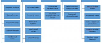
Types of valves
Gate valve
*
A linear movement gate design or gate valve (gate valve) is often used for pipelines. This type of industrial valve is called a gate valve. It can be completely closed or open. Open allows the flow of matter to pass through the pipeline almost unhindered.
The valve mechanism, when compared to a gate, significantly complicates the movement of the composition through the pipes. Pressure differences occurring across the valve are used to regulate the flow of matter or pressure inside the pipeline.
The valve mechanism is equipped with a rotating spindle. When the flywheel rotates, the spindle moves relative to the head threads. As a result, the shutter rises or lowers.
Needle valve
The needle device is small. The shape of the working area of the needle device rod resembles a cone, which allows you to regulate the flow of working matter without jerking.
Membrane type device
A diaphragm-type valve looks like a valve with a flexible diaphragm located on the spindle (between the body and the head). Under the influence of the rod, the membrane, moving, either regulates the current position of the mechanism or completely blocks it. The moving components of such a mechanism do not interact with the fluid flow, so the membrane does not need to replace the valve or sealing materials. The purpose of membrane devices is to interact with liquids that contain solid particles or are carriers of an aggressive environment.
Application of check valve
*
The purpose of the reverse mechanism is to prevent the reverse movement of liquid inside the pipeline. There are two main types of check valves known to exist. They can be folding or lifting. The former are equipped with a hinged valve mounted above the saddle. Under the influence of the flow coming from the side of the hole, the damper opens and the liquid freely penetrates through the valve. If the flow changes direction, the valve will lower and close the hole, pressing tightly against the seat under fluid pressure. The lifting sash operates on a similar principle, moving in a vertically located guide cylinder. When the flow changes direction, the valve will lower and press tightly against the seat.
Disc mechanism
Poppet valves are single-seated valves that open by means of “cams” and levers, and close due to the action of springs. Motorists use such devices to supply fuel and air to the cylinders and engine of the car, as well as to exhaust used gases. The described disc mechanism is installed in some types of steam engines and in steam turbines as a device for regulating the supply of steam.
Bellows device
The bellows valve has a corrugated structure made of metal materials. Such a product retains strength and tightness under repeated compression, stretching, and bending. It is used in pipeline fittings as a sealing, strength element.
Application of pulse devices
To protect against mechanical damage to pipelines due to excessive pressure, pulse valves are used. By automatically releasing the flowing fluid from the systems, they reduce the force of the increased pressure.
Reducing mechanism
*
The purpose of the reducing device is to reduce the pressure inside the pipeline. The size of the passage opening varies automatically. Inside it is equipped with a moving rod and a special device through which the position relative to the saddle can be changed.
In most cases, the adjusting device is made in the form of a profiled part. In simple models, the adjusted pressure acts on a membrane that is attached to the rod. With the help of a spring or weight, the pressure is balanced, and its force changes when the tension of the spring changes while the weight is moving on the lever. The membrane is usually exposed to flow pressure above or below the valve. In most cases, power drives are not necessary.
Four way valve
Where it is necessary to regulate the coolant, four-way devices are used. There is only one way to achieve the desired temperature in the system - by mixing hot and cold media, obtaining the desired result at the output. The successful implementation of such a process is ensured by a four-way valve.
Types and designs
Depending on the functions for changing the direction of flow, the devices we are considering are:
- passageways that do not change the direction of the medium; Globe valves are installed in pipeline sections without bends;
- angular, shifting the medium at a right angle;
- mixing, mixing two types of flows with different states into one.
According to their design features, control valves are:
- saddle;
- cellular;
- membrane;
- spool types.
Valves equipped with butterfly valve
Throttle mechanism
Throttle-type products are needed to regulate or shut off access to gas, liquid or two-phase flows. The thin flap looks like two deep plates folded together. The passage hole of the throttle device may contain a sealing layer of soft material. The spindle moves relative to the damper. When closing, the damper obstructs the flow, taking a perpendicular position and tightly adjoining the soft cushioning material located inside the housing. When the throttle valve is open, it means that the damper is parallel to the flow.
Ball design device
The control part of a ball valve is similar to a ball with a through hole. Under the influence of the spindle, it can rotate with an amplitude of 90°C. When the mechanism is open, it means that the outer ends of the through hole on the ball are aligned with the holes on the seats. When it is in a closed state, the holes in the ball do not coincide with the holes in the seats, and the seats are blocked because they are tightly adjacent to the surface.
The regulating mechanism is somewhat reminiscent of a reduction mechanism. It is equipped with a special drive (usually electric or pneumatic) coupled with an automatic regulator. Regarding the characteristics of the control valve control unit, it can be noted that, in essence, it is a device for measuring fluid flow, temperature or pressure and then comparing the level of these values with the required ones. A command is received from the control unit, obeying which, the working element takes the desired position. The movement of the element inside the indirect-acting valve can be translational or rotational. By design, the control mechanism can be valve or throttle type.
By means of control valves, the flow of the substance and the level of pressure can be controlled, so the mechanism is practically never completely open or closed. Since it serves to throttle the flow (a process characterized by a decrease in pressure). The material from which the control device is made must be highly resistant to erosion. A decrease in pressure sometimes results in cavitation (if we are talking about liquid substances) and noise (if we are talking about flows of steam or gas). Modern control valves are highly resistant to cavitation and noise, making them suitable for use in the harshest environments.
Controls and technical characteristics
Manual control has now been replaced by modern methods of controlling control valves, based on the use of various types of drives and combinations of sensors that detect the slightest changes in the state of the pipeline contents.
According to the purpose and conditions of use, the following types of control are used:
- hydraulic;
- electrical;
- electromagnetic.
- pneumatic.
Like other types of valves, the main technical parameters of the control valve are:
- capacity in Kv;
- diameter DN;
- nominal pressure rating;
- working temperature.
The specified characteristics can be found in the technical documentation supplied by the manufacturers to the product.
The features inherent in this type of control valves are a quick response to changes in environmental characteristics and reliable tightness.
Expert advice
Some nuances. When choosing fittings, you can use the product markings. Already from its contents the consumer can find out:
- type of fittings (for example, pressure regulators are designated by numbers 21 and 19);
- what material is the body made of?
- type of drive;
- material for manufacturing sealing surfaces.
For lines with large diameters or large pressure drops, valves with a double seat are suitable instead of single-seat balanced valves.
Tips for choosing
When choosing a control device, be guided by the fact that it should optimally suit your system, meet its parameters and operate for the maximum period.
Use the Internet, study the types and characteristics of suitable devices.
Choose a manufacturer with a well-deserved reputation, read reviews of its products on thematic forums.
The main parameters for selecting a device and regulator for heating systems are the nominal diameter DN, the flow characteristic Kvs, the pressure of the working medium, its temperature.
It is important to pay attention to the sealing unit, which can cause a lot of trouble.
Advantages and disadvantages
The advantages of control valves that ensure their popularity are:
- the ability to regulate the flow of contents in the pipeline in various ranges, how they differ from devices such as a valve;
- ease of management and operation;
- resistance to various types of working environment;
- possibility of choice depending on the purpose and conditions of use.
The disadvantages include
- the high price of regulators with electric drives and significant costs for monitoring and maintenance;
- overheating of the electric motor during prolonged operation;
- significant hydraulic resistance;
- a certain amount of leakage, in contrast to shut-off devices, allowed by GOST.
Rules for installation and operation of the device
Install the device in accordance with the operating instructions, which must be read before installation.
The device is inspected, foreign particles and debris are removed.
When installing, follow the installation direction in accordance with the arrow on the device body.
During operation, the device must be inspected once every six months for general condition and fasteners checked.
Required tools and materials
To work, you will need tools for fastening operations and material depending on the type of device.
Connection diagram
Installation diagram of a three-way control valve:
Work progress
Determine the installation location on the pipeline. It must be accessible for further maintenance of the device.
If a flange connection is made, pay special attention to the inadmissibility of distortions and interference.
Check the correct position of the device body in relation to the direction of flow.
After installation, the device is checked for tightness of connections.
Carry out a test run of the valve with the drive, check the operation of the actuator.
Classification
Passing
The most common. In such a valve, the flow makes two turns by 90°, which leads to high resistance and the appearance of stagnant zones in the housing.
Sometimes the axis of the outlet pipe is shifted relative to the inlet pipe.
Corner
They are placed on rotating sections of the pipeline, in which the flow turns 90° once, which reduces resistance compared to through passages.
Direct flow (Kosva valve)
To reduce hydraulic resistance, valves with a spindle located at an angle of 45 degrees to the flow (Kosva valve) are used. This allows the flow inside the valve to be straightened and its resistance to be reduced. But at the same time, the stroke of the rod, the construction length and the weight of the product increase.
By the way, read this article too: Wedge Gate Valve
Valve Kosva