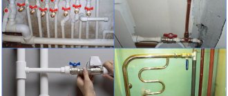
Purpose and areas of application
Bypass valves are installed in liquid and gas pipelines in which pressure may regularly increase for various reasons. The task of this device is to maintain operating pressure in the system. When the pressure increases in the section of the line in front of the installed valve, it releases part of the working medium into the bypass circuit, thereby reducing the pressure in the main system.
These devices are used in systems:
- cold and hot water supply,
- heat supply from any sources,
- cooling,
- conditioning.
A separate area is the automotive industry. They are installed in cooling and fuel supply systems. Bypass valves in turbocharged automobile engines regulate the air supply to the turbocharger.
Automotive engine turbine bypass valve
Bypass valve in a car - where is it located and what is it responsible for?
There are places in cars that even experienced drivers don’t know about; one of these secret components is the bypass valve. How many people have thought about the meaning of the word “car enthusiast”? We are talking about a person who loves cars, is sincerely interested in them, understands the device, and does not rush headlong to a car service when it breaks down. And by revealing the secrets of the car, you and I are gradually becoming professionals.
Bypass for efficient thermoregulation
The video demonstrates a bypass valve from autobot on a Daewoo Nexia
A valve is called a bypass valve if it serves to equalize the pressure of gas, steam or liquid in dissimilar networks, or it plays the role of a fuse, relieving pressure that reaches a certain maximum threshold value. Industrial and domestic heating systems, pumping installations and main pipelines are replete with such devices.
The question arises: where can such a valve be used in a car? Everything is very simple. Its location is the thermostat. Every car enthusiast knows that the main thermostat in a car's cooling system is the thermostat. This small cylinder-shaped element clearly reacts to changes in coolant temperature and redistributes its flow for effective cooling.
The operating principle of the safety valve in the thermostat:
- When a cold engine starts, the coolant begins to circulate in a small circle, that is, bypassing the cooling radiator. This happens until the engine warms up to normal operating temperature.
- The closed main valve located at the top of the thermostat prevents coolant from flowing into the radiator. It is at this moment that the bypass valve is open.
- The valves are located on opposite sides of the thermal expansion element. As soon as the liquid temperature overcomes the 80-degree mark, the main valve begins to open, and the bypass valve gradually closes the end of the lower pipe.
- There is partial circulation of the liquid in a small circle and through the radiator.
- If the temperature exceeds 90 degrees, the bypass closes, and the main valve fully opens the lumen, and the liquid is directed at full speed to the radiator for cooling.
The bypass valve is a simple device
Bypass-type scraper ball valves Strange as it may sound, a bypass valve is a small thin metal round plate with a diameter of no more than 2-3 cm. The plate is pressed against the expansion cup rod by a spring. The valve diameter is selected so that it completely covers the lumen of the lower pipe. Its structure and operating principle are the same for all thermostats, both with a solid and liquid thermal expansion element.
Experts in the design of a factory bypass point to a typical drawback, namely, a rubber diaphragm. Placed on the plate, it begins to collapse and lose its elasticity. This occurs due to the constant impact on the diaphragm of various loads: shock, temperature, boost pressure.
How many bypass valves are there in a car?
Real car experts should know that in some engine models you can find another safety valve. We are talking about cars with turbines that pump air into the combustion chambers of the engine. In this place, the bypass performs a more familiar function, that is, it saves the gas distribution system from excess pressure.
To obtain higher power levels, a turbine is installed on some types of engines, which pumps air. When the engine is running under load and the driver suddenly releases the gas pedal, excess air pressure forms in the system. It is at this moment that the bypass valve is activated and equalizes the air pressure to the required parameters.
Design and principle of operation of any bypass valve
Its body is made of steel or brass. The main element of the internal mechanism is a shutter (flap) that closes the passage opening. The bolt is held closed by a spring. In some models, its role is played by a membrane or diaphragm. The spring force is regulated by an adjustment lever located on the outer surface of the housing.
Valve design diagram
*
The hydraulics of operation are based on the pressure of the working fluid flow in the pipeline on the valve located inside the housing. As long as the force is less than the lever set by adjustments, the drain hole remains closed. As soon as the pressure becomes greater than the setting pressure, the pressure on the spring leads to its compression. As a result, the drain hole becomes slightly open, and part of the flow is bypassed into the bypass circuit, reducing the pressure in the main hydraulic system.
Then the reverse process occurs - a decrease in pressure leads to the spring expanding and the valve closing, and the valve is again ready for the next reset. Pressure equalization occurs constantly, automatically. When the system operates in the “closed water valve” mode, the bypass channel remains constantly open, ensuring constant recirculation of the media flow through the bypass circuit.
Cross-section of the bypass device
Principle of operation
The coolant, water, and gaseous medium, moving through the pipeline, exert pressure on the valve, which is held in place by a spring. As soon as the pressure force reaches a predetermined level, the valve opens and the excess volume of the working medium is discharged through a special branch into another circuit of the system.
After the level drops to normal, the spiral returns the valve to its original position and the contents of the pipeline continue to circulate.
With a membrane mechanism, the passage for the coolant under the influence of pressure is opened by the membrane. When the pressure returns to normal, the membrane returns to its original place.
In a car, the turbine bypass assembly has a damper, the full opening or closing of which depends on the activator lever. The length of its pull can change over time under the influence of various factors. Therefore, this is monitored and the traction is adjusted.
Read also: Which terminal to remove from the battery
Differences from other types of safety valves
Other valves installed for the safe operation of pipelines have a similar device and principle of operation. But they differ in purpose and requirements.
| Valve type | Mechanism of action | Principle of operation |
| Bypass | Installed in a bypass circuit and redirects part of the flow into it | Constantly working as needed |
| Safety | Reduces pressure in the system, throwing part of the media out | In case of emergency pressure increase |
| Reducing | By changing its throughput, it regulates the pressure in the part of the main circuit located after its installation site | Full time job |
The bypass valve reduces the load on the system pumps without changing the amount of media in it.
Causes and Effects
Often, an increase in the pressure level in such systems is associated with the normal functioning of thermal valves that are installed on radiators or a thermal head. When the maximum temperature set in manual mode is reached, the supply of hot coolant to one or another radiator is reduced, which ensures an increase in pressure, and in some cases even the whistle of the radiator shut-off valves.
Of course, this affects, in addition to the level of comfort in the room, also the performance and durability of the heating system and its individual components. To avoid such situations, professionals recommend equipping heating systems with thermostatic valves.
Specifications
*
The main quantities that determine the operation capabilities of bypass devices in the system:
- Passage diameter. Internal cross-section of the carrier passage through the valve. May differ from the diameter of the main circuit of the system.
- Bandwidth. Characterizes the volume of the working medium capable of passing through the valve per unit time at a nominal pressure of 1 atm. Measured in cubic meters/hour.
- Ultimate pressure. The maximum value of excess pressure for which the device is designed to operate. Exceeding this parameter in the system leads to displacement of the valve rod and the beginning of media bypass. Determined at a carrier temperature of 20 °C.
- Setting range. The limits of the possibility of adjusting the excess pressure at which the valve begins to open. The unit of measurement is bar.
Adjustment scale with tuning slider
Types of bypass valves
Although the operating principle and performance characteristics are similar, the devices have additional differences.
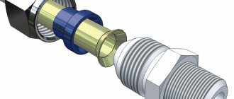
Connection method
On small diameter pipelines (up to 150 mm), the inlet and outlet pipes are usually made with a threaded connection. Options - external or internal thread of the pipe. For large cross-section pipelines, connections are made by welding or using flange connections.
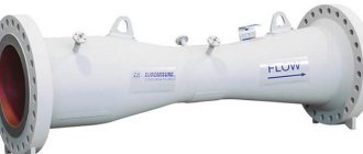
Large Diameter Flanged Valves
Flow direction
*
The valve installed in the main flow usually has an angular shape for connecting the outlet circuit. Valves included in the bypass line can also be direct-flow.
Direct Flow Bypass Valve
Active element
Typically, the outlet is blocked by a shutter or damper. But in some designs, the locking element is a diaphragm connected to a rod. The use of diaphragm options is recommended in pipelines with a working medium containing solid particles in addition to liquid or gas.
Mechanism of action
The difference in the method of influencing the shut-off element led to the emergence of two types of valves.
- Direct action. A simple mechanical device in which the coolant directly acts on the active element of the valve. Inexpensive and relatively easy to maintain.
- With elements of indirect influence. It actually consists of two valves. The small diameter valve works as a pressure sensor and, when activated, controls the main valve rod, which opens the drain into the bypass channel. Characterized by more precise adjustment of the response threshold.
Product functions
The functions of such a device are to promptly discharge excess coolant volumes and thus reduce its pressure level. The general requirements for such nodes are that they must:
- help reduce pressure by promptly discharging excess coolants.
- have precise settings, and for heating systems in residential premises it is desirable that the settings be manual.
- have high strength and reliability.
- ensure the safe operation of heating systems thanks to the reliability of its own design.
Types of bypass valve designs
The bypass valve for heating systems can be of two types, characterized by operating principles. The most common is the spring version, but the lever-load version is mainly used in large highways. The principle of operation of the spring device is that during movement the coolant presses on a special valve, which is restrained by a spring.
When the pressure level is equal to the compression force of the spring, the safety rod opens and excess liquid begins to be discharged using the outlet pipe. After the situation returns to normal, the spring returns the valve to its original position, and the coolant continues to move without restrictions.
Heating system bypass valve
Spring devices are used in systems in which the pipe diameter does not exceed 200 millimeters; in other cases, a lever-load design is used. Its difference from the lever one, first of all, lies in the fact that in the absence of a spring, the rod is fixed using an additional weight, the weight of which can vary. In this case, the critical indicator is adjusted with a certain error, and the adjustment itself is performed by changing the weight of the load.
Device selection criteria
Bypass valves are required in the following types of pipelines:
- Boiler storage systems. The water in them is under pressure, and periodic switching on/off leads to sudden changes in the volume and pressure of the flowing liquid.
- Continuous hot water supply systems equipped with temperature control devices. When the temperature changes, the volume of the medium in the line also changes. Constant adjustment and smoothing of pressure differences is required.
- Multi-circuit heating systems. When any of the circuits is turned off, the pressure in the remaining parts increases. Bypass devices minimize load changes on the system pumps.
- Solid fuel heating devices are not capable of sharply reducing the temperature of the medium after shutdown. Bypassing the flow line, the cooling time can be reduced.
When selecting a suitable bypass type safety device, the following parameters must be taken into account:
- Diameter and connection method allowing it to be included in a regulated line.
- The throughput must correspond to the calculated media outlet in case of maximum load.
- Operating temperature of the device and material of its manufacture.
- The need to adjust the valve actuation point. Its range should be within the planned pressure changes.
Focusing on products from a well-known manufacturer is also important.
Control valve - turbine
| Schematic diagram of turbine regulation.| Changing the location of the statistical characteristics of regulation. |
The piston of the servomotor 8 is then in its middle position, as a result of which the control valve of the turbine 9 occupies a certain position corresponding to the given turbine load. As the generator load increases, the rotor speed begins to slow down. This immediately affects the position of the regulator 1 weights, which move clutch 2 and the associated lever a-c down. Under the pressure of the oil entering through tube K, the servomotor piston begins to rise, and the rod connected to it simultaneously lifts the steam distribution valve 9 and the connecting lever c - a. Lifting the lever c - a moves the servomotor spool rod up, and pistons 5 and b again come to the middle position, as a result of which further rise of the servomotor rod, and consequently valve 9, will stop.
| Schematic diagram of automatic control unit. |
CWD; 7 — low pressure turbine; I am the speed controller; 9 — turbine control valves; 10 — steam inlet valves ChND; p-steam pressure sensor in the control stage chamber; Rpr-steam pressure sensor behind the intermediate superheater; rp z - steam pressure sensor behind the transition zone of the boiler; PK steam pressure sensor behind the primary superheater; DK - visible steam flow sensor from the boiler; GK-feed water flow sensor; Rear sensor of the set load (power) of the unit; RNA - boiler power load regulator; RIT—turbine internal power (load) regulator; RT - fuel regulator; D - differentiator.
The pressure must be regulated either by changing the feedwater pressure or by changing the opening area of the turbine control valve at a constant feedwater flow. Regulating pressure by any of these methods also requires maintaining the steam temperature at the outlet of the boiler at a certain level.
The high-pressure manifold contains drains from four bypass pipes from the stop valve to the four turbine control valves. If the design of the steam inlet part of the turbine allows condensate to accumulate in the steam inlet area (for example, in the side steam supply pipes, as shown in Fig. 9.5), then the resulting condensate is also discharged into the high-pressure drain manifold.
| To explain the possibility of the switch operating during water hammer in the system. |
As a result of the resulting pressure imbalance, the spool moves down all the way, which leads to the closure of the turbine control valves.
In the experimental characteristics there is an additional deviation from the straightened, simplified characteristic due to throttling of steam in the turbine control valves. The degree of throttling (pressure) of steam depends on the degree of opening and the number of control valves. Typically, domestic large condensing turbines have four control valves, so four waves are noticeable in the experimental characteristic. The crest of the wave appears at the moment of the smallest opening of the corresponding control valve - the moment of the greatest pressure loss in this valve at its small opening. Typically, this deviation in steam consumption during throttling does not exceed 2 - 4% of steam consumption and in the conditions of approximate calculations of the characteristics they can be ignored.
| Calculation graphs of block loading at constant initial steam pressure. |
In this case, the maximum final power, slightly less than the rated power, is achieved at the moment the turbine control valves are fully opened.
Fresh steam supplied to the turbine passes through the stop valve, after which it flows through the bypass pipes to the turbine control valves. The stop valve is connected to the turbine control and protection systems.
Fresh steam supplied to the turbine passes through the stop valve, after which it flows through the bypass pipes to the turbine control valves.
DR) - pressure loss on steam pipelines in nominal mode, Pa; DR2 - the same on the turbine control valves, Pa; other designations are given above.
| Functional structure of ECSR-M. |
Installation features
*
The specific installation location of the bypass device depends on the layout and type of pipeline. The valve can be integrated into an additional diverter circuit. For closed-cycle heating systems, excess pressure is released into the return pipeline. It can also be used as a safety valve, adjusted to emergency pressure and with liquid discharge into the sewer system.
In a single-circuit heating main circuit, the bypass valve is installed in the bypass outlet after the injection pump.
Bypass valve for local heating system. Installation diagram.
For greater safety and security of the entire heating circuit, it is advisable to install additional ones in addition to the bypass device:
- check valve to prevent reverse flow direction,
- air vent valve for bleeding air pockets,
- drain valve to completely drain the media from the system,
- for small-diameter cottage-type systems - mesh filters.
In multi-circuit systems, bypass valves are installed in each circuit.
Where to mount and why
The thermostatic valve is mounted by inserting it into the system at a short distance from the liquid supply pump, between the return and supply circuit. The mode for setting the maximum permissible pressure limit of the working medium allows the owner to make the settings manually.
Currently, the range of these products offered by the retail chain is quite large.
But as practice shows, it is better to pay attention to such well-known brands as Mankenberg, Valtec, DANFOSS. They have proven in practice efficiency, reliability and durability in operation.
Purpose
Regulating thermostatic bypass valves are designed to ensure a stable pressure difference between the return and supply pipelines in closed heating systems. When the heat load decreases, the thermostatic radiator valves close. This leads to an increase in the pressure drop between the return and supply pipelines.
Using a bypass valve offers the following advantages:
- reduces the load on the pump;
- protects the boiler from rust;
- prevents the occurrence of noise unnatural for normal operation;
- increases the temperature of the working medium in the return pipeline.
By closing the thermostatic valves on the radiators, we will increase the resistance of our heating system (increase in the pressure difference between the return and supply pipelines). This will increase the load on the pump and lead to noise.
If the pressure reaches the maximum level, which corresponds to the settings of the bypass valve, it opens, forming an adjustable bypass. Also, a bypass valve is installed behind the circulation pump between the return and supply pipelines.
Tips for setup and maintenance
Installing a valve with adjustment of the excess pressure range is worth it to those who already have experience in calculating the required value. The opening of the drain hole begins at the pressure selected by the setting. But it usually opens completely at a pressure exceeding the initial value by 20%. But the calculation cannot be based only on this indicator, because such a decrease in the operating pressure in the system is nonlinear. Relieving part of the carrier already leads to a reduction in the load on the valve shutter. Therefore, to accurately calculate the throughput of devices, they are guided by the diagrams given in the data sheet.
It should be taken into account that the setting error of most regulators is 10%. For initial adjustment and subsequent monitoring, it is recommended to install pressure gauges before and after the bypass point.
The adjustment itself is carried out either by moving the slider along the scale or by rotating the adjusting screw. After setting and checking the required value, the screw is secured with a clamping nut.
Routine maintenance of the bypass valve consists of monthly monitoring of the initial response pressure and its opening speed. You also need to monitor the condition of the filters.
If the valve does not operate correctly, it should be dismantled, disassembled and all parts washed. Perhaps the malfunction is caused by a simple clogging of the mechanism.
Control valve - turbine
The turbine control valves should not open more than the value specified by the manufacturer.
| Elimination of breakdowns of control valves. |
The control valve of the Siemens-Schuckert turbine worked reliably for 12 years.
| Transient process set. |
When the turbine control valves open, steam flow increases, which causes a drop in steam pressure. A drop in pressure leads to the realization of the storage capacity of the boiler. It should be noted that these processes mutually determine each other and occur simultaneously.
Leaving part of the turbine HPC control valves closed when operating at sliding pressure is necessary to ensure rapid load pickup in the event of an emergency decrease in frequency in the power system. For domestic turbines with nozzle steam distribution, this requirement does not conflict with the conditions for ensuring the most economical operating mode of the unit. However, even if this were not the case, as, for example, in turbines with throttling steam distribution, the transition to operation with purely sliding pressure with all valves fully open can only be accepted as an exception, with special permission.
When analyzing the model of a turbine control valve, the assumption is made that the value of the valve flow area is determined by the critical throttling of steam.
When the turbine control valves open ahead of time, the value of complex B will be positive, and, consequently, the steam flow to the turbine increases both due to the increase in heat release in the furnace and due to the storage capacity of the boiler.
An impulse from the servomotor of the turbine control valves is supplied when the valves are completely closed. When the BROU is turned on from this impulse, the idle speed of the turbine can be maintained. However, the effect of this impulse manifests itself with a large delay. Since during operation of a turbine with a sharply variable load, at some moments the control valves can reach the completely closed position, the impulse to turn on the BROU based on the position of the turbine servomotor can only be given with a time delay, for which a special time relay PB is provided. This further increases the delay in issuing the command to turn on the BROU.
The impulse to change the position of the turbine control valves was rejected by the turbine plant due to its insufficient accuracy.
Underpower occurs when the turbine control valves are fully open and when they cannot be opened beyond a certain amount. In any of these cases, an increase in steam production at the boiler leads to an increase in pressure in front of the turbine.
Thanks to the opened drain from this pipe, the turbine control valves close.
| Minimum block loads. |
When operating at a sliding initial pressure, all turbine control valves are open, and the steam flow is determined by adjusting the combustion mode.
| Control diagram of a block power plant. |