09/05/2019 Author: VT-METALL
Issues discussed in the material:
- Where are pipeline supports used?
- What types of supports for pipelines are there?
- What is the difference between fixed and sliding supports for pipelines?
- What standards and regulations are used in the manufacture of pipeline supports?
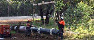
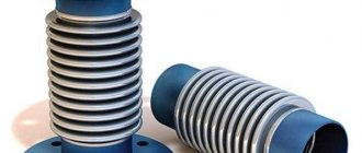
Pipeline supports are significant elements of the entire communications system. They take on the weight of the pipes, and then the entire load is distributed over the supporting structures or transferred directly to the soil. Thanks to the supports, it is possible to move the pipes in the longitudinal direction, fix them and protect them from premature abrasion. Today, manufacturers offer a wide selection of communications and corresponding supporting elements from various materials, all of them have their own technical characteristics - we’ll talk about this further.
Pipe supports: use cases
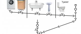
The main function of pipeline supports is to secure the communication in a certain position. They also prevent pipes from deforming under the influence of temperatures and vibrations. The fact is that vibrations often occur when transporting the working medium through the system.
It is extremely important to pay utmost attention to the installation process, since the reliability of communications depends on the supporting elements. If mistakes are made, they simply will not cope with the tasks assigned to them.
Let’s say right away that these products are used in a variety of fields and differ in type and purpose. So, installation of communications cannot be done without them:
- at enterprises;
- in housing and communal services;
- at nuclear power plants;
- at thermal power plants;
- in the gas and oil sectors.
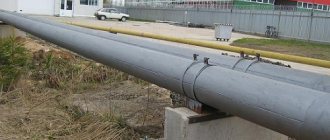
If we are talking about a gas pipeline, then especially serious requirements are placed on the supports, including when the pipeline runs through regions that are unfavorable from a climatic point of view. It is equally important that the supporting structure protects the pipes from damage in the most vulnerable places, that is, at the fastening points.
The terminology of GOST 22130 defines supports as a structural element of the pipeline, that is, they cannot be called a transitional structure between pipes and foundations.
As we have already said, supporting elements are used when laying communications in a wide variety of industries. The necessary products are selected depending on their purpose in such a way that they allow the transmission of axial, transverse, vertical loads, torques to the soil or load-bearing structures.
Suspended pipeline supports
Suspended pipeline supports can be spring or rigid. Supports with a spring structure are designed for pipeline systems with pipe diameters from 150 to 1400 mm. These products are used for both vertical and horizontal pipelines.
The number of spring blocks used is calculated based on the possible loads on the pipeline elements and its initial characteristics. The spring supports are secured using clamps, support beams, traverses or welded feet.
Rigid suspension supports are used for pipeline systems whose diameter varies from 25 to 600 mm. Such supporting metal structures can have one or two rods; they are secured using clamps, support beams or welded joints.
Purpose of pipeline supports
It is possible to achieve tightness and operational safety of the system only if two parameters are observed at once: the selection of high-quality pipes and the use of additional equipment, that is, supports for process pipelines.
According to the documentation, we are not talking about a separate construction part, but about a structural element of communication.
Let’s immediately name the useful functions of this component of the pipeline:
- Protection of the pipe from damage at the point of contact with the structure.
- Ensuring the pipes are positioned correctly.
- Load distribution along the entire length of the structure and its transfer to the ground.
- Elimination of vibrations, reduction of voltage in the system.
We recommend articles on metalworking
- Steel grades: classification and interpretation
- Aluminum grades and areas of their application
- Defects in metal products: causes and search methods
The popular name “suspensions” has been assigned to supports for fixing pipes, but this term is not suitable for every type of fastening.
The fact is that all supporting structures existing today are divided into types based on:
- immobility/mobility;
- installation method.
If we talk about the installation method, then similar products can be:
- hanging;
- ordinary.
Suspended models are attached to ceilings, slabs and other means. They are considered movable supports for the pipeline, that is, they can move in two directions: across or along the axis of the structure. Whereas the stationary ones have a different task - they rigidly secure the pipe in a certain position.
Why are movable models needed?
- They reduce the stress coefficient in the system walls.
- The support reaction force of the pipeline is transmitted to the supporting structure, without changing the position of the point at which the transmission occurs.
Types of pipeline supports
1. Hull supports.
To connect structural elements in space, a box-shaped housing is often used. It is made of sheet steel or welded from individual elements. Body supports are mounted on a beam, have stiffening ribs, and are supplemented with cushions, clamps and yokes.
When using the housing, the pipe rises by 100–200 mm, making it convenient to fasten and maintain during operation. If we compare the cost of a bent angle and a range of rolled metal products, then purchasing the former turns out to be more profitable and reduces the cost of the entire structure.
2. Frameless supports.
This is a traditional model, which is a sheet steel cradle bent in accordance with the outer shape and diameter of the pipeline. Most often this element is called a “pillow”. It can also be equipped with a round, strip or tape clamp and a support plate, which has holes for fixing.
The design is simple, its production requires a minimum amount of materials, and it itself consists of a very small number of parts. For this reason, the open-frame model is called the most affordable one used in pipeline construction. For such support elements there are markings T11, HB, OPB.
3. Tubular supports.
If we talk about the design of this element, then we have a vertically located pipe, welded to a plate with holes for installation. To increase the contact area of the support pipe with the pipeline, a saddle-shaped cut is made at its upper end with a laser or cutter, which corresponds in shape to the main pipe.
When releasing such models, they are based on the OST 36-146-88 standard. This type is suitable for pipelines with a diameter in the range of 57–630 mm and medium temperatures up to +450 °C. There are currently four versions in total: A1, B1, A2, B2. Such products are marked TR; stainless steel, structural and carbon steel are used in their production.
4. T-bar supports.
T-bar elements can have different designs and are made of two types:
- Welded. In this case, a piece of the brand is installed on a single shelf, plates are welded at the ends, and a radius cut is made in their upper part in accordance with the diameter of the pipe for better fixation of the pipeline.
- Clamps. We are talking about strip or tape clamps that are welded on top of a piece of rolled metal, and holes for fastenings must be provided in its shelf.
These types of T-bar support structures are labeled as TP and TX. Various methods of connecting pipeline elements can be selected, thus achieving complete immobility of the unit or several degrees of freedom of the connection.
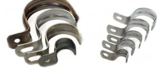
5. Clamp supports.
They occur when using both movable and fixed connection methods. Then the following types of fastening can be used:
- bar clamp;
- strip clamp;
- band clamp;
- flat clamp;
- rope clamp;
- mounting on the body;
- with frameless supporting structures;
- for welded and sliding supports for pipelines;
- the clamp is used as a guiding element.
The clamp tightly grips the pipe on all sides; gaskets made of dielectric and antifriction materials can be used with it. Also, with this fastening method, one degree of mobility of the pipeline along its axis can be achieved.
The classic model is an inverted U-shaped structure with or without stiffeners.
Clamp elements are used for pipelines with a diameter of 57–377 mm, while the yoke type is suitable for sizes 377–1420 mm. It is worth noting that assembly units can be marked differently, this is due to the fact that several standards are used in their production.
6. Welded supports.
Sliding and movable support structures are rigidly attached only to the base/stands or directly to the base and pipe. Welded support structures come in the following modifications:
- sliding guide;
- sliding motionless;
- steel;
- motionless;
- sliding;
- corner;
- on a beam with eyes.
For their production, they take rolled and bent angles, T-bars, channels, pipes or curved, welded bodies.
7. Supports for vertical pipelines.
According to OST 36-17-85, supports for technological vertical pipelines and piping of technological lines are manufactured. Most often we are talking about a strip, rod or yoke clamp, which is attached to a corner or in a bent body.
In the documentation, such structures are usually referred to as VP; usually these are fixed models. In this case, the main characteristics are considered to be material, diameter, face-to-face length, temperature and pressure of the working medium.
8. Rope supports.
A yoke is nothing more than a type of clamp, supplemented with special fasteners or studs. Yoke models are divided into types according to the design of the assembly unit and are:
- tubular;
- strip;
- case;
- stamped;
- stamped and welded.
This element is installed in this way: the pipe is laid on a cushion or cradle with holes for the studs, after which the yoke is pulled on top of the threaded connections. To make it easier to clamp the pipe, special mechanisms, claws, traverses, clamps or beams can be used.
9. Roller supports.
The design of this model stands out from the general background due to the following characteristics:
- two or more support platforms are provided;
- installation is carried out between the bearing supports;
- axial displacement of the pipeline by a specified amount is allowed;
- It is allowed to move the pipes sideways by 50 mm.
It is possible to produce one- and two-level elements, with one roller and several blocks, and the enterprises also produce clips for pipelines of energy facilities, steel and spring models. Rolling elements can significantly reduce the level of friction, and hence the wear rate of the elements of the entire structure. As a result, the service life increases, and assembly units are easier to repair.
10. Side supports.
The design of this element includes a plate and a support, which is necessarily equipped with several stiffening ribs for reinforcement. This model differs from the welded one only in its location in space, because it is mounted on a vertical surface, due to which it compensates for lateral loads, but does not perceive vertical forces.
Such elements are marked as T10 and are suitable for pipes with a diameter of 194–1,420 mm.
11. Frontal supports.
If we consider the location of the frontal models relative to the flow of the working medium and the body of the pipes, then they are installed in a transverse projection. These products are usually divided into types based on the material of manufacture and design:
- panel panels are made of reinforced concrete, often having several stiffening ribs;
- thrust ones are a pair of stops in a vertical or horizontal plane on both sides of the pipeline; they can also be four stops on all sides.
Double-supported frontal elements are installed when it comes to small axial loads, while four-supported ones are necessary for serious loads. If necessary, the entire structure can be reinforced with half rings and stiffeners.
12. Fixed supports.
This type of structure is necessary if it is necessary to exclude any mobility of communications relative to supports and foundations. Manufacturers offer the following design options designed for different operating conditions:
- "dead";
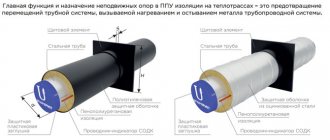
- for pipes in thermal insulation PPU;
- frontal and side thrust;
- yokes and clamps;
- hulled and unhulled;
- for vertical boxes;
- persistent reinforced;
- panel reinforced concrete;
- welded and steel.
To designate these pipeline elements, the abbreviation NOP is used. This type is suitable for installation with pipes with a diameter of 32–1,420 mm and is intended for conditions with increased operating loads.
13. Movable supports.
If it is necessary to achieve one or more degrees of mobility of the pipeline relative to the foundation or supporting structure, various movable models are used:
- clamp OPC;
- welded OPP;
- unframed OPB.
The rules for the manufacture of such supports for pipelines are established by GOST 14911-82, OST 36-94-83 and 36-146-88, in addition, the specifications of individual enterprises, drawing albums T-MM-26-05, and other documentation are taken into account.
14. Sliding supports.
This type of moving elements provides one degree of freedom in the axial direction. In this case, the following execution options exist:
- steel and welded;
- underlay and in a case for pipes in PPU thermal insulation;
- for pipelines of thermal and nuclear power plants;
- with flat clamp and bracket;
- sliding fixed and guides of several types;
- dielectric and yoke;
- clamp and frameless.
To resist rapid wear of pipes and system elements, anti-friction gaskets, rollers and blocks are used.
15. Adjustable feet.
They are chosen if precise vertical positioning of individual sections of the pipeline is necessary. Let us say right away that such structural elements necessarily have movable wedge stops. Assembly units are marked OR, and in their manufacture the standard TU 5263-003-93646692 is used. Another important element of such a supporting structure is the support. It is raised and lowered by moving the wedge stops, which are attached to the plate by bolted connections.
16. Dielectric supports.
Such elements are necessary to protect the pipeline from stray and induced currents. To do this, use a gasket made of any dielectric material, for example, paronite, which has anti-friction properties.
17. Supports for reinforcement.
OST 36-17-85 establishes standards for the production of structures for the installation of OKA pipeline fittings. From a technical point of view, these are four stiffeners that are cross-welded together and mounted on a support plate. In their upper part, the stiffeners follow the outer contour of the installed pipeline fittings.
18. Unloading supports.
This design is necessary to compensate for water hammer, vibration and mechanical loads that cannot be avoided during the operation of pumping and compressor equipment. Such an element consists of a pipe and has several degrees of freedom relative to the foundation. In its production, they rely on SNiP 3.05.05-84, and GPA markings are used.
Types of supports
Pipeline supports can have different designs, depending on the principle of operation. First of all, a distinction is made between fixed and movable supports.
. The former provide rigid fixation of the pipe (the supports themselves may move in this case), the latter allow for the possibility of axial or lateral displacement.
Movable supports are divided into the following types:
- sliding supports (designed to absorb loads caused by temperature changes, level out pipeline deformations, and do not interfere with the movement of pipes). Sliding supports are attached using rollers, clamps, welded joints, hangers, and pins; used for above-ground installation of pipeline systems;
- roller supports (the combination of a roller block and a sliding support provide a fairly high degree of mobility, allowing the pipeline to move along the axis without interfering with lateral deviations);
- suspended pipeline supports are spring-loaded and rigid.
How does a fixed support for pipelines work?
Fixed structures are necessary in cases where rigid fastening of the system is required. In this way, it is possible to prevent its shifts in any of the possible directions.
Fixed elements are used in the installation of pipelines, which are installed in the following ways:
- external;
- internal (underground).
During the installation of sections of the system, the supporting structures are fixed using reinforced concrete frames. You need to understand that the latter are located at different distances from each other, dividing communications into segments. The length of the segment is related to the characteristics of the special compensators installed on it.
During both external and underground installation of communications, fixed elements are actively used. If a channelless method is used for laying underground, choose supports with high-quality waterproofing. Usually the role of the latter is played by a polyethylene shell. When it comes to external installation, galvanized waterproofing is preferred.
For a fixed installation method, the following elements are used:
- steel pipe;
- steel sheet obtained by hot rolling;
- polyurethane foam (PPU);
- heat-resistant tape;
- galvanized shell;
- centralizer;
- polyethylene shell.
For the manufacture of fixed steel supports for pipelines, the most durable and reliable grades of this metal are used.
The steel sheets used in this case can be of three types - it all depends on the quality:
- ordinary;
- low alloy;
- structural (considered the highest quality).
A centralizer is an element that simplifies the alignment of pipe ends before connecting pipeline elements. Today there are two types of centralizers:
- external;
- internal.
In accordance with the name, external ones perform alignment from the outside of the pipe and can be:
- link;
- eccentric;
- hydraulic jacks.
The first ones are necessary for centering pipes with a cross-section in the range of 57–2,224 mm. Unlike other models, they have increased resistance to low temperatures, since they are made from frost-resistant steel. Eccentric centralizers can be used when working with pipes of any cross-section. The latter type is used exclusively when aligning pipes with very large weights or when there are deformations on them. Such devices provide a force of 12 tons.
If we talk about internal centralizers, they are distinguished by one important feature: they allow long-term welding of pipes from the inside. As a result, the quality of seams is significantly improved. However, these products also have disadvantages, the main one of which is their heavy weight, that is, their transportation is impossible without special equipment.
Fixed support structures for pipelines are used in construction:
- main gas or oil pipelines;
- various types of communications at enterprises;
- pipelines to nuclear power plants and thermal power plants.
In addition, it is the fixed elements that are used in the construction of communications in regions with low temperatures, thus increasing the service life of the entire structure.
These elements are installed in systems used in completely different areas. They divide the entire system into separate segments in which bellows-type compensators are installed. The latter are designed to protect the pipeline from deformation that is possible when the ambient temperature drops.
Fixed supports of steel process pipelines are welded to platforms and mounted to the pipe using fasteners. To achieve the greatest reliability, metal plates are also welded close to the ends of the clamp.
Documentation
Chapter 11. PIPELINE INSTALLATION TECHNOLOGY
Installation of pipelines should be carried out in accordance with the project, detail drawings (CDD), work execution plan (WPR) and safety regulations. Pipeline installation is carried out mainly with ready-made units manufactured in pipe procurement shops complete with fittings, as well as pipeline blocks assembled on site, with maximum mechanization of installation work. Installation of pipelines “in situ” from individual pipes and parts is allowed only in exceptional cases.
§ 1. PREPARATORY WORK
Before starting work on pipeline installation, the foreman of fitters studies working drawings, specifications, PPR and other technical documentation for the facility being prepared for installation. Having received an installation task, workers must familiarize themselves in detail with the technical documentation and safety regulations. At the same time, they study the pipeline laying diagram, plans and dimensions of the building, drawings of piping of apparatus and equipment, fastening of pipelines and supporting structures, specifications for products and fittings.
Before installation of pipelines begins, the following preparatory work must be completed:
Compliance with the design for the installation of support structures for pipelines, installation of embedded parts for fastening pipelines, the presence of holes for pipelines in building structures, fastening of fixed supports of free-standing support structures and overpasses were checked. Installation and sealing of embedded structures and holes for pipelines are provided for in the construction part of the project and must be carried out by the construction organization.
buildings, building structures, overpasses, trays, trenches are accepted according to an act from construction organizations with verification of their construction readiness for the installation of pipelines and compliance with the design marks to which the pipelines are attached in the installation drawings. When accepting trenches, the compliance of their dimensions and elevations with the design ones, the correctness of the slopes, compliance with the slopes, the quality of the bed and the condition of the fastenings must be checked. The bases of trenches in rocky soils must be leveled with a layer of sand or gravel at least 20 cm thick;
Compliance with the drawings of the types, sizes and locations of fittings of the equipment to which the pipelines are connected, and the accuracy of its installation in the axes and marks were checked. All deviations from the project must be recorded in the work log;
Sites for intermediate storage and consolidation of pipeline units have been organized. Intermediate storage of pipes, parts and assemblies is carried out in open areas along each line separately and they are located so that free passage and access to them is ensured for inspection, checking markings and performing loading and unloading operations. When stored in an open area or in rooms without a wooden floor, all assembly blanks, regardless of the nature of their installation, are laid on wooden pads with a height of at least 200 mm so that it is possible to strap them when submitting for installation. It is recommended to deliver finished pipeline assemblies to sites in containers, which creates convenience during storage, on-site movement and loading and unloading operations. It is recommended to place signs near the storage areas of workpieces indicating the unit number and line number for the project;
prepared workplaces, tools, installation devices; equipment for welding stations; the necessary scaffolding recommended by the PPR has been installed;
units, sections, pipes, fittings, compensators, stops, hangers and other products are accepted for installation; their completeness, compliance with the project requirements and delivery conditions were checked. Industrial installation methods predetermine that components, supporting structures, supports and hangers are delivered to the installation site from pipe procurement shops with the maximum degree of factory readiness and completeness. The completeness of the delivery is checked according to specifications, packing lists and other shipping documents, and the condition is checked by external inspection. When loading, it is not allowed to dump pipe blanks and store them in bulk.
Before the installation of pipelines for sanitary systems begins, it is necessary to check the completion of general construction work in buildings and structures, including accepting holes and grooves for installation for laying pipelines in compliance with the dimensions given in the table. 61.
When constructing external water supply, sewerage, gas pipelines and others, before digging trenches and pits, all underground communications must be opened. Communications are opened using shovels, without the use of percussion tools. The autopsy areas are fenced off and these areas are illuminated at night. Existing communications that cross the pipeline being laid or are located parallel to it at a distance that is unacceptable according to the standards are shifted in accordance with the project. Before proceeding with the installation of external pipelines, the route passing
Table 61. Dimensions of holes and grooves for laying pipelines of sanitary-technical systems, mm
| Type of gasket | |||
| Pipe systems | open | hidden | |
| ahb | V | G | |
Heating
| Riser | yuohyuo | 130 | 130 |
| Two risers | 150ХУ0 | 200 | 130 |
| Connections to devices | yuohyuo | 60 | 60 |
| Main riser | 200ХУ0 | 200 | 200 |
| Highways | 250X300 | — | — |
| Plumbing and | sewerage | ||
| One water riser | yuohyuo | 130X100 | 130 |
| Two water risers | 150X100 | 200 | 130 |
| One sewer riser | |||
| DH 57 mm | 150ХУ0 | 200 | 130 |
| The same, ?>„ 108 mm | 200X200 | 250 | 200 |
| Two water risers and | |||
| one sewer riser | |||
| DK 57 mm | 200X150 | 250 | 130 |
| Same, 108 mm | 350X200 | 280 | 200 |
through a populated area, along its entire length should be fenced on both sides with inventory boards with the installation of warning signs. In areas of heavy traffic and pedestrian traffic, red flags should be installed on the fence.
The laying of pipelines must be preceded by a breakdown of their routes, which is carried out in accordance with the project, where the connections of the pipeline axes to the floors, walls and columns must be indicated. The axes and marks of the pipelines are transferred to the installation site and the installation locations of supports, fasteners, compensators and fittings are marked.
When laying out the route of intra-shop pipelines, the axes and marks are fixed with the help of signs applied directly to the walls of the building, metal and reinforced concrete structures with a scriber or oil paint. The breakdown of straight horizontal axes is carried out first of all; this is done using a steel string with a thickness of 0.2-0.5 mm or a nylon thread, along which the axes of the pipelines are marked on the structures, indicating vertical marks (taking into account the required slope of the pipeline). The heights of the horizontal axes of pipelines are found by measuring from the level of the finished floor with a plumb line and a steel tape measure. If it is impossible to measure from the floor or ceiling, marks from existing benchmarks (elevation marks established by construction organizations) are transferred to the pillars and columns of buildings along the route of the future pipeline every 10 m using a level. From the transferred mark, measure the distance to the pipeline axis, which is determined by subtracting the benchmark mark from the design distance to the pipe axis. A square is applied to the pipeline axis mark transferred on the column and a horizontal line is drawn with bright paint. The resulting mark is transferred to the next column. If the pipeline will be laid with a slope, then the mark is transferred to the next column, taking into account the direction and slope indicated in the project. Typically, all process pipelines are laid with a slope towards their possible complete emptying of residual liquid by gravity.
The minimum slope values for process pipelines for various purposes, m, per 1 m length are as follows:
Gas pipelines and pipelines (in the direction
First, the route of the main line is broken down, and then the axes of the branches to devices, machines, fittings or to other lines. Along these axes, the installation locations of compensators, fittings, movable and fixed supports, pendants, and brackets are marked.
When laying non-insulated pipelines in channels, on high and low supports and overpasses, the distance between the walls of the pipes in the clear is taken taking into account the location of the flanges staggered, mm not less: for pipes with ?>„, respectively 57...108-80; 108…377—100; more than 377-150.
The laying of pipelines inside buildings and installations is carried out on supports along walls and columns, on suspensions to floor beams and ceilings, taking into account the free movement of lifting and transport equipment. The distance from the floor to the bottom of the pipes or the surface of their thermal insulation must be at least 2.2 m.
The distance between the outermost pipeline or the surface of its thermal insulation and the wall must provide the possibility of free thermal expansion, inspection and repair of the pipeline and fittings and is taken in the light to be at least 100 mm. Pipelines laid along the walls of buildings should not cross window and door openings. When laid along the external walls of buildings, pipelines are located at least 0.5 m above or below window openings.
Upon completion of work on laying out the pipeline route, a report is drawn up, to which a list of axes and turns is attached.
§ 3. INSTALLATION OF SUPPORTS AND SUSPENSIONS
Supports and hangers are used to fasten horizontal and vertical pipeline lines to buildings, structures and technological equipment. Based on their purpose and design, supports are divided into fixed and movable.
Fixed supports rigidly hold the pipe and prevent it from moving relative to the supports and supporting structures. Such supports absorb vertical loads from the mass of pipelines with the product and horizontal loads from temperature deformation of pipelines, water hammer, vibration, etc. Depending on the method of attachment to the pipe, fixed supports are welded and clamped. In clamp supports, special stops are welded to the pipe to prevent the pipe from slipping in the support. Fixed supports are manufactured according to the standards of design organizations and manufacturing plants.
Movable supports support the pipeline, but do not prevent it from moving due to temperature deformations. They only support vertical loads from the mass of the pipeline with the product. They are divided into sliding, roller, frameless and others. Movable supports are manufactured in accordance with GOST 14911-82* and GOST 14097-77, OST 36-11-75, as well as according to the standards of design organizations and manufacturing plants.
Suspensions are attached to supporting structures and building floors using rods with bolts or welded eyes. The length of the rods is set by design and adjusted with nuts or couplings. Pendants are manufactured in accordance with GOST 16127-78, OST 36-12-75.
Installation of supporting structures, supports and hangers is carried out after the pipeline route has been laid out, when the axes have been marked and the mounting locations for fittings and compensators have been determined. Supporting structures are most often attached to reinforced concrete elements of buildings - columns, crossbars, panels, welding them to embedded parts.
After the supporting structures are secured, supports and hangers are usually installed in the design position along with the pipeline assemblies and blocks. If it is necessary to pre-fix the installed pipelines on temporary supports and hangers (in the case of installation of pipelines of a complex configuration in cramped conditions, etc.), the latter must correspond in strength to the weight of the pipeline fixed to them and be installed on durable structures. After installation of all pipeline components and welding of installation joints, permanent supports and hangers must be placed, and temporary ones must be removed.
When installing supports and support structures under pipelines in accordance with SNiP 3.05.05-84, the deviation of their position from the design plan should not exceed ±5 mm for pipelines laid indoors and ±10 mm for external pipelines, and the slope should not exceed +0.001 , unless other tolerances are specifically provided for by the project. To level the elevations and ensure the design slope of the pipelines, it is allowed to install steel spacers under the soles of the supports and weld them to the embedded parts or supporting structures.
The length of the suspension rods is changed due to the threads on them.
Welded joints of pipelines must be at a distance of no less than 50 mm from the supports, and in steam and hot water pipelines controlled by the USSR State Technical Supervision Authority - no less than 200 mm. It is recommended that flange connections of pipelines be located, whenever possible, directly at the supports.
Fixed supports are welded to the supporting structures and securely fixed to the pipe using clamps with locknuts installed on the bolts. The support pad and clamp are pressed tightly against the pipe. To prevent the pipe from moving in a fixed support, thrust plates are welded to the pipe, which should rest against the ends of the clamps. The stops are installed so that the gap between the clamp is no more than 1.5 mm. The surface of the stops and the surface of the pipe at the installation sites must be cleaned with a hand grinder before welding. Thin aluminum spacers are installed between the alloy steel pipe and the carbon steel support or clamp to protect the contact points from electrochemical corrosion.
Movable supports and their parts should be installed taking into account the thermal change in the length of each section of the pipeline, for which purpose the supports and their parts must be shifted from the axis of the supporting surface in the direction opposite to the pipeline extension. The displacement value is usually taken according to the design to be equal from the base to the full thermal elongation of a given section of the pipeline. The suspension rods of pipelines with thermal elongation must be installed with an inclination to the side. The amount of displacement and the direction of preliminary tilt of the rods are indicated in the project.
§ 4. INSTALLATION OF PIPELINES
With industrial methods of work, installation of tr^. pipelines are carried out in units, sections and blocks. Nowadays, installation by aggregated blocks has become widespread, i.e., pipeline blocks are assembled together with technological equipment and installed on a common frame.
The enlarged assembly of the blocks is carried out on stands and racks located in the operating area of the assembly cranes. Here it is advisable to use stands 21338 (see Fig. 10) and centralizers (Fig. 46). Before assembling the blocks, temporary plugs are removed from the fittings and assemblies and the flanges and pipe ends are unpreserved. After control measurements of finished units and checking the location of fittings on the equipment, the assembly of blocks begins. The dimensions and weight of the blocks should ensure ease of transportation to the installation site and installation in the design position. Knots and blocks must remain strong when lifted, otherwise they may become deformed. If necessary, temporary structures must be installed to provide the required rigidity.
Rice. 46. Pipe welding centralizer TsT-426:
1
- screw; 2 - nut; 3 — cheek; 4 - link; 5 - roller; 6 — straightening
points
It is recommended to begin installation of pipelines with equipment piping, i.e., first of all, install units and blocks that include fittings, as well as basic units with fittings for the main main sections of pipelines.
Straight sections are laid after installation and fastening of adjacent units and blocks. It is advisable to attach supports and hangers to the units and blocks being lifted; this facilitates subsequent alignment. When installed in the design position, units and blocks, as well as sections and individual pipes must be laid on at least two supports and securely fastened. Temporary fastening of pipelines during the installation period is permitted in exceptional cases. Pipelines laid through walls, ceilings or other elements of buildings must be enclosed in sleeves in accordance with the design instructions. In the absence of instructions, it is recommended to use pipe sections with an internal diameter 10-20 mm larger than the outer diameter of the pipeline section enclosed as sleeves. The ducts should protrude 50-100 mm on both sides of the building element crossed by the pipeline. Sections of pipelines in sleeves should not have joints. The gap between the pipeline and the sleeve is filled on both sides with asbestos or other non-combustible materials that allow the pipeline to move in the sleeve.
Lifting and installation of units and blocks into the design position is carried out using cranes, rigging equipment and devices provided for by the PPR. Hoists, blocks and other rigging equipment used in the installation of pipelines are allowed to be attached to components of building structures that have the necessary safety margin. If there are no relevant instructions in the PPR, the possibility of fastening to building structures must be agreed upon with the design organization.
Pipeline fittings are usually installed complete with units or blocks. When installing fittings that are not included in units or blocks, it is first secured to supports, after which a pipeline is connected to it.
It is advisable to install external above-ground pipelines in enlarged blocks and sections. The dimensions and designs of blocks or sections are determined in the PPR and depend on the designs of overpasses, the number and location of pipelines on overpasses, their diameters, the availability of lifting mechanisms at the installation organization, as well as installation conditions. The enlarged assembly of blocks and sections is carried out on stationary or mobile lines. Sections are lifted onto supports or trestles usually using two cranes, the types of which must be specified in the PPR.
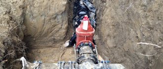
Installation of underground pipelines is carried out in the following sequence: trenches are developed; clean the bottom and walls of the trenches; dig pits in places of welding and insulation of joints; arrange the foundation for the pipeline; make the bottoms of wells and chambers; lower the pipes into the trenches, laying them on the base; closing joints are assembled and welded; install connecting parts and fittings, tamp and sprinkle the pipeline with soil (except for joints); blow the pipeline with air; preliminary test the pipeline for strength; isolate joints; filling up the pipeline. The final testing of the pipeline is carried out after completion of construction and installation work.
To center the ends of pipes assembled for welding and eliminate discrepancies between the edges along the perimeter of the pipes, centralizers are used. The pipe welding centralizer TsT-426 is a ball-and-link plate chain assembled from links mounted on freely rotating rollers with threaded holes into which retaining screws are screwed. The right extreme link is made in the form of two plate hooks that close the centralizer on the axles of a nut having a right-hand thread. To tighten the centralizer in joined pipes, use a screw located parallel to the tangent to the circumference of the pipe. The screw has right and left thrust threads. It is recommended to rotate the screw using a ratchet wrench with adjustable torque with a replaceable head with a 14 mm opening.
To center the pipes during their assembly, it is necessary to lay the centralizer so that both rows of plates are located symmetrically to the joint of the pipes, then the hooks are put on the trunnions of the right nut and by rotating the screw, the centralizer is pulled until the axes of the pipes being joined are aligned. Where it is necessary to eliminate the displacement of the edges, the retainer screws are screwed into the threaded holes of the rollers. In this case, the torque should not exceed 30 Nm.
When changing the diameter of the assembled pipes, the number of centralizer links is changed.
Technical characteristics of centralizer TsT-426
Outer diameter of joined pipes,
mm……….219—426
Maximum tightening torque, Nm:
Manufacturer…….Poltava experienced
foundry-mechanical plant Minmontazh-
special construction of the Ukrainian SSR
It is recommended to install pipelines laid in trenches in sections and strands up to 1000 m long. In this case, ready-made coded pipes or sections 24-36 mm long are laid out at the edge of the trench and assembled
and
weld their joints in a fixed position. The lashes are assembled on plank beams or on excavated soil for the convenience of their subsequent slinging when laying in a trench. A distance of up to 35 m should be provided between the sunbeds, and the bottom of the trench should be planned taking into account the design slope. In order not to damage the insulation, the pipeline is lifted using special slinging devices - towels consisting of a steel rope and an internal protective sheath made of rubberized fabric. It is recommended to lay the string in a trench using three cranes located along the string at a distance of 15-40 m from each other, depending on the diameter of the pipelines.
Chapter 12. testing and commissioning of pipelines »
Library "
What are the benefits of sliding supports for pipelines?
Sliding models are necessary if communications pass along the surface of the earth. This ensures free movement of the pipeline in horizontal and vertical planes. Also, such devices protect the entire structure from premature abrasion.
It is impossible to do without sliding elements when installing systems that experience loads during seasonal temperature changes, because at this time the pipes expand and contract in two planes at once.
Thanks to sliding models, it is possible to achieve stability of communications and balance their movement in space that occurs when temperatures change.
The sliding model includes the following components:
- the base, the role of which is often played by a corner;
- semicircular metal pipe holder;
- pad;
- fasteners, that is, nuts and bolts.
Movable models are available in three types:
- hard;
- elastic;
- constant force designs.
Rigid models, in turn, are:
- guides;
- rigid suspensions;
- sliding supports.
The former do not allow communication to move downwards and horizontally. Suspensions of the second type allow you to achieve the greatest mobility of the entire structure. While the latter type eliminates the pipe moving down in the vertical direction. Elastic supports can boast such rigidity only if the pipe moves vertically. Then the following pattern works: the higher the load on the supporting element, the further the pipe moves. Note that the constant force support copes with any load, regardless of the displacement of the communication.
To protect this element of the system from rust, it is primed in several layers. Or it can be coated with primer enamel. But the highest degree of corrosion protection is provided by powder coating or galvanizing.
Typically, durable carbon steel is chosen as the material for the manufacture of such products. But it has to be replaced with low-alloy grades when it becomes known that the pipeline will be operated under conditions of large temperature fluctuations.
When classifying sliding supports for pipelines, it is not the price that is taken into account, but their design, therefore the following types are distinguished:
- on brackets (fastening elements);
- clamp;
- ball;
- dielectric;
- roller (roller).
Due to the rollers used in it, the roller design reduces the friction force between its base and the upper part. Note that friction is generated when the pipeline moves.
Dielectric sliding elements are chosen for pipes in the manufacture of which the following are used:
- carbon steel;
- low carbon steel.
Such structures require insulation from a special material - sheet paronite, which includes:
- rubber;
- asbestos;
- additional powder additives.
For the manufacture of ball sliding elements, steel is used, and they are considered a specific fastener. The fact is that with their help the pipe can move in two directions at once: longitudinal and transverse. Therefore, such models are most often installed at power plants and heating mains.
Typically, sliding type devices are isolated from metal casings using waterproofing. And the inner surface of the pipe and the waterproofing material are lubricated with a special graphite lubricant, which prevents friction. Next, weld the clamps and tighten them securely. It is important that when installing such structures you can do without special equipment, due to which the whole work takes much less time.
Distance between pipeline supports
However, it is not enough to know the types of supports for pipelines and buy all the necessary elements. For competent construction, you need to clearly understand the distance between these structures, because only in this case the system will work properly. The distance is set in accordance with the requirements specified in the relevant documentation, as well as on the basis of information about the scope of operation of the pipeline, its weight, and possible deflection during service.
The values are calculated based on data from the table “Design of Heat Networks” by A. A. Nikolaev. So, for horizontal placement, the table suggests the following calculation: with a minimum pipe diameter of 20 mm and a maximum working environment temperature of +60 ˚C, the supports should be 60 cm apart from each other. The rule works here: the larger the pipe diameter, the larger the pitch used.
The same calculation principle is used if vertical placement is planned. Let’s say the main line has a diameter of 40 mm and a temperature of +20 ˚С, then the length of one segment is 138 cm. If the network temperature reaches +70 ˚С, then the length of the segment is reduced to 113 cm.
When arranging fixed metal supports, the schematic characteristics of thermal communications are taken into account. Typically, such structures are installed near main branches, shut-off valves and in straight sections, taking into account the properties of the expansion joints installed there.
The distance between the fixed elements of the system is calculated as follows:
L = 0.9 × ∆L / (a × (t-tpo)), where
- ∆L – compensator capacity, in mm (values are taken from the table);
- a – coefficient of linear expansion of steel walls during temperature fluctuations, in mm/m˚С;
- L – length of the pipeline section for which the calculation is being made, in m;
- t – calculation of the temperature of the working environment during installation, in ˚С;
- tрo – ambient temperature;
- 0.9 – error value (equal to 10%).
To calculate the distance between the sliding fasteners, it is necessary to understand the scope of use of the entire system. The fact is that, for example, for a cold pipeline this step will be greater than for communications through which hot water flows.
Pipeline supports and hangers
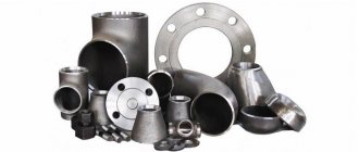
Pipeline supports and hangers, depending on the type, type and design, are made of various fittings, such as a channel, T-bar, angle, pipe, clamp, etc. The type and design of the support or hanger is selected depending on the operating conditions of the pipeline, as well as depending on influence of external conditions. In 1993, a series of regulatory documents was specially developed and put into operation, which included a large number of pipeline supports and hangers. This series consists of several documents, each of which is called OST (industry standard) and has its own serial number. This series of OSTs presents the following types of supports:
- Sliding and fixed supports (supports according to OST 34-10-615-93)
- Welded sliding and fixed supports (supports according to OST 34-10-616-93)
- Sliding clamp supports (supports according to OST 34-10-617-93)
- Fixed clamp supports (supports according to OST 34-10-618-93)
- Roller supports (supports according to OST 34-10-619-93)
- Sliding and fixed supports with a guide clamp (supports according to OST 34-10-620-93)
- Supports for welded bends (supports according to OST 34-10-621-93)
- Tubular supports for steeply curved bends (supports according to OST 34-10-622-93)
- Sliding and fixed supports (supports according to OST 34-10-623-93)
- Welded hangers for horizontal pipelines (hangers according to OST 34-10-724-93)
- Clamp hangers for horizontal pipelines (hangers according to OST 34-10-725-93)
- Hangers with a support beam for pipelines (hangers according to OST 34-10-726-93)
- Welded hangers for vertical pipelines (hangers according to OST 34-10-727-93)
- Clamp hangers for vertical pipelines (hangers according to OST 34-10-728-93)
- Pendants with eye (pendants according to OST 34-10-729-93)
- Pendants with earrings (pendants according to OST 34-10-730-93)
- Pendants with fin (pendants according to OST 34-10-731-93)
- Pendants with traverse (pendants according to OST 34-10-732-93)
- Eyelets with overlay (suspensions according to OST 34-10-733-93)
- Fins with overlay (suspensions according to OST 34-10-734-93)
- Clamps for horizontal pipelines (hangers according to OST 34-10-735-93)
- Clamps for vertical pipelines (hangers according to OST 34-10-736-93)
- Support beams (suspensions according to OST 34-10-737-93)
- Paws with pads (suspensions according to OST 34-10-738-93)
- Threaded rods with coupling (suspensions according to OST 34-10-739-93)
- Suspension mounting blocks (suspensions according to OST 34-10-740-93)
- Rods with an eye (suspensions according to OST 34-10-741-93)
- Articulating rods (suspensions according to OST 34-10-742-93)
- Spring blocks (suspensions according to OST 34-10-743-93)
- Double spring blocks (suspensions according to OST 34-10-744-93)
- Spring support blocks (suspensions according to OST 34-10-745-93)
Thus, the OSTov 34-10-615(745)-93 series divides pipeline supports into 2 main types: pipeline supports and pipeline hangers , which can be fixed, movable, sliding, clamp, suspended, etc. In the figure below, you can see how the supports and hangers of pipelines manufactured according to these OSTs schematically look:
Pipeline supports and hangers:
Depending on what kind of pipeline is to be laid, as well as in what environment and terrain it will be operated, the type of support is selected, which are presented in the series of OSTs above. Pipeline supports and hangers made using this series of OSTs can be divided into the following types:
1) The supports are frameless . Frameless supports can be movable or fixed. At their core, frameless supports are simple clamps, which, depending on whether they should be movable or not, are tightly attached to the pipe or loosely. Movable frameless supports are used in those areas where pipeline displacement occurs due to any temperature deformations. Such supports can move without interfering with pipeline displacements.
2) Body supports . Body supports can be movable or fixed. The geometry of body supports is varied, from simple “boxes” to structures with radius cutouts on the ribs and bent pads welded to them. Also, body supports can be sliding. Sliding supports are a type of movable supports that can move both along their own axis and across it.
3) Housing clamp supports . Body clamp supports can also be movable or fixed. Clamps for body clamp supports can be made of rod or strip (round clamp and flat clamp). Round clamp supports are used exclusively in steel pipelines, while flat clamp supports can also be used in pipelines with different insulations. Also, clamps can be reinforced with stiffeners; such clamp body supports are called yoke supports.
4) Supports for steeply curved bends . The supports of steeply curved bends can be movable or fixed. These supports are mounted under the outlet, which is located in the bend of the pipeline. The geometry of such supports differs depending on what type of bend the support should be installed under, a steeply curved bend or a bent one.
5) Panel supports . Panel supports are used in vertical pipelines. These supports are welded to the pipe, while resting on the floor slabs.
6) Pipeline hangers . Pipeline hangers can be movable or fixed. The hangers can be welded to the pipeline or attached to it using a clamp (pipeline clamp hangers). This type of support may consist of one or two rods that hold the pipeline suspended from the ceiling or beam.
7) Spring blocks . Spring blocks are a type of pipeline hangers that use a spring block. Spring pipeline hangers provide shock absorption of loads and deformations of pipelines and can consist of a single or double block.
The above pipeline supports and hangers can be made of carbon and low-alloy steel. The diameter of the pipeline to which supports of the OSTOV 34-10-615(745)-93 series are applicable varies from 25mm to 1620mm, the pressure cannot exceed 10MPa, and the transporting substance can be at a temperature from -70°C to +450°C.
The weight and other parameters of the pipeline supports and hangers of this series of OSTs depend on its type and design.
Below is an example of the symbol for supports and hangers of a pipeline of the OST 34-10-615(745)-93 series: Support for a pipeline with DN = 108 mm made of carbon steel: Support 108U 03 OST 34-10-615-93
Suspension block with traverse for suspension with a load of 14.7 kN (1500 kgf/cm2): Suspension block with traverse 02 OST 34-10-732-93
If you require other characteristics of pipeline supports and hangers made according to the OST series 34-10-615(745)-93, then you can view them by downloading the OST data from our website.
Using the tables in these OSTs, you can always accurately calculate the cost of transportation costs because they indicate the weight of all existing pipeline supports and hangers according to the OSTov 34-10-615(745)-93 series.
Our company can supply pipeline supports and hangers according to the OSTOV 34-10-615(745)-93 series from steel grades such as steel 20 and steel 09g2s (steel supports, steel hangers).
If you still have questions related to the supports and hangers of the OSTOV 34-10-615(745)-93 pipeline, then you can ask them to our company managers by email [email protected] or by phone +7 (343)361 2377
Pipeline supports: norms and standards
At the moment, standards have been developed at the state level for two categories of such products:
- GOST 14911-82 “Parts of steel pipelines. The supports are movable. Types and main sizes." It applies to movable structures made of steel grades OPB (frameless), OPH (clamp), OPP (movable welded);
- GOST 16127-78 “Parts of steel pipelines. Pendants. Types and main sizes." It applies to pendants designated PM, PG, PMV, PGV.
If we talk about industry standards for assembly units for fastening gas pipeline pipes, then in Moscow there are 2.5 times more of them:
- OST 108.275.24 – pipelines of nuclear power plants and thermal power plants;
- OST 24.125.154 – pipelines for nuclear power plants and thermal power plants made of high-alloy and special steels;
- OST 36-94 – moving elements of technological lines;
- OST 36-104 – steel structures for systems working with media characterized by low temperatures;
- OST 36-146 – series KN, VP, TO, KhB, UP, ShP, TP, KH, KP, TX, TP for diameters 57 – 1420 mm.
There are also three subordinate TU standards relative to GOST. They are used in the production of the models we describe:
- TU 1468-012-04698606 – moving elements of process piping, used at a pressure of 10 MPa, temperatures from -70 °C to +450 °C, pipe diameters of 18–1620 mm;
- TU 1468-002-92040088 – suspension, supports and block modules for pipelines 32 MPa, DN 15–1600 mm;
- TU 1468-001-00151756 – sliding elements for diameters 100–1400 mm, temperatures from -70 °C, pressure 10 MPa.
There are also two series of assembly units of this type:
- 903-10: 4th edition - for structures mounted motionlessly, 5th edition - for movable modifications, 6th edition - for suspensions;
- 903-13: issue 6-95 – pendants, issue 7-95 – fixed elements, issue 8-95 – movable.
The album of drawings T-MM-26-05 includes options for the design of movable and dead structures of PS, ONS and OSS. In the documentation NTS 65-06 you can find working drawings and technical regulations intended for the manufacture of software and non-productive software.
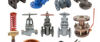
Classification of supports
There are several types of supports that are used depending on the type of pipeline and the need to ensure the absorption of the weight load of the pipeline, or fixation, or free movement of the pipeline along the support platform.
Pipeline supports and their classification:
- movable bearings (sliding, roller, ball, spring, frontal guides). Movable supports supporting the pipeline system do not interfere with pipe displacements, contributing to the natural distribution of temperature deformations.
- fixed supports (welded, clamp, thrust). Fixed pipeline supports are used to install overhead and underground pipelines, and are designed to absorb vertical, horizontal and vibration loads from pipelines.
Depending on the operating conditions, the supports are made of various materials. In areas with a temperate climate, according to GOST 15150-69, the main material is carbon steel. In the case of using supports in areas with cold climates in accordance with GOST 15150-69, structural low-alloy steel is used for manufacturing.
There are a large number of regulatory documents (Series 5.903-13 Issue 8-95 Mobile pipeline supports, Series 5.903-13 Issue 7-95 Fixed pipeline supports) according to which pipeline supports and hangers are manufactured. As a rule, they specify the types of pipelines for which these supports are intended, the dimensions of the supports for the pipelines, the permissible loads on the supports, including the friction coefficients of the sliding supports.