GOST 6357 dated '81 applies to pipe threads, which are mainly used for joining fittings, pipes and fittings. Internal cylindrical and external conical threads, as well as simply cylindrical forms, can be connected. GOST establishes the required dimensions, tolerances and profile parameters. Taper threads must comply with standard 6211.
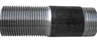
Threads are often used to connect metal pipes, and they must be cut in strict accordance with GOST
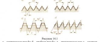
Parameters of tapered pipe thread
This type of connection is indicated exclusively in inches. Values are indicated in whole and fractional parts. The profile of a tapered pipe thread differs from its standard inch counterpart. The apex angle is 55° in the first case and 60° in the second. In some cases, connections of both types are allowed. The conditions are defined in GOST 6211–81. § 4.7 says that in this case it is possible to use an external conical pipe thread in conjunction with a cylindrical internal thread. The nominal values must match. For example, the diameter of 1½ should be the same for both parts. The internal pipe inch tapered thread is not connected to the external cylindrical element.
If the designation contains the letters LH, it means the direction of rotation is left. Taper - 1° 47′ 24″. This value gives a ratio of thread length to diameter difference of 1:16.
This parameter is the same for all types of tapered pipe threads, but the pitch is significantly different. Historically, it has been measured in threads per inch. But in the process of production evolution, some values do not correspond to the specified data. Therefore, all inch threads today are deciphered in the usual European standards. The metric measurement system is much more convenient to use.
Below are the correspondence between inch values and analogues in mm:
- ⅛ - 28 (number of threads per inch), 0.907 mm;
- ¼ - 19, 1.337 mm;
- ⅜ - 19, 1.337 mm;
- ½ - 14, 18.14 mm
- ¾ - 14, 18.14 mm
- 1 - 11, 23.09 mm
- 1¼ - 11, 23.09 mm
- 1½ - 11, 23.09 mm
- 2 - 11, 23.09 mm
Tapered pipe threads have three diameters: external, internal and middle. The connection drawing is made in the form of a trapezoid. Its base is an external thread, the top is internal. The average is calculated mathematically. It roughly corresponds to the dimensions of a regular cylindrical inch thread. This is important to know when combining different types of connections. That is, when a conical part is screwed into a regular inch thread, the connection becomes loose at the beginning of rotation. Towards the middle of the length it becomes denser, further movement is carried out with increasing tension. Advantages of a cone is often used in standard connections with loose internal threads. If the part is worn out and the internal hole becomes larger than normal, then the cylindrical element can be replaced. The angle of the cone compensates for the slackness along the diameter.
Download GOST 6211-81
You should know that when preparing parts for processing, allowances must be taken into account. When making a cone on the incoming part, they are guided by the outer diameter value according to the table. Then they check the length of the workpiece and only then make the required slope. On a lathe, the angle is set on the upper carriage of the support. The second option is to use a shaped cutter. In both cases, you will have to do manual adjustment, and it is difficult to accurately align the cutting tool, so be sure to check the angle with a special gauge.
The profile apex angle of 55° was not chosen by chance. This guarantees better sealing of the connection. When tightening, the parts grind together with slight creasing of the profile. However, using force during assembly is not recommended. The taper of the parts causes the load vector to be directed outward. The part may simply break due to excessive force. Especially if the thickness of the element with internal thread is small. It is not recommended to use the technology on thin-walled brass and aluminum parts. This must be remembered when it is decided to combine conical pipe and cylindrical pipe threads, which were not calculated during production for this type of load.
MAIN DIMENSIONS
2.1. The designation of the thread size, pitches and nominal values of the outer, middle and inner thread diameters must correspond to those indicated in the drawing. 1 and in table. 2.
table 2
Dimensions in millimeters
| Thread size designation | Step P | Thread diameters | |||
| Row 1 | Row 2 | d = | d 2 = | d 1 = | |
| 1/16 | — | 0,907 | 7,723 | 7,142 | 6,561 |
| 1/8 | 9,728 | 9,147 | 8,566 | ||
| 1/4 | — | 1,337 | 13,157 | 12,301 | 11,445 |
| 3/8 | 16,662 | 15,806 | 14,950 | ||
| 1/2 | 1,814 | 20,955 | 19,793 | 18,631 | |
| 3/4 | 5/8 | 22,911 | 21,749 | 20,587 | |
| 26,441 | 25,279 | 24,117 | |||
| 7/8 | 30,201 | 29,039 | 27,877 | ||
| 1 | 11/8 | 2,309 | 33,249 | 31,770 | 30,291 |
| 37,897 | 36,418 | 34,939 | |||
| 11/4 | 41,910 | 40,431 | 38,952 | ||
| 11/2 | 13/8 | 44,323 | 42,844 | 41,365 | |
| 47,803 | 46,324 | 44,845 | |||
| 13/4 | 53,746 | 52,267 | 50,788 | ||
| 2 | 2¼ | 59,614 | 58,135 | 56,656 | |
| 65,710 | 64,231 | 62,752 | |||
| 21/2 | 75,184 | 73,705 | 72,226 | ||
| 3 | 23/4 | 81,534 | 80,055 | 78,576 | |
| 87,884 | 86,405 | 84,926 | |||
| 31/4 | 93,980 | 92,501 | 91,022 | ||
| 31/2 | 33/4 | 100,330 | 98,851 | 97,372 | |
| 106,680 | 105,201 | 103,722 | |||
| 4 | 113,030 | 111,551 | 110,072 | ||
| 5 | 41/2 | 125,730 | 124,251 | 122,772 | |
| 138,430 | 136,951 | 135,472 | |||
| 6 | 51/2 | 151,130 | 149,651 | 148,172 | |
| 163,830 | 162,351 | 160,872 | |||
When choosing sizes, the first row should be preferred to the second.
2.2. Numerical values of diameters d
2 and
d
1 are calculated using the following formulas
| d 2 = | (1) |
| d 1 = | (2) |
Numerical values of diameter d
established empirically.
Methods for cutting tapered pipe threads
Unlike standard cylindrical threads, where the diameter is the same throughout the entire length of the part, conical threads are made taking into account the characteristics of the connection. It is performed on machines that allow the movement of the caliper at a given angle, or with the help of metalworking tools: dies and taps. When cutting tapered threads, it is important to accurately observe the direction of movement and position of the tool. Control the process using a square. Deviations seriously degrade the quality and the thread can no longer be used in critical connections. The working tool may consist of a set of taps and dies with the numbers indicated on them.
How to cut threads yourself? First of all, it is necessary to securely fix the part in a vice in such a way as to ensure access to the measuring square. If you have a drilling machine, then it is enough to clamp it without distortions. When using a drill, it is more difficult to control the angle. You can use additional devices, for example, a jig or a guide coupling. Particular care should be taken when finishing passes with a conical drill or reamer. An accurately made hole will allow the tap to make the correct entry. When the slope of the outer cone of the part corresponds to the specified angle, the die will easily self-orient along it and the thread will be of high quality.
Slicing equipment
In practice, an ordinary mechanic does not often have to make a conical thread, if the specifics of production are not related to the manufacture of parts with this type of connection. A home master encounters this operation even less often. A table for determining diameters will be an assistant in your work.
| Size in inches | Hole diameter, mm | Drilling depth, mm | |
| dc | do | ||
| ⅛ | 8,10 | 8,57 | 15 |
| ¼ | 10,80 | 11,45 | 20 |
| ⅜ | 14,30 | 14,95 | 24 |
| ½ | 17,90 | 18,63 | 29 |
| ¾ | 23,35 | 24,12 | 31 |
| 1 | 29,35 | 30,29 | 37 |
| 1¼ | 37,80 | 38,95 | 40 |
| 1½ | 43,70 | 44,85 | 42 |
| 2 | 55,25 | 56,66 | 44 |
The largest diameter of the cone is denoted by do, and the smallest by dc. To facilitate the entry of the tool, a chamfer is made. It is difficult and time-consuming to make a tap in a cylindrical hole. To reduce labor intensity and speed up the operation, use conical drills and reamers of the required size. If the tool is complete, then first take a tap or die with number 1. This is rough cutting. Then they pass with tool No. 2. Sometimes a set may contain 3 types of taps. In non-ferrous metals, tapered threads can be made in one pass if cutting fluids are used. When working with steel, it is advisable to go through the hole sequentially with all taps.
The direction of the cone is indicated on the dies. If there is no corresponding icon, or there is an incomprehensible abbreviation, then you need to measure it on both sides with a caliper.
You can also see the cone from the jaws for internal measurements. It is enough to insert them inside and you will see the slope on the die relative to the parallel jaws of the caliper. Conical dies are wider than regular dies because they must completely cover the length of the workpiece. They are harder to work with. The load is distributed over the entire cutting surface, so use a powerful wrench with long handles, or extend them to create a lever. Designated machine die 2684-0015, manual 2684-0015r. All characteristics are specified in GOST 6228-80. The tap has the abbreviation 2680-0016. Technical characteristics are described in GOST 6227-80.
Conical connections are used in critical components, so the requirements for surface finish are high. This can only be achieved by using high-quality cutting fluids. The choice of compositions is wide. But if professional materials are not at hand, then at home you can use animal fat for work. According to its characteristics, it is excellent for this purpose. Many experienced masters often use it in their practice. It guarantees good glide and high-quality cutting of metal without chipping.
Download GOST 6227-80
Download GOST 6228-80
The cutting tool is made of tool, high-speed steels. GOST specifies the recommended service life of dies and taps. It is calculated for a tool made of R6M5 alloy using workpieces made of steel 45. The die must be guaranteed to process from 125 (more than 1 inch) to 225 (less than an inch) external threads that meet the requirements of GOST. Accordingly, if more durable alloys of parts are used in the work, the service life decreases. To check the quality of processing, geometric dimensions and compliance with the profile, special templates are used - calibers. The same devices are used when sharpening cutters for lathes.
MAXIMUM DEVIATIONS FOR THE CUT OF THREAD CAP AND FOOT THREAD
1. This appendix contains information on the maximum cut deviations (dimensions) of the tops and bottoms of external and internal threads, which are the initial ones when designing a thread-forming tool and are not subject to mandatory control, unless specifically stated.
2. Maximum size deviations are shown in the drawing and table.
es is the upper deviation of the cut of the top and bottom of the external thread; ES - upper deviation of the cut of the top and bottom of the internal thread; ei is the lower deviation of the cut of the top and bottom of the external thread; EI - lower deviation of the cut of the top and bottom of the internal thread
Crap. 3
| Cutting off the top of the external and internal threads | Cutting the root of external and internal threads | ||
| Prev. off, µm | |||
| es = ES | ei = EI | es = ES | ei = EI |
| +75 | +25 | -50 |
INFORMATION DATA
1. DEVELOPED AND INTRODUCED by the Ministry of Machine Tool and Tool Industry
2. APPROVED AND ENTERED INTO EFFECT by Resolution of the USSR State Committee on Standards dated December 30, 1981 No. 5790
3. INSTEAD GOST 6357-73
4. The standard fully complies with ST SEV 1157-78
5. REFERENCE REGULATIVE AND TECHNICAL DOCUMENTS
| Designation of the referenced technical document | Item number |
| Introductory part, 1.2, 3.6, 4.4 |
6. REISSUE
| 1. Profile. 1 2. Main dimensions.. 1 3. Tolerances. 2 4. Thread designations.. 4 Application. (informative) Limit deviations of cutting the tops and bottoms of the thread.. 4 |
How are connections of threaded parts designated?
All characteristics of conical pipe threads are specified in GOST 6211–81. Domestic standards are compatible with foreign analogues: ISO R7, DIN 2999, BS 21, JIS B 0203. This type of thread is designated by the English letters R (external) and Rc (internal). GOST describes the profile, dimensions and tolerances of the connection. The detailed drawing shows the characteristic features of the connection. Additional applications regulate the preparation of parts for work. A summary table of the main parameters of pipe threads is the basis for controlling the quality and dimensions of the product.
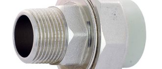
Particular attention is paid to how the connection designation is made. If two types of thread are used, they are written as a fraction. The numerator is the inner part and the denominator is the outer part of the compound. For example, Rp/R 3/4 LH. This means that the threads are left-handed, three-quarters of an inch nominal, the internal cylindrical and the external conical pipe. The combination of different types is often used in repair practice. This restores the functionality of plumbing and gas appliances. Tapered threads are preferable where reliable sealing is needed.
What else is worth paying attention to
Vapor barrier “isospan”: marking, scope of application, installation rules
Today there is such a problem as the discrepancy between what is written and reality. The same applies to the issue under consideration. Here's the thing. For example, there is a designation for a screw joint as ½ inch. Logically, converting this figure to the metric system, you should get a hole with a diameter of 12.7 mm. But in fact, the pipe says 20.95. This discrepancy occurs because the inch thread specifies the bore, not the outer diameter.
If you add wall thickness, you can end up with that overestimated number in the metric system. Conventionally, we can assume that one inch of pipe is approximately 33.25 mm, that is, the standard 25.4 and plus two more walls of 3.92. It is advisable to take this into account when choosing the required material.
Conclusion: The text presents only two types - BSPP and BSPT, respectively, which are the main ones. In addition to them, there are types such as NPSM and NPT. There is also one that is designed for parts that are constantly twisting and unwinding. Its designation is Kr. There is also trapezoidal, rectangular and many others.
How to find out the diameter of a pipe? Measure!
In most cases, when purchasing, it is enough to look at the label or the seller. But it happens that you need to repair one of the communication systems by replacing pipes, and initially it is not known what diameter the already installed ones have. There are several ways to determine the diameter, but we will list only the simplest ones:
- Arm yourself with a tape measure or a tape measure (this is how women measure their waist). Wrap it around the pipe and record the measurement. Now, to obtain the desired characteristic, it is enough to divide the resulting figure by 3.1415 - this is the number Pi.
- After obtaining the outer diameter, you can find out the inner one. Only for this you need to know the thickness of the walls (if there is a cut, just measure with a tape measure or other device with a millimeter scale). Let's assume that the wall thickness is 1 mm. This figure is multiplied by 2 (if the thickness is 3 mm, then it is also multiplied by 2 in any case) and subtracted from the outer diameter (18.85- (2 x 1 mm) = 16.85 mm)
.It’s great if you have a caliper at home. The pipe is simply grabbed by the measuring teeth. We look at the required value on a double scale.
Which pipe is considered small - medium - large?
Even in serious sources I have seen phrases like: “We take any pipe of average diameter and...”, but no one indicates what this average diameter is. To figure it out, you should first understand what diameter you need to focus on: it can be internal or external. The first is important when calculating the transport capacity of water or gas, and the second is important for determining the ability to withstand mechanical loads.
External diameters:
- From 426 mm is considered large;
- 102-246 is called average;
- 5-102 is classified as small.
As for the internal diameter, it is better to look at the special table (see above).