All ALSO ball valves are tested for tightness class “A” according to GOST 33257-2015.
GOST 24856-2014 “Pipeline fittings. Terms and definitions" defines the following concepts related to tightness:
Tightness is the ability of fittings and its individual elements and connections to prevent gas or liquid exchange between separated cavities.
Sealing is a process of interaction between elements, assemblies and parts of fittings, in which a connection is formed that excludes the possibility of penetration of media through it in any direction or limits this penetration to a given degree of tightness.
The tightness of the shutter is the property of the shutter to prevent gas or liquid exchange between the cavities separated by the shutter.
The valve tightness standard Q is the maximum permissible leakage in the valve valve.
A leak:
- Penetration of the medium from a sealed product under the influence of a pressure difference;
- The volume of medium per unit time passing through a closed valve valve under the influence of a pressure difference.
The tightness class of the valve (tightness class) is a seal characteristic assessed by the permissible leakage of the test medium through the valve.
The degree of tightness is a quantitative characteristic of the tightness of the fittings, assessed depending on the purpose and danger of the working environment and the potential severity of consequences in case of loss of tightness.
Test media in accordance with GOST 9544-2015 “Pipeline fittings. Tightness standards"
shutters:
- Water (which may contain a corrosion inhibitor), kerosene or any other liquid whose viscosity does not exceed that of water;
- Air or other gas (eg nitrogen, natural gas, freon). The air must be dried to a dew point temperature that prevents moisture loss during throttling.
The type of test environment is established in the technical specifications and selected depending on the danger of the working environment:
- For fittings for liquid media that are not classified as hazardous substances, the test medium is water or air;
- For fittings for gaseous media, as well as liquid media related to hazardous substances, the test medium is air. Water tests are allowed upon agreement with the customer;
- For nuclear power plant fittings, the test medium is water or air.
Tightness standards for pipeline fittings
Determined by GOST 9544-2015 “Pipeline fittings. Valve tightness standards"
. The tightness standard of the valves is determined depending on the nominal diameter DN and the tightness class according to the table below:
- when testing with water pressure Risp=1.1PN - for all nominal pressures PN;
- when tested with air: Risp = 0.6 MPa - for PN ≥ 6;
- Risp = PN - for PN < 6
Table - Norms and tightness classes of shut-off and check valves
| Leakage class | Valve tightness standard Q for test environment | |||
| water at Risp=1.1pn | air at Risp=0.6 MPa | |||
| Q, mm3/s | Q, cm3/min | Q, mm3/s | Q, cm3/min | |
| A | No visible leaks during the test time | |||
| AA | 0.006 dn | 0.0004 dn | 0.18 dn | 0.011 dn |
| IN | 0.01 dn | 0.0006 dn | 0.30 dn | 0.018 dn |
| WITH | 0.03 dn | 0.0018 dn | 3.00 dn | 0.18 dn |
| SS | 0.08 dn | 0.0048 dn | 22.30 dn | 1.30 dn |
| d | 0.10 dn | 0.006 dn | 30 dn | 1.80 dn |
| e | 0.30 dn | 0.018 dn | 300 dn | 18.0 dn |
| her | 0.39 dn | 0.023 dn | 470 dn | 28.2 dn |
| f | 1.0 dn | 0.060 dn | 3000 dn | 180 dn |
| g | 2.0 dn | 0.12 dn | 6000 dn | 360 dn |
Why do you need tightness control?
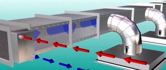
Air ducts are used:
- in heating systems;
- in aspiration systems for air suspensions (forced outflow);
- in smoke removal systems.
Note! The air duct is designed for a specific room, taking into account its spatial configuration and practical purpose.
The tightness of the ventilation determines the efficiency of the air duct. For comparison, they often use the analogy of a leaky hose of a household vacuum cleaner - with such a defect, the device works hard, but the debris remains in place.
Modern standards for installing air ducts, in addition to material requirements, also focus on tightness. This is officially established by SNiP 3.05.01-85. In addition to the technical characteristics, SNiP 3.05.01-85 also identifies the reasons for the strict requirements for the absence of air leaks in the ventilation system.
The need to control the tightness of air ducts is due to the following reasons:
- Ventilation that has leaks cannot provide the necessary sanitary requirements for air quality in a domestic or industrial premises. An example of the consequences of loss of ventilation tightness is carbon monoxide poisoning in gasified houses of old construction. Repairing an air duct is technically more difficult and costs more than high-quality installation and measures for checking tightness.
- To comply with sanitary standards in rooms with forced ventilation (modern industrial, administrative, office and other public buildings), it is necessary to operate the system at maximum capacity. This results in increased energy intensity, increased cost of the production process, and premature wear of equipment.
- In unheated buildings, loss of air duct tightness leads to the formation of condensation inside the communications. This is fraught with failure of the ventilation system and damage.
Note! In practice, it is better to entrust checking the tightness of the ventilation system to a third-party organization, and not to the construction company that installed it.
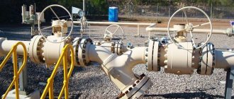
Rules for installing valves on a pipeline
Installation of fittings on main and industrial pipelines can only be carried out by qualified specialists who have permission to perform this type of work. When installing valves, you must follow certain installation rules, depending on the type and purpose of the devices:
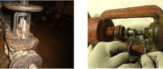
- Shut-off valves can only be dismantled if there is no working medium in the system. It is necessary to thoroughly clean the pipe installation site from dirt, scale and deposits.
- Before installation, it is necessary to check the quality of the flange connection for cracks, chips, scratches and other visible defects.
- Installation of shut-off valves is possible only on a straight section of the main line in order to avoid distortions and bends of the system, which can lead to stress and leaks. Installation of heavy components is impossible without the use of rigid supports.
- Great forces should not be applied to the flywheels due to the possibility of damage to the unit and the appearance of cracks.
- When installing the fittings, you must not allow them to fall, cause mechanical damage, or be struck.
Products are delivered in special packaging that complies with GOST 9.014, GOST 15150 with a degree of protection VU-0 or VU-1.
Types of pipeline valves by valve design
Wedge valves
This type of pipeline fitting has a wedge-shaped shut-off element located between two inclined surfaces. The principle of operation is simple - the wedge moves perpendicular to the spindle axis, blocking the flow of the working medium. There are several types of dampers based on the rigidity of the wedge: with a rigid, rubberized, double-sided and elastic wedge.
- Products with a rigid wedge have a simple design, high reliability and tightness. However, the locking wedge assembly requires careful adjustment of the wedge and seals, otherwise the tightness will be compromised. The wedge is mounted on the spindle using hinges. During operation, it moves along the housing guides. This allows the use of such products at increased pressure drops. The main disadvantage is the danger of the system jamming due to temperature changes, rapid wear of seals, and complicated repairs.
- Double-disc wedge valves have in their design two disks placed at an angle and connected by an expansion element. This ensures self-leveling of the assembly when adjacent to the seats, eliminates the possibility of jamming and provides increased tightness. Such valves have a more complex design and high cost. However, their working life is significantly longer, the wear of seals is lower, and no force is required to close the passage of the medium. Double wedge gate valves have a sliding spindle and are equipped with O-ring seals for higher sealing of DN.
- Gate valves with an elastic wedge are a type of double-disc model. They have a drive divided in two, in which a deformable spring element is placed. Thanks to this design, the seals can move at an angle to each other, which increases the tightness of contact with the seat. Such fittings do not require adjustment and do not jam during operation due to temperature changes. However, the wedge wears out quickly.
Gate valves
This type of valve has a parallel arrangement of the butterfly valve and the seat. The locking unit works as follows: the gate mechanism is lowered, reliably closing the conditional passage under the influence of pressure. This is the simplest type of valve, used in systems where high tightness is not required. Shows excellent performance in sewer pipelines and slurry pipelines. Easy to maintain and repair.
Hose valves
This type of fittings is used least often in pipelines with small diameters. Area of use: slurry pipelines and systems with an abundance of impurities and sludge. They have an unusual design of the locking assembly, in which there are no sealing seats. The valve element itself is a flexible hose that is pinched using a rod. Hose valves are resistant to corrosion and can be used to transfer viscous and chemically aggressive media.
Types of valves based on body material
Gate valves are made of black and stainless steel, aluminum and cast iron. Let's look at the design of the fittings on the most popular models.
Steel valve 30s41nzh
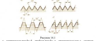
First you need to understand the markings (according to GOST 466-75):
- «30» - an indication that there is a valve in front of us.
- “c” is the body material, in our case steel.
- «41» - type of valve with manual drive. (If “41” was preceded by the number “5”, then we would be talking about controlling the gearbox, “9” - the electric drive).
- “NZ” is a type of seal on the wedge discs and seat surfaces. Stainless steel.
Let's move on to the main materials for manufacturing DSE.
- The cover and body are made of carbon steel by casting.
- Spindle material - steel 20Х13.
- The disc and flywheel are also made of carbon steel.
- The drive nut is brass. The most common option is LS59-1. This material is characterized by increased resistance to mechanical damage due to friction.
- Wedge seals are steel 13Х25Т. This material contains a lot of chromium and is wear-resistant and corrosion-resistant. Titanium increases the service life of the product.
- The seals on the body rings are steel 08Х21Н10Гб. This material contains 10% nickel and 20% chromium. The unit is highly wear resistant.
In addition to the above-mentioned materials, 20s41nzh valves are equipped with a gland seal made of thermally expanded graphite (TEG). This material is available in the form of a cord or a ring. It is installed in the system, preventing the passage of the working medium through the seal.
There are several variations of TRGs used in pipeline fittings:
- TRG-100L is a material reinforced with lavsan thread.
- TRG-100LF - with reinforcement with lavsan thread and additional fluoroplastic impregnation.
- TRG-101N - reinforced with stainless wire.
- TRG-102S - glass fiber reinforcement.
TEG ensures increased tightness of the product due to its chemical and physical properties and the ability not to change configuration under the influence of temperature.
Steel valves are used everywhere in main and industrial pipelines carrying water, gas, petroleum products, oil, chemicals and other media to which the material of the valve elements is corrosion-resistant. Some equipment models can be used to transport steam or sea water.
Seals are applied to the wedge and body surfaces using laser cladding or arc welding. Both of these methods involve mixing the weld material with the base material at high temperature. After surfacing, it is necessary to perform manual or automatic scraping to determine the geometric parameters of the wedge assembly and adjust the system elements to each other. This is necessary to increase the tightness class of the fittings.
Cast iron valve 30h39r
This type of pipeline shut-off valve is made from gray or ductile iron. They are used to transfer liquid media and gas in main systems.
Basic materials of nodes:
- The body, cover and wedge are gray cast iron.
- Spindle - steel 20Х13.
- Drive sleeve - brass, bronze.
The wedge seal is made of elastic material EPDM (ethylene propylene rubber). It is distinguished by enhanced physical and chemical properties, due to which the valve practically does not collapse under the influence of mechanical loads. It has corrosion resistance and the ability to maintain geometry at high temperatures.
Another option is fluorine rubber (used in acidic environments) or organosilicon compounds (if there is a risk of large temperature changes).
Types of valves by spindle assembly
Products with a retractable spindle are distinguished by a greater building height due to the spindle extended outside the body. When opening the valve, it needs to come out of the valve to a length greater than the diameter of the pipe. This must be taken into account when designing the installation location of the product on the pipeline.
- The main advantage is that the spindle does not come into contact with the working environment, thereby increasing the service life of the unit, its corrosion resistance and maintainability.
- Disadvantages - large construction height, weight.
Valves with a non-rising spindle have a running unit placed inside the body, which leads to direct contact of the working medium with the elements of the spindle unit. Such products are mounted on pipelines transporting water and non-aggressive working media.
- The main advantage is the low construction height and the possibility of installation in hard-to-reach places.
- Disadvantages - the inability to control the condition of the stuffing box assembly during operation, complex repairs (dismantling and disassembling of the fittings is necessary).
Gate valves with rising and non-rising stems have different operating principles. The first ones make translational movements up and down to block the flow of the working medium. In the second case, the spindle rotates around its axis, and the drive nut is installed in the wedge valve.
Density classes
All ventilation and smoke exhaust systems are characterized by the following air duct density classes:
- dense (P);
- normal (N).
Tight air ducts are characterized by increased tightness of connecting joints, during installation of which a sealant and a tight, durable lock must be used. They can be used for powerful pumping equipment with operating pressure from 1.4 kPa. They are used in the following types of premises:
- Category A - with the presence of flammable gases and flammable liquids with a flash point of up to +280C, at which an excess pressure above 5 kPa occurs.
- Category B - the presence of flammable fibers and dust in the air, the flash point of which does not exceed +280C, and the explosion pressure is from 5 kPa.
Class H made of galvanized steel is most common when installing ventilation systems in residential buildings, office and administrative premises, as well as in warehouses with a fire hazard level of “G” or “B”.
The main difference between normal and tight joints is the reduced requirements for the tightness of joints, as well as the permissibility of using rubber seals, and not just silicone grease.
Types of valves for installation on a pipe
There are welded products that have pipes with cut edges for welding. In diameter they are equal to the diameter of the pipeline. The insertion is made using argon arc welding.
The flange type of connection is the most common method of installing valves on a pipe. Such products have flanges at the ends of the pipes. This allows you to create a detachable connection with the mating flanges of the pipeline, ensuring quick installation/dismantling of the valves.
Coupled valves are connected by screwing into the pipeline. They are used only in small diameter systems with DN up to 50 mm.
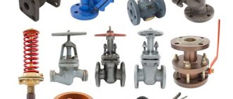
Types of valves for pipelines
Valves differ in many characteristics:
- designs;
- drive type;
- material of the main parts (body, spindle, etc.);
- product dimensions;
- type of connection to the pipe, connecting dimensions;
- operating conditions (working environment, temperature);
- climatic conditions (execution);
- tightness class;
- wedge gate designs;
- bore diameter Du;
- the type and nature of the sealing surfaces;
- maximum pressure in the system.
The main design elements include:
- Metal case with lid. They are made of black steel, stainless alloy, aluminum or cast iron. There are brass products. The body is the main element of the valve, which is installed in the main line. The cover is needed to adjust the position of the locking unit.
- Locking mechanism , shaped like a wedge, gate or disc. It is made of metal and is complemented by seals made of elastic materials that increase the tightness of the system.
- Drive mechanism that controls the movement of the damper. There are manual valves with a flywheel (on a retractable or non-retractable rod), automatic, controlled by a mechanical gearbox or an electric, pneumatic, or hydraulic drive.
Based on the method of body production, a distinction is made between cast, forged, welded and forged-welded valves.