Formulation of the problem
Hydraulic calculations when developing a pipeline project are aimed at determining the diameter of the pipe and the pressure drop of the carrier flow. This type of calculation is carried out taking into account the characteristics of the structural material used in the manufacture of the pipeline, the type and number of elements that make up the pipeline system (straight sections, connections, transitions, bends, etc.), productivity, physical and chemical properties of the working environment.
Many years of practical experience in operating pipeline systems have shown that pipes with a circular cross-section have certain advantages over pipelines with a cross-section of any other geometric shape:
- the minimum ratio of perimeter to cross-sectional area, i.e. with equal ability to ensure media consumption, the cost of insulating and protective materials in the manufacture of pipes with a cross-section in the form of a circle will be minimal;
- the round cross-section is most advantageous for moving a liquid or gaseous medium from the point of view of hydrodynamics; minimal friction of the carrier against the pipe walls is achieved;
- the circular cross-sectional shape is maximally resistant to external and internal stresses;
- The process of making round pipes is relatively simple and affordable.
The selection of pipes by diameter and material is carried out on the basis of specified design requirements for a specific technological process. Currently, pipeline elements are standardized and unified in diameter. The determining parameter when choosing a pipe diameter is the permissible operating pressure at which the pipeline will be operated.
The main parameters characterizing the pipeline are:
- conditional (nominal) diameter – DN;
- nominal pressure – PN;
- working permissible (excessive) pressure;
- pipeline material, linear expansion, thermal linear expansion;
- physical and chemical properties of the working environment;
- complete set of pipeline system (branches, connections, expansion compensation elements, etc.);
- pipeline insulation materials.
The nominal diameter (bore) of a pipeline ( DN) is a conventional dimensionless value that characterizes the flow capacity of a pipe, approximately equal to its internal diameter. This parameter is taken into account when adjusting related pipeline products (pipes, bends, fittings, etc.).
The nominal diameter can have values from 3 to 4000 and is designated: DN 80 .
The nominal diameter, by numerical definition, approximately corresponds to the actual diameter of certain sections of the pipeline. Numerically, it is chosen in such a way that the throughput of the pipe increases by 60-100% when moving from the previous nominal passage to the next. The nominal diameter is selected according to the value of the internal diameter of the pipeline. This is the value that is closest to the actual diameter of the pipe itself.
Nominal pressure (PN) is a dimensionless quantity characterizing the maximum pressure of the working medium in a pipe of a given diameter, at which long-term operation of the pipeline is possible at a temperature of 20°C.
The nominal pressure values have been established based on long-term practice and operating experience: from 1 to 6300.
The nominal pressure for a pipeline with given characteristics is determined by the pressure closest to the one actually created in it. At the same time, all pipeline fittings for a given main must correspond to the same pressure. The pipe wall thickness is calculated taking into account the nominal pressure value.
Basic properties
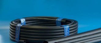
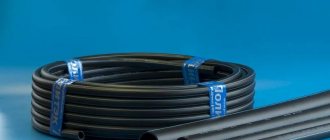
HDPE materials are hard and very durable, flexible and durable. This means that pipes made from them are wear-resistant and capable of withstanding significant loads: they are resistant to stretching, compression, rupture, bend well and are not afraid of cracks.
Technical indicators
- Possible melting temperature range – from -60 to +120 0C, optimal operation from 0 to +40 0C,
- The maximum pressure inside the pipe can reach 16 - 20 atm,
- HDPE pipes are inert to transported substances and do not change their qualitative composition (for example, they do not change the taste and smell of water),
- Do not allow liquids and gases to pass through their structure,
- Resistant to corrosion in any form,
- Resistant to biological factors (not destroyed by microorganisms),
- They have high dielectric properties, therefore they are not susceptible to stray currents,
- Smooth from the inside, which ensures they are less clogged with suspensions from the contents,
- Absorbs noise emitted by liquids as they move through the system,
- They have a very long service life - about 50 - 80 years.
INTERESTING! Even with the initial strength of materials, their production includes mandatory tests for compliance with specific technical indicators for each type and grade of products: resistance to tearing and high temperatures, pressure increase, etc.
Design features
In addition to the difference in material quality, pipes made of low-density polyethylene differ in design - diameters and wall thickness, which directly affects their properties and possibilities of use. Their markings indicate these values and their ratio in the form of the SDR index, which is the strength characteristic of the pipe and an indicator of the height of possible mechanical loads for it.
Currently, HDPE pipe products are produced with diameters from 10 to 1600 mm and wall thicknesses from 2 to 60 mm, for which the following content pressure is permissible:
| Pressure for PE-80 | 3.2 atm | 5 atm | 6 atm | 7.5 atm | 10 atm | 12.5 atm | 16 atm |
| Pressure for PE-100 | 4 atm | 6 atm | 8 atm | 9.5 atm | 12.5 atm | 16 atm | 20 atm |
| Pipe diameter (external), mm | Wall thickness, mm | ||||||
| 20 | — | — | — | — | — | 2,0 | 2,3 |
| 32 | — | — | — | 2,0 | 2,4 | 3,0 | 3,6 |
| 40 | — | — | 2,0 | 2,4 | 3,0 | 3,7 | 4,5 |
| 50 | — | 2,0 | 2,4 | 3,0 | 3,7 | 4,6 | 5,6 |
| 63 | — | 2,5 | 3,0 | 3,8 | 4,7 | 5,8 | 7,1 |
| 75 | 2,0 | 2,9 | 3,6 | 4,5 | 5,6 | 6,8 | 8,4 |
| 90 | 2,2 | 3,5 | 4,3 | 5,4 | 6,7 | 8,2 | 10,1 |
| 160 | 4,0 | 6,2 | 7,7 | 9,5 | 11,8 | 14,6 | 17,9 |
| 225 | 5,5 | 8,6 | 10,8 | 13,4 | 16,6 | 20,5 | 25,2 |
| 315 | 7,7 | 12,1 | 15,0 | 18,7 | 23,2 | 28,6 | 35,2 |
| 400 | 9,8 | 15,3 | 19,1 | 23,7 | 29,4 | 36,3 | 44,7 |
| SDR 41 | SDR 26 | SDR 21 | SDR 17 | SDR 13-14 | SDR 11 | SDR 9 |
IMPORTANT! Products with diameters up to 160 mm are most often supplied in coils or coils up to 500 meters long, although they can also be produced in the form of measured lengths. Pipes with a diameter of more than 160 mm are produced only in measured sections.
Basic principles of hydraulic calculation
The working medium (liquid, gas, steam) carried by the pipeline being designed, due to its special physical and chemical properties, determines the nature of the flow of the medium in this pipeline. One of the main indicators characterizing the working medium is dynamic viscosity, characterized by the coefficient of dynamic viscosity - μ.
Engineer-physicist Osborne Reynolds (Ireland), who studied the flow of various media, conducted a series of tests in 1880, as a result of which the concept of the Reynolds criterion (Re) was derived - a dimensionless quantity that describes the nature of fluid flow in a pipe. This criterion is calculated using the formula:
The Reynolds criterion (Re) gives the concept of the ratio of inertial forces to viscous friction forces in a fluid flow. The value of the criterion characterizes the change in the ratio of these forces, which, in turn, affects the nature of the carrier flow in the pipeline. It is customary to distinguish the following modes of liquid carrier flow in a pipe depending on the value of this criterion:
- laminar flow (Re<2300), in which the carrier-liquid moves in thin layers that practically do not mix with each other;
- transition mode (2300
- turbulent flow (Re>4000) is a stable mode in which at each individual point of the flow there is a change in its direction and speed, which ultimately leads to equalization of the flow speed throughout the volume of the pipe.
The Reynolds criterion depends on the pressure with which the pump pumps the liquid, the viscosity of the media at operating temperature and the geometric dimensions of the pipe used (d, length). This criterion is a similarity parameter for fluid flow, therefore, using it, it is possible to simulate a real technological process on a reduced scale, which is convenient when conducting tests and experiments.
When carrying out calculations and calculations using equations, part of the given unknown quantities can be taken from special reference sources. Professor, Doctor of Technical Sciences F.A. Shevelev developed a number of tables for accurately calculating the pipe capacity. The tables include the values of parameters characterizing both the pipeline itself (dimensions, materials) and their relationship with the physical and chemical properties of the carrier. In addition, the literature provides a table of approximate values of the flow rates of liquid, steam, and gas in pipes of various sections.
SNiP 2.04.02-84: Appendix 10 - Hydraulic calculation of pipelines
General provisions Estimated water flows and free pressures estimated water flows Sources of water supply Schemes and systems of water supply Water intake structures Water treatment Pumping stations Water pipelines, water supply networks and structures on them Water storage tanks Sanitary protection zones Cooling water recycling systems Equipment, fittings and pipelines Electrical equipment, process control , automation and control systems Construction solutions and structures of buildings and structures Additional requirements for water supply systems in special natural and climatic conditions Appendix 1 Appendix 2 Appendix 3 Appendix 4 Appendix 5 Appendix 6 Appendix 7 Appendix 8 Appendix 9
Appendix 10 recommended
1. Loss of pressure in pipelines of water supply and distribution systems is caused by the hydraulic resistance of pipes and butt joints, as well as fittings and connecting parts.
2. Loss of pressure per unit length of the pipeline (“hydraulic slope”) i, taking into account the hydraulic resistance of butt joints, should be determined by the formula
where l is the coefficient of hydraulic resistance, determined by formula (2)
where d is the internal diameter of the pipes, m;
v—average cross-sectional speed of water movement, m/s; >
g—gravity acceleration, m/s2;
Re =vd/v—Reynolds number; B0= CRe/vd;
v is the kinematic coefficient of viscosity of the transported liquid, m2/s.
The values of the degree index m and coefficients A0, A1 and C for steel, cast iron, reinforced concrete, asbestos-cement, plastic and glass pipes should, as a rule, be taken according to Table. 1.
Table 1
| № p.p. | Type of pipes | m | A0 | 1000A1 | 1000(A1/2g) | WITH | |
| 1 | New steel without internal protective coating or with bitumen protective coating | 0,226 | 1 | 15,9 | 0,810 | 0,684 | |
| 2 | New cast iron without internal protective coating or with bitumen protective coating | 0,284 | 1 | 14,4 | 0,734 | 2,360 | |
| 3 | Non-new steel and non-new cast iron without internal | v 1.2 m/s | 0,30 | 1 | 17,9 | 0,912 | 0,867 |
| protective coating or bitumen protective coating | v? 1.2 m/s | 0,30 | 1 | 21,0 | 1,070 | 0 | |
| 4 | Asbestos-cement | 0,19 | 1 | 11,0 | 0,561 | 3,51 | |
| 5 | Reinforced concrete vibrohydropressed | 0,19 | 1 | 15,74 | 0,802 | 3,51 | |
| 6 | Reinforced concretecentrifuged | 0,19 | 1 | 13,85 | 0,706 | 3,51 | |
| 7 | Steel and cast iron with an internal plastic or polymer-cement coating applied by centrifugation | 0,19 | 1 | 11,0 | 0,561 | 3,51 | |
| 8 | Steel and cast iron with an internal cement-sand coating applied by spraying followed by smoothing | 0,19 | 1 | 15,74 | 0,802 | 3,51 | |
| 9 | Steel and cast iron with an internal cement-sand coating applied by centrifugation | 0,19 | 1 | 13,85 | 0,706 | 3,51 | |
| 10 | Plastic | 0,226 | 0 | 13,44 | 0,685 | 1 | |
| 11 | Glass | 0,226 | 0 | 14,61 | 0,745 | 1 |
Note: The value of C is given for v = 1.3? 10-6 m2/s (water, t = 10°C).
These values correspond to modern technology for their manufacture.
If the values of A0, A1 and C guaranteed by the manufacturer differ from those given in table. 1, then they must be indicated in GOST or technical conditions for the manufacture of pipes.
3. In the absence of water stabilization treatment or effective internal protective coatings, the hydraulic resistance of new steel and cast iron pipes increases rapidly. Under these conditions, formulas for determining pressure losses in new steel and cast iron pipes should be used only for verification calculations if it is necessary to analyze the operating conditions of the water supply system during the initial period of its operation.
Steel and cast iron pipes should, as a rule, be used with internal polymer-cement, cement-sand or polyethylene protective coatings. If they are used without such coatings and without stabilization treatment, the values of A1 and C according to table. 1 and the K value according to table. 2, a coefficient (no more than 2) should be entered, the value of which should be justified by data on the increase in pressure losses in pipelines operating under similar conditions.
4. The hydraulic resistance of the connecting parts should be determined according to reference books, the hydraulic resistance of the fittings - according to the manufacturer’s passports.
In the absence of data on the number of connecting parts and fittings installed on pipelines, pressure losses in them can be taken into account additionally in the amount of 10-20% of the pressure loss in pipelines.
5. In technical and economic calculations and performing hydraulic calculations of water supply and distribution systems on a computer, it is recommended to determine the pressure loss in pipelines using the formula
where q is the estimated water flow, m3/s;
d — design internal diameter of pipes, m.
The values of the coefficient K and exponents n and p should be taken according to table. 2.
| Item no. | Type of pipes | 1000 K | p | n |
| 1 | New steel without internal protective coating or with bitumen protective coating | 1,790 | 5,1 | 1,9 |
| 2 | New cast iron without internal protective coating or with bitumen protective coating | 1,790 | p>5.1 | 1,9 |
| 3 | Non-new steel and non-new cast iron without internal protective coating or with bitumen protective coating | 1,735 | 5,3 | 2 |
| 4 | 1,180 | 4,89 | 1,85 | |
| 5 | Reinforced concrete vibrohydropressed | 1,688 | 4,89 | 1,85 |
| 6 | Reinforced concrete centrifuged | 1,486 | 4,89 | 1,85 |
| 7 | Steel and cast iron with an internal plastic or polymer-cement coating applied by centrifugation | 1,180 | 4,89 | 1,85 |
| 8 | Steel and cast iron with an internal cement-sand coating applied by spraying and subsequent smoothing | 1,688 | 4,89 | 1,85 |
| 9 | Steel and cast iron with an internal cement-sand coating applied by centrifugation | 1,486 | 4,89 | 1,85 |
| 10 | Plastic | 1,052 | 4,774 | 1,774 |
| 11 | Glass | 1,144 | 4,774 | 1,774 |
Appendix 11 Appendix 12 Appendix 13 Appendix 14*
Selection of the optimal pipeline diameter
Determining the optimal pipeline diameter is a complex production problem, the solution of which depends on a set of various interrelated conditions (technical and economic, characteristics of the working environment and pipeline material, technological parameters, etc.). For example, an increase in the speed of the pumped flow leads to a decrease in the diameter of the pipe that provides the media flow rate specified by the process conditions, which entails a reduction in material costs, cheaper installation and repair of the pipeline, etc. On the other hand, an increase in flow rate leads to a loss of pressure, which requires additional energy and financial costs for pumping a given volume of media.
The value of the optimal pipeline diameter is calculated using the transformed flow continuity equation, taking into account the given media flow:
In hydraulic calculations, the flow rate of the pumped liquid is most often specified by the conditions of the problem. The flow rate of the pumped medium is determined based on the properties of the given medium and the corresponding reference data (see table).
The transformed flow continuity equation for calculating the working diameter of the pipe has the form:
h m = ζ v 2 /2g.
- where ζ is the local resistance coefficient, which depends on the configuration of the local resistance and the Reynolds number.
In a developed turbulent regime, ζ = const, which allows us to introduce into the calculations the concept of the equivalent length of local resistance Leq. those. such a length of a straight pipeline for which ht = hm. In this case, pressure losses in local resistances are taken into account by adding the sum of their equivalent lengths to the actual length of the pipeline
- where Lpr is the reduced length of the pipeline.
Calculation of pressure drop and hydraulic resistance
Total fluid pressure losses include losses for the flow to overcome all obstacles: the presence of pumps, siphons, valves, elbows, bends, level differences when the flow flows through a pipeline located at an angle, etc. Losses due to local resistance due to the properties of the materials used are taken into account.
Another important factor influencing pressure loss is the friction of the moving flow against the walls of the pipeline, which is characterized by the coefficient of hydraulic resistance.
The value of the hydraulic resistance coefficient λ depends on the flow mode and the roughness of the pipeline wall material. Roughness refers to defects and unevenness of the inner surface of the pipe. It can be absolute and relative. The roughness varies in shape and is uneven across the surface area of the pipe. Therefore, the calculations use the concept of average roughness with a correction factor (k1). This characteristic for a particular pipeline depends on the material, the duration of its operation, the presence of various corrosion defects and other reasons. The values discussed above are for reference.
The quantitative relationship between the coefficient of friction, Reynolds number and roughness is determined by the Moody diagram.
To calculate the friction coefficient of turbulent flow motion, the Colebrook-White equation is also used, with the use of which it is possible to visually construct graphical dependencies by which the friction coefficient is determined:
The calculations also use other equations for approximate calculation of friction head loss. One of the most convenient and frequently used in this case is the Darcy-Weisbach formula. Friction pressure losses are considered as a function of fluid velocity from the pipe resistance to fluid movement, expressed through the value of the surface roughness of the pipe walls:
Pressure loss due to friction for water is calculated using the Hazen-Williams formula:
Brief theory.
In the article mentioned above, the theory was briefly discussed. Let's refresh our memory of the main points.
The movement of liquids through pipes and channels is accompanied by pressure loss, which consists of friction losses along the length of the pipeline and losses in local resistance - in bends, bends, narrowings, tees, shut-off valves and other elements.
In hydraulics, in general, pressure losses are calculated using the Weisbach formula:
∆Р=ζ·ρ·w²/2 , Pa, where:
- ζ – dimensionless coefficient of local resistance;
- ρ – volumetric density of liquid, kg/m3;
- w – fluid flow speed, m/s.
Pressure loss calculation
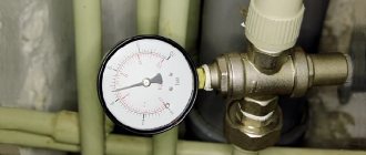
The operating pressure in the pipeline is the higher excess pressure at which the specified mode of the technological process is ensured. The minimum and maximum pressure values, as well as the physical and chemical properties of the working medium, are the determining parameters when calculating the distance between the pumps pumping the media and the production capacity.
Calculation of losses due to pressure drop in the pipeline is carried out according to the equation:
DensityThe properties of polyethylene are largely determined by its density. Russian and international standards accept the following classification of polyethylene by density groups, g/cm3:
Externally, HDPE and LDPE pipes are no different, so in the absence of markings or a passport for pipes, it is quite difficult to distinguish them. If there are two sections of HDPE and HDPE pipes of the same outer diameter with the same wall thickness, then the HDPE pipes are flattened to a lesser extent when equal loads are applied. HDPE pipes are harder than LDPE pipes, therefore, when running a fingernail over it, a barely noticeable scratch usually remains on the surface of a HDPE pipe, whereas on the surface of a LDPE pipe it is more noticeable. When hitting a hard surface, LDPE parts produce a dull sound, while HDPE parts produce a ringing or slightly ringing sound. Climate agingPolyethylene is sensitive to ultraviolet rays and heat. Under their influence, its color and mechanical characteristics change, i.e. it becomes harder and more brittle. These changes do not occur immediately and become noticeable only after a year of storing the pipes in the open air, in the sun and in unfavorable climatic conditions. Influence of temperature influencesWhen exposed to temperature, polyethylene becomes more “elastic”, i.e. more easily susceptible to deformation under mechanical forces. Typically, polyethylene pipes are calculated based on the strength of the material at a temperature of 200C. If the temperature is below this value, the strength of the material increases.
Tensile strengthThe yield strength value is quite important because... Elongation resistanceElongation can range from 800 to 1000% at a speed of 50 to 100 mm/min at a temperature of 200C. The amount of elongation is not constant and depends on the stretching speed and temperature. Longitudinal expansionThe expansion coefficient of polyethylene is 10 times higher than the corresponding coefficient of steel. The expansion coefficient of polyethylene is 0.15 - 0.20, while that of steel is 0.011 mm/m0C. This should be taken into account when laying pipelines from polyethylene pipes and precautions should be taken. RelaxationIf polyethylene is subjected to constant deformation, then with increasing duration of exposure the stress of the material decreases, because he adapts to the new state. Thermal insulation propertiesPolyethylene has good thermal insulation properties. However, for underground pipelines, the thermal insulation properties of the soil are often more significant than the thermal insulation properties of the pipe itself. The thermal conductivity coefficient of polyethylene is 0.36-0.43 W/m0K. Chemical resistancePolyethylene pipes have high chemical resistance. FlammabilityWhen in contact with fire, polyethylene quickly ignites, melts and drips down.
|

