When installing household pipelines, no calculations are made, since for these purposes they use standard pipes, the strength of which is sufficient to withstand the pressure of water, gas, etc. But building industrial lines without a specific calculation is usually scary, since this can lead to rapid failure system and other unpleasant consequences.
In this article we will look at the basics of how to calculate the strength of a pipe, and some other parameters that you need to know before building a structure.
Strength calculation
It must be stated that calculating the strength of the pipe is needed not only to ensure that the pipeline is reliable. This will also allow you to avoid cost overruns, since excessive strength will lead to higher construction costs. Based on this, design is no less a serious stage of pipeline construction than its installation.
So, this calculation involves determining several main parameters:
- The internal diameter of the pipe depending on the flow rate of the transported liquid,
- Inner diameter depending on hydraulic resistance,
- Wall thickness.
Any parameter is determined using certain formulas, which we will review below.
Calculation of internal diameter
It is possible to find out the optimal internal diameter of a pipe at a given speed of fluid flow in its flow rate and pipeline with your own hands using the formula - D = 4Q3600v?y m, where:
- Q - fluid flow rate, measured in mg/h.
- v is the speed of fluid flow in the pipeline, measured in m/sec.
- y is the specific gravity of the liquid at given parameters, measured in kg/m3. This value is taken from reference books.
The speed of movement of various liquids and gases is determined by calculations and substantiated by practical experiments. Based on this, when making calculations it is possible to use the following data:
| For water and all kinds of low-viscosity liquids (such as acetone, alcohol, mild solutions of acids and alkalis, gasoline, etc.) | 15 - 30 m/sec |
| For high pressure gases and superheated steam | 30-60 m/sec |
| For saturated steam and compressed air | 20 - 40 m/sec |
From the above formula it follows that the cross-sectional diameter of the pipeline depends on the flow rate of the liquid. The higher it is, the smaller the flow area should be, and accordingly, the lower will be the costs of constructing the structure.
Hydraulic resistance
When moving liquid or gas through a pipeline, resistance necessarily appears due to friction of the transported product against the walls of the pipe and various obstacles in the system. This resistance is called hydraulic. The higher the flow density and speed of the liquid, the greater the hydraulic resistance.
The diameter of the pipeline can be determined from the given pressure loss.
The instructions for performing this calculation are as follows – D=?L?p•y•v2g kgf/cm2, where:
- ?p = P1-P2 - specified or permissible pressure loss between the starting and ending points of the pipeline, measured in kgf/cm2.
- L is the length of the highway.
- ? — coefficient of hydraulic resistance, can be 0.02–0.04.
- g is the acceleration due to gravity, which is equal to 9.81 m/sec.
It goes without saying that this calculation makes it possible to determine the pressure loss in a straight pipe. As for the determination of this fittings and fittings indicator, it is found by the loss of pressure on a straight section of a pipe of the appropriate diameter and with an equivalent length.
An equivalent length is a straight section of pipe whose hydraulic resistance is equal to the resistance of the fitting, other conditions being equal.
Wall thickness
The main pipe parameter that affects strength is the wall thickness.
This indicator depends on several factors:
- Internal and external pressure exerted on the pipe,
- Pipeline diameter,
- The material from which the pipe is made and its corrosion resistance.
Most pipelines are subject to only internal pressure. Vacuum pipelines and systems with jackets designed for heating easily solidified or crystallizing products with steam are subject to external pressure.
The thickness of the walls of metal pipes, which are exposed to internal excess pressure, is determined by calculating strength and adding thickness, which is allocated for wear from corrosion.
To do this, use the following formula – S= Sp-C,
- Sp is the design thickness, measured in mm.
- C—corrosion allowance. In most cases, it forms 2-5 mm (for moderately aggressive environments).
The calculated wall thickness can be taken using the following formula - Sp=pDн230?add?+P mm, where:
- p—excess internal pressure in the pipe, kgf/cm2.
- Dн—outer diameter of the pipeline.
- ?add—permissible tensile strength, cgs/mm2. This indicator can be determined from reference books, depending on the temperature of the transported liquid and the grade of steel.
- ? — strength coefficient of the weld. If the pipe is seamless, then coefficient ?=1. For welded pipes, this indicator can be 0.6-0.8, depending on the type of welding and weld seam.
Note! When installing a pipeline, as well as in case of its repair, you cannot install individual random parts made of untested or little-known material, as this can lead to an accident in the system.
It must be stated that when calculating pipelines, attention is paid not only to the thickness of the pipes, but also to the material itself. For example, if the temperature at which the system will be operated is less than 450 degrees Celsius, then pipes made of grade 20 steel are used.
If the temperature of the transported product in the system is high, then choose 12Х1МФ steel. This allows the use of pipelines with narrower walls. Accordingly, the price of the structure greatly depends on the thickness of the walls.
Dependence of speed on pressure
In water supply, there is one very important relationship - the dependence of pressure on the speed of water in the pipeline. This property is described in detail in Bernoulli's physical law. We will not consider it in detail, but we will only point out its essence - as the speed of water flow increases, its pressure in the pipe decreases.
It so happens that not all plumbing fixtures are designed for operation at high pressure; in most cases they are limited to 5-6 atmospheres, otherwise there will be increased wear and premature failure.
In central highways, this figure is much higher - it can reach 15 atmospheres, and therefore, to reduce it, when connecting internal systems, pipes of smaller diameter are used.
Pipeline stability
When calculating pipelines, in addition to the strength of the pipeline, a critical parameter is its stability in the longitudinal direction.
This calculation is made from the condition - S?mNcr, where
- S is the longitudinal equivalent axial strengthening in the system section.
- m is the coefficient of system operating conditions. This value is found in reference books.
- Ncr – critical longitudinal strengthening, at which the pipeline loses longitudinal stability. This value must be determined in accordance with existing rules of structural mechanics, taking into account the initial curvature of the system, the presence of ballast that secures the pipeline, and the features of the soil. In flooded areas, it is also necessary to take into account the hydrostatic effect of water.
Note! Longitudinal stability must be controlled for curved sections in the bending plane of the highway. On straight sections, the longitudinal stability of underground sections must be controlled in the vertical plane; the radius of the initial curvature is also taken equal to 5000 m.
Longitudinal equivalent axial hardening should be determined depending on the impacts and design loads, taking into account the transverse and longitudinal movements of the highway.
The calculation is performed using the following formula −
S=100 [(0.5-?)?kts+?E?t]F
- ? — coefficient of linear expansion of the pipe material,
- E is a variable elasticity parameter,
- ?t is the calculated temperature difference,
- ?кц - hoop stresses from internal design pressure,
- F – cross-sectional area of the pipeline.
Note! When determining the stability of overhead highways, it is necessary to calculate anchor supports, arch systems, anchor hanging supports and other structural elements for overturning and the possibility of shifting.
What it is?
In order for the water supply system to function properly, water supply services constantly maintain a certain pressure in it.
Pressure is measured by a physical quantity equal to the force of water acting on the walls of the pipeline.
With its help, the water supply is achieved in such a state in which it will fully function without the risk of emergency situations:
- burst pipes,
- shut-off valves
- various plumbing equipment.
Strength classes of metal pipes
To make it easier to select suitable pipes after completing all the necessary pipeline strength calculations, pipe strength classes were introduced. In this case, the strength of the products is assessed by the tensile strength of the metal.
Several pipe strengths are indicated by the letter “K” and a standard value in kgf/mm2 from 34 to 65. For example, gas pipelines in the middle zone, taking into account the average air temperature of about 0 degrees Celsius and the operating pressure in the system of 5.4 MPa , made from pipes of strength class K52.
In the conditions of the Far North, where the average temperature is -20 degrees Celsius and the operating pressure in the system is planned to be 7.4 MPa, gas pipelines are made from pipes of strength class K55-K60.
Conclusion
We looked at the basics of how pipelines are calculated for strength and stability. Of course, when installing industrial highways, a much more complex design is performed, which involves a number of other actions, so this work is performed exclusively by professionals. However, when installing a household system, you can find out all the necessary values yourself.
You can get more information on this topic from the video in this article.
Did you like the article? Subscribe to our Yandex.Zen channel
Calculation of pipe mass
As a rule, when calculating a system, a value for the mass of pipes may be required, for example, in order to correlate it with the load-bearing properties of supports or transportation costs.
Indeed, for this there is no need to calculate mathematically how much a specific section of a particular pipe weighs, since the reference information contains the correct weight of a linear meter of the most different types of pipes.
You just need to know the following information:
- Pipe material,
- External diameter,
- Wall thickness, etc.
Once the weight of one linear meter is known, this value must be multiplied by the number of linear meters.
How to find out power: step-by-step instructions
The most accurate way to determine the pressure of a water supply system can be a built-in pressure gauge - it is installed at the entrance to the internal network immediately after the shut-off valves with a filter.
If such equipment is not installed, then you can make a portable analogue yourself.
For this you will need:
- pressure gauge up to 6 atmospheres;
- threaded extension;
- adapter (if necessary);
- fumlenta;
- adjustable wrench.
Work order:
- A threaded extension is attached to the pressure gauge, onto which an adapter is attached (if necessary). To ensure the accuracy of measurements, the joints are sealed using fume tape.
- Disconnect the watering can from the shower hose and screw on the previously prepared pressure gauge; the connection is sealed with fume tape.
- Fully open the shower valve and take readings from the pressure gauge.
This method is the most accurate, however, if you urgently need to know the pressure, but there is no pressure gauge at hand, then you can use another, albeit less accurate, method: determining the pressure by water flow.
Measurement procedure:
- A 3-liter container is placed under the tap, which is previously opened to full capacity.
- At the same time, time is recorded on a stopwatch and how long it will take to fill the container.
- The obtained time is checked against the tabular data and the pressure is set.
Table: dependence of pressure on water flow:
The video clearly shows how you can measure water pressure yourself:
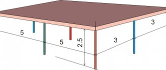
External surface area
When installing various pipelines, they may require insulation, waterproofing, painting, etc. To do this, you need to find out the area of the pipeline, which will allow you to calculate the amount of material. In order to perform this calculation, you need to multiply the circumference of the outer section by the length of the pipe.
The formula for determining a circle is as follows - L=?D. We denote the length of the pipe section as H.
Under such conditions, the area of the outer circumference of the pipe will look like this - St=?DH m2, where:
- St is the surface area of the pipe, which is measured in square meters.
- ? — The number “pi”, which is constantly equal to 3.14,
- D - outer diameter,
- H - as mentioned above, denotes the length of the pipe in meters.
For example, there is a pipe 5 meters long and 30 cm in diameter. Its surface area is St=?DH=3.14*0.3*5=4.71 square meters.
Based on the above formulas, it is also possible to perform the volume area and calculation of the pipeline of its internal walls. To do this, you only need to change the value of the external diameter in the calculations to the value of the internal one. All these parameters may be required when installing a household pipeline.
What is the power in the DHW and cold water systems?
The water pressure in multi-storey buildings connected to the central water supply network is not constant.
It depends on factors such as the number of storeys in the building or the time of year - so in the summer season, especially in multi-storey buildings, the lack of cold water becomes especially noticeable, which at this time is used for watering house or garden plots.
Municipal services in practice try to keep the level at an average of 3-4 atmospheres, although not always successfully. The minimum indicators at which the pipeline of a house can function (for both cold water supply and hot water supply) are 0.3 bar per floor.
This is explained simply - cold water is used more actively, since it is needed for the functioning of the sewage system. Therefore, the maximum indicators for cold water supply will be 6 atmospheres, and for hot water supply - 4.5 atmospheres.