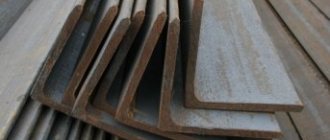
Metal structures are a complex and extremely important topic. Even a small mistake can cost hundreds of thousands and millions of rubles. In some cases, the cost of an error may be the lives of people at a construction site, as well as during operation. So, checking and double-checking calculations is necessary and important.
Using Excel to solve calculation problems is, on the one hand, not new, but at the same time not entirely familiar. However, Excel calculations have a number of undeniable advantages:
- Openness - each such calculation can be disassembled piece by piece.
- Availability - the files themselves exist in the public domain, written by MK developers to suit their needs.
- Convenience - almost any PC user is able to work with programs from the MS Office package, while specialized design solutions are expensive and, in addition, require serious effort to master.
They should not be considered a panacea. Such calculations make it possible to solve narrow and relatively simple design problems. But they do not take into account the work of the structure as a whole. In a number of simple cases they can save a lot of time:
- Calculation of beams for bending
- Calculation of beams for bending online
- Check the calculation of the strength and stability of the column.
- Check the selection of the rod cross-section.
Universal calculation file MK (EXCEL)
Table for selecting sections of metal structures, according to 5 different points SP 16.13330.2011 Actually, using this program, you can perform the following calculations:
- calculation of a single-span hinged beam.
- calculation of centrally compressed elements (columns).
- calculation of tensile elements.
- calculation of eccentrically compressed or compressed-bending elements.
The Excel version must be at least 2010. To see instructions, click on the plus sign in the upper left corner of the screen.
Coefficients φ of longitudinal bending of centrally compressed steel elements
| Element flexibility | Values of φ at Ry, MPa | |||||
| 200 | 240 | 280 | 320 | 360 | 400 | |
| 10 | 0,988 | 0,987 | 0,985 | 0,984 | 0,983 | 0,982 |
| 20 | 0,967 | 0,962 | 0,959 | 0,955 | 0,952 | 0,949 |
| 30 | 0,939 | 0,931 | 0,924 | 0,917 | 0,911 | 0,905 |
| 40 | 0.906 | 0,894 | 0,883 | 0,873 | 0,863 | 0,854 |
| 50 | 0,869 | 0,852 | 0,836 | 0,822 | 0,809 | 0,796 |
| 60 | 0,827 | 0,805 | 0,785 | 0,766 | 0,749 | 0,721 |
| 70 | 0,782 | 0,754 | 0,724 | 0,687 | 0,654 | 0,623 |
| 80 | 0,734 | 0,686 | 0,641 | 0,602 | 0,566 | 0,532 |
| 90 | 0,665 | 0,612 | 0,565 | 0,522 | 0,483 | 0,447 |
| 100 | 0,599 | 0,542 | 0,493 | 0,448 | 0,408 | 0,369 |
| 110 | 0,537 | 0,478 | 0,427 | 0,381 | 0,338 | 0,306 |
| 120 | 0,479 | 0,419 | 0,366 | 0,321 | 0,287 | 0,260 |
| 130 | 0,425 | 0,364 | 0,313 | 0,276 | 0,247 | 0,223 |
| 140 | 0,376 | 0,315 | 0,272 | 0,240 | 0,215 | 0,195 |
| 150 | 0,328 | 0,276 | 0,239 | 0,211 | 0,189 | 0,171 |
| 160 | 0,290 | 0,244 | 0,212 | 0,187 | 0,167 | 0,152 |
| 170 | 0,259 | 0,218 | 0,189 | 0,167 | 0,150 | 0,136 |
| 180 | 0,233 | 0,196 | 0,170 | 0,150 | 0,135 | 0,123 |
| 190 | 0,210 | 0,177 | 0,154 | 0,136 | 0,122 | 0,111 |
| 200 | 0,191 | 0,161 | 0,140 | 0,124 | 0,111 | 0,101 |
| 210 | 0,174 | 0,147 | 0,128 | 0,113 | 0,102 | 0,093 |
| 220 | 0,160 | 0,135 | 0,118 | 0,104 | 0,094 | 0,086 |
Online calculators
Russia and CIS countries
The only site of its kind for a practicing engineer, providing calculators for construction design with calculations according to SP, SNiP, there are calculators for calculating reinforced concrete, steel structures, calculators for calculating foundations.
The purpose of the calculon is to automate the preparation of a commercial proposal for design work, according to reference price reference books approved by the government of Moscow and Russia. The calculon is useful for managers and estimators of design organizations; it allows you to quickly determine the approximate cost of any design work that is covered by reference price reference books.
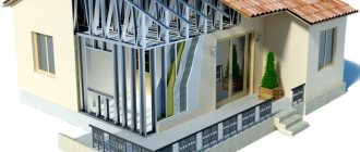
Interestingly designed calculators will help you when building your frame house, solving the need to count the amount of building materials or calculate the dimensions of a particular structural detail.
Convenient free online matrix calculator. The site implements all the basic operations of a matrix calculator on matrices, as well as methods that use matrices to solve systems of linear equations.
Convert easily and simply!
Foreign
The site has more than several hundred calculators for solving complex equations and formulas in the fields of electricity, mechanics, chemistry, electronics, civil engineering, metallurgy, oil and gas, optics, physics, mathematics, etc.
Are you a mechanical engineer, design engineer, drafting engineer, technical worker or student? Need to work with professional computing systems? But you are not ready or cannot pay thousands of rubles for inadequately complex or incomprehensible solutions? Then you just need MITCalc
Good online calculators for construction topics, static calculations of beams, etc.
Calculation of wooden structures. These interactive tools are available free of charge to help engineers and architects design buildings using wood as a structural material.
Bendingmomentdiagram is a free online calculator that generates shear force and bending moment diagrams for most simple beams. The calculator is fully customizable to suit most beam designs, which is not available in most other calculators.
A beautifully designed version of calculators for calculating steel beams, timber beams and base plates with anchor bolts.
Quick solutions to technical problems. Select a calculator below to get started!
An excellent selection of calculators for calculating building structures made of various materials.
Xcalcs is a set of tools for engineering calculations in the field of structural analysis, for direct use in a web environment. You'll find it listed under the "library" heading in the table of contents. Check this list often, calculation sheets and tools are updated regularly!
Tools and basic information for design, engineering and construction.
The site of practicing engineers contains calculators for calculating wind loads, seismicity, foundations, frames, and separately, beams and columns.
A large selection of calculators with a varied selection of topics for calculating building structures, very high-quality calculators made by practicing engineers.
Great selection of construction calculators!
Here you will find an excellent selection of calculators for calculating mathematics, finance, construction, statistics, physics, unit conversion calculators.
Examples of calculation of rafters and sheathing
Attention: some changes have been made to the text of the article in order to simplify the calculation procedure
Given:
The plan is for a two-story house of 8x10 m, a floor height of 3 m (including interfloor ceilings). Place of construction - Moscow region. A house with five load-bearing walls: 4 external and one internal, the thickness of the external walls is 0.51 m, the thickness of the internal wall is 0.38 m. The roof is corrugated asbestos-cement sheets. The rafter system is a gable roof with support posts along the central load-bearing wall, the pitch of the rafters is 1 m, the sheathing is unedged boards 25 mm thick. The attic space is non-residential.
Note: For greater reliability, it is better to make a continuous flooring and additional waterproofing with roofing felt before laying the slate, but we will limit ourselves to calculating the budget option.
Online calculator for calculating a rack (column) made of rolled steel
Specify the type of rental
Circle Square Strip Hexagon Rolled material Type and purpose of racks
If your material is not in the table, but you know the calculated resistance of this material, enter its value in this field (kg/cm2):
Enter parameters for calculation
| Rack (column) length L, m | Size D or Dv or A, mm |
| Dimension B, mm | Load on rack P, kg |
Online logic for calculating the strength and stability of a rolled steel rack
According to the Updated edition of SNiP II-23-81 (SP16.13330, 2011), when calculating the strength of steel elements under central tension or compression by force P, one should use the formula:
P / Fp * Ry * Yc <= 1
- where P is the effective load.
- Fp is the cross-sectional area of the column.
- Ry is the calculated resistance of the material (column steel), selected according to table B5 of Appendix “B” of the same SNiP.
- Yc – coefficient of working conditions according to Table 1 of SNiP (0.9-1.1). In accordance with the note to this table (point 5), the calculator assumes Yc=1.
Checking the stability of solid cross-section elements under central compression by force P should be performed according to the formula:
P/Fi * Fp * Ry * Yc <= 1
where Fi is the longitudinal bending coefficient of centrally compressed elements.
The Fi coefficient was introduced to compensate for the possibility of some non-straightness of the column, insufficient rigidity of its fastening and inaccuracy in the application of load relative to the axis of the column.
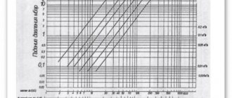
The value of Fi depends on the grade of steel and the flexibility of the column and is often taken from table 72 of SNiP II-23-81 of 1990, based on the flexibility of the column and the calculated resistance of the selected steel to compression, tension and bending.
This somewhat simplifies and roughens the calculations, since SNiP II-23-81* provides special formulas for determining Fi. Flexibility (Lambda) is a certain quantity that characterizes the properties of the rod in question depending on its length and transverse parameters. sections, in particular the radius of gyration:
Lambda = Lr/i
- here Lr is the design length of the rod,
- i – radius of inertia of the cross section of the rod (column).
The radius of inertia of section i is equal to the square root of the expression I / Fp, where I is the moment of inertia, Fp is its area.
Lr (pitch length) is defined as Mu*L; here L is the length of the stand, and Mu is the coefficient, depending on the scheme of its fastening:
- “terminal-console” (free end) – Mu=2;
- “seal-seal” – Mu = 0.5;
- seal – hinge” – Mu = 0.7;
- “hinge – hinge” – Mu = 1.
It should be borne in mind that if the form has a transverse. sections of two radii of inertia (for example, a rectangle), the smaller one is used when calculating Lambda.
To use them, you need to make a selection in the table of the online calculator “Type, purpose of racks”. The maximum flexibility of the struts, in addition to their geometric parameters, also depends on the longitudinal bending coefficient (Fi), the effective load (P), the design resistance of the strut material (Ry) and its operating conditions (Yc).
The maximum flexibility, stability and strength of the racks, in addition to their geometric parameters, also depends on the longitudinal bending coefficient (Fi), the effective load (P), the design resistance of the rack material (Ry) and its operating conditions (Yc).
Online calculator for calculating stands for strength, stability and flexibility
The online calculator below is designed to calculate a centrally loaded rack (column) made of rolled steel of round, square, rectangular and hexagonal sections for strength, stability and bending.
If you need to calculate online the strength, bending and stability of a STEEL PIPE rack, look HERE. Or the calculation of a rack made of CHANNEL, I-beam, T-beam and ANGLE for strength, stability and flexibility. When designing building structures, it is necessary to adopt schemes that ensure the strength, stability and spatial immutability of the structure as a whole, as well as its individual elements during installation and operation.
Therefore, the rack, which is under the action of a compressive load, must be checked:
- For strength;
- Sustainability;
- Acceptable flexibility.
To calculate, we suggest you use an online calculator specially designed for our website!
Reducing a concentrated load to an equivalent uniformly distributed one
When calculating some building structures, for example, floor beams, lintels for load-bearing walls, rafter legs, etc. sometimes it is necessary to take into account that part of the loads acting on such structures is uniformly distributed, while the other part is conditionally concentrated loads.
This in turn means that the calculation must be carried out using different formulas, for example, determining the maximum value of the bending moment separately for a uniformly distributed load and separately for concentrated loads. The same applies to determining the maximum deflection of the structure. It’s good if there is only one such concentrated load, the calculations will not become much more complicated, but if there are several such concentrated loads, and they are applied at different distances from each other and asymmetrically, then the calculation becomes quite complicated. Meanwhile, the more concentrated loads act on a building structure, the closer the total diagram of moments from these concentrated loads is to the diagram from a uniformly distributed load. Therefore, to simplify the calculations of structures with a constant cross-section along the length, it is quite acceptable to replace concentrated loads with an equivalent uniformly distributed one
However, this must be done carefully, since the options for applying concentrated loads are different:
Example of calculation of a metal centrally compressed column:
There is: a desire to make a canopy near a brick house approximately like this:
Figure 1. Design diagram of a canopy measuring 10 by 6 meters with columns 2.5 meters high.
In this case, the only centrally compressed column under any fastening conditions and under a uniformly distributed load will be the column shown in red in Figure 1. In addition, the load on this column will be maximum. Columns marked in blue and green in the figure can be considered as centrally compressed, only with an appropriate design solution and a uniformly distributed load, columns marked in orange will be either centrally compressed or eccentrically compressed or frame racks calculated separately. In this example, we will calculate the cross section of the column indicated in red. For calculations, we will assume a permanent load from the canopy’s own weight of 100 kg/m2 and a temporary load of 100 kg/m2 from the snow cover.
2.1. Thus, the concentrated load on the column, indicated in red, will be:
N = (100+100) 5 3 = 3000 kg
2.2. We preliminarily accept the value λ = 100, then according to Table 2 the bending coefficient is φ = 0.599 (for steel with a design strength of 200 MPa, this value is taken to provide an additional safety margin), then the required cross-sectional area of the column is:
F = 3000/(0.599 2050) = 2.44 cm2
2.3. According to Table 1, we take the value μ = 1 (since the roof covering made of profiled decking, properly fixed, will provide rigidity of the structure in a plane parallel to the plane of the wall, and in a perpendicular plane, the relative immobility of the top point of the column will be ensured by fastening the rafters to the brick wall), then the radius of inertia
i = 1 250/100 = 2.5 cm
2.4. According to the assortment for square profile pipes, these requirements are satisfied by a profile with cross-sectional dimensions of 70x70 mm with a wall thickness of 2 mm, having a radius of gyration of 2.76 cm. The cross-sectional area of such a profile is 5.34 cm2. This is much more than is required by calculation.
2.5.1. We can increase the flexibility of the column, while the required radius of gyration decreases. For example, at λ = 130 the bending coefficient is φ = 0.425, then the required cross-sectional area of the column is:
F = 3000/(0.425 2050) = 3.44 cm2
2.5.2. Then
i = 1 250/130 = 1.92 cm
2.5.3. According to the assortment for square profile pipes, these requirements are satisfied by a profile with cross-sectional dimensions of 50x50 mm with a wall thickness of 2 mm, having a radius of gyration of 1.95 cm. The cross-sectional area of such a profile is 3.74 cm2, the moment of resistance for this profile is 5.66 cm3.
2.6. Let's check whether the accepted profile is acceptable in terms of maximum flexibility. The exact flexibility value will be
λ = 250/1.95 = 128.2
the value of coefficient a will be
a = 3000/(0.425 2050 3.74 1.1) = 0.837
then the maximum permissible value of flexibility is
λmax = 180 - 60 0.837 = 129.8 > 128.2
We have met the requirements for maximum permissible flexibility.
Instead of square profile pipes, you can use an equal angle angle, a channel, an I-beam, or a regular pipe. If the calculated resistance of the steel of the selected profile is more than 220 MPa, then the cross section of the column can be recalculated. That’s basically all that concerns the calculation of metal centrally compressed columns, I’ll only add that if you are not doing the calculations professionally and you can’t only take into account all possible loads, but can’t even imagine them, then don’t use the value λ > 80. The less flexibility , the more reliable the design. If you noticed, Table 2 does not provide for flexibility values exceeding 220, although theoretically the flexibility can be 300 or 1000; simply considering rods with such flexibility as load-bearing ones does not make any sense - they are very unstable.
If you follow the above recommendation, then even a pipe with a cross-section of 70x70x2 mm will not be enough, and you will need a pipe with a cross-section of 80x80x3 mm, for which the radius of gyration is i = 3.12 cm and, accordingly, the flexibility will be λ = 250/3.12 = 80.1. For example, you are calculating exactly the same canopy, but not connected to a relatively rigid brick wall, but free-standing. In this case, the value of the coefficient will most likely be μ = 2, but you, without delving into the complexity of the relationships between building structures, decided that μ = 1 would be enough. In this case, the accepted limitation on flexibility will protect your structure from destruction, because with μ = 2, the value of the design length of the column will be lef = 2·250 = 500 cm, and the flexibility of the column λ = 500/3.12 = 160.25 i.e. at the limit of the maximum permissible (and even beyond the limit). If you did not make a mistake in choosing the design scheme, but still used the recommended flexibility limit λ ≤ 80, then as a result you will receive an increased safety margin and a slight increase in the cost of the structure. It’s up to you to decide which is better: to make a structure with an increased safety margin or to completely redo it after a collapse.
And yet, the application of a load exactly at the center of gravity of the column and the absolute verticality of the column are possible only in theory; in practice, there is always some eccentricity in the application of the load, and if for columns with a cross section of 40x40 cm, a change in the point of application of the load by several millimeters or even a whole centimeter can not be taken into account, having set the appropriate safety factor, then for a column with a cross section of 5x5 cm such a deviation can be critical. Why? Let's figure it out now.
Basics of strength of strength
By and large, the basics of the theory of strength of materials (strength of materials) are even simpler than the multiplication table. The multiplication table is large, it needs to be stupidly memorized as “Our Father,” and the basics of strength of strength are reduced to several basic provisions, which are quite easy to visually demonstrate and therefore easy to remember.
However, this is my subjective opinion. Many people believe that the strength of proof is very difficult, there is even a saying: “if you pass the strength of proof, you can get married.” It is easier for humanists and doctors to study a dozen weighty volumes before a session, and for people with an analytical mindset it is easier to remember several basic principles of a particular discipline and it is not even necessary to remember all the formulas. Most of the formulas can be derived by yourself, using the mathematical apparatus and relying on the basic principles, at least that’s what I did during the exams.
Circumstances were such that I missed the introductory course of lectures on strength strength materials, since I returned to the institute after serving in the navy 2 weeks before the session, so I had to learn the basics of strength strength materials myself, for which the most severe and incorruptible teacher on the stream, who failed more than one hundred students , gave me a five. Well, off we go, the teachers, seeing an “A” on the strength of materials test, did not dare to give a lower grade in their subject, and in the end I received a diploma with honors. However, let's not get distracted, but let's get back to the basics.
Preliminary Considerations
The calculator provides for the calculation of beams from certain types of rolled products for bending and deflection for various schemes of their fastening and loading. The load of beams can be distributed (“q” in diagrams 3, 4, 5, 9, 15 and others) or concentrated (“P” in diagrams 1, 2, 6, 7, 8 and others.)
Beam fastening can be:
- cantilever with rigid termination of one of the ends (for example, schemes 1, 2, 3 and others);
- “embedding - embedding”, when both ends of the beam are rigidly clamped (embedded), schemes 6, 7, 8, 9;
- “hinge - hinge” (diagrams 12, 13, 14, 15 and others), with the left hinge being fixed and the right hinge being movable;
- “sealing - hinge”, (diagrams 9, 10, 11 etc.)
Rigid embedding of the beam prevents it from turning or moving in any direction. A fixed hinge allows only rotation of the beam at the point of attachment in the vertical plane. The movable hinge allows the beam to rotate at the point of attachment in a vertical plane and move along its own axis. These movements are very insignificant and are a consequence of the deformation of the beam under load.
The main type of this deformation is its deflection, the magnitude of which, along with the load applied to the beam, also depends on its length, the dimensions of its cross section and the physical characteristics of the material, in this case, on its modulus of elasticity (“E”).
From the dimensional characteristics of the cross section of the beam, the moment of inertia of the section (“I”) is used to calculate the deflection; the amount of deflection also depends on the position of the beam point being checked relative to the supports. The permissible amount of deflection of beams is determined by their purpose and place in building structures and is regulated by the relevant SNiP; in mild cases it should not exceed 1/120 - 1/250 of the length of the beam.
Therefore, we strongly recommend that you check the calculation results for acceptability after using the calculator.
Using our online calculator you can calculate:
- Allowable bending stress (kg/cm2).
- Maximum bending moment (kg/cm).
- Bending resistance moment (cm3).
- Axial moment of inertia of the cross section (cm4).
- Maximum deflection (cm).
- Design bending stress (kg/cm2).
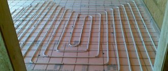
It is impossible to build a house without the use of dividing floors. One of them separates the house from the outside space from below, the second from above. The floor and ceiling of the building are mounted on them, and insulation is performed. Horizontal lintels must support their own weight, as well as transfer loads from furniture, equipment and people in the building.
Where are metal columns used?
Most construction work begins with the installation of supports. After this, other parts of the metal structures are attached to them: longitudinal and transverse beams, half-timber posts, trusses, floors, etc.
Load-bearing metal columns are building supports that are designed to maintain the integrity of the building and delimit the internal space of the facility. Not only the appearance of the structure, but also the safety of its operation will depend on the quality of the columns and the correctness of their installation.
Metal columns are often used in the construction of:
- factory and warehouse premises;
- shopping and entertainment facilities;
- household objects;
- structures for storage, maintenance and repair of large equipment;
- additional administrative and utility premises.
The purpose of steel supports is as follows:
- take loads from floors, walls and overhead cranes;
- support the roof, enclosing structures and upper elements of the supporting frame;
- evenly distribute the total mass of the external and internal parts of the structure, various equipment and building visitors onto the foundation;
- withstand aggressive weather conditions;
- act as a decorative element of the interior or exterior of a building.
Each column simultaneously performs several tasks: it ensures the stability of the overall structure, divides the space into parts and connects various frame elements. Technical equipment is also attached to metal columns in industrial buildings. Steel supports are strong, reliable and can be used for a long time.
Example of triangular truss calculation
When calculating industrial trusses spanning large spans and operating under heavy loads, up to 10-15 types of sections, or more precisely profiles with different section parameters, can be used. This is due to the fact that the stresses in the truss rods are different and therefore the most accurate selection of the cross-section for industrial volumes of truss production provides significant savings. In private construction, when making trusses, 1-2, maximum 3 types of sections are used, not only for economic, but also for aesthetic reasons, and therefore it is enough to calculate the maximum loaded rods and, based on these indicators, take the cross-section for the remaining rods of the truss. In general it might look something like this:
Calculation of a wooden stand in compression. General provisions.
Wooden posts and columns, despite the abundance of rolled metal, reinforced concrete and plastic, are still in demand. It's nice to have a wooden gazebo in the garden or a canopy in the yard. As a rule, the cross-section of the elements of such gazebos or canopies is selected for aesthetic (architectural) reasons, but it does not hurt to calculate the load-bearing elements of such structures and, in particular, columns or racks for strength, since the historically established architectural canons are approximately the same throughout the country, but the load on the structures can be noticeably different. The same applies to support posts, as well as struts for rafter systems, and any other wooden trusses.
All basic requirements for the calculation of wooden columns, racks, struts and any other elements operating in central or eccentric compression can be found in SNiP II-25-80 (1988). And this article only outlines in the most simplified way the basic principles of calculating compressible wooden elements, nothing more.
Things to consider
All developers try to be both economical and efficient at the same time.
Given its low cost and decent service life, installing a fence made of corrugated sheets fits within such a framework. At the same time, you and I have observed more than once in neighboring areas when in the spring the ground thaws, the birds sing, but the pillars are littered, the sheets are bent, and the gate has sagged. What is the reason? It seems that the culprit here is the principle “as long as it is” or “it’s still better than it was.” Such negligence will certainly result in additional costs of time and money. Therefore, we first evaluate the operating conditions, and only then design the structure:
- Investigate the nature of the soil: degree of heaving, thickness of the chernozem layer, presence of clay, level of sand and groundwater. This is important for choosing the right method for installing pillars: concreting, butting with crushed stone and sand, or strip foundation.
- Consider the location of the site and possible wind loads. Factors directly influence the choice of the profile size of a metal post, and ultimately the cost of the entire corrugated fence. For example, in some conditions you can get by with a pipe with a cross-section of 60x60x3 mm, but in another case strong gusts of wind can easily put down such supports.
Moment of inertia
The geometric characteristic, which is called the moment of inertia, is important when calculating the deflection of a beam. The formula allows you to calculate this value; we will give it a little below.
When calculating the moment of inertia, you need to pay attention to the fact that the size of this characteristic depends on the orientation of the element in space. In this case, there is an inversely proportional relationship between the moment of inertia and the amount of deflection
The smaller the moment of inertia value, the greater the deflection value and vice versa. This dependence is quite easy to track in practice. Every person knows that a board laid on its edge bends much less than a similar board in a normal position.
The moment of inertia for a beam with a rectangular cross-section is calculated using the formula:
J=b*h^3/12, where:
b – section width;
h is the height of the beam section.
Calculation of the maximum deflection value
When a beam is calculated, the formula displays all the necessary elements. It should be borne in mind that the formula used for calculations may have a slightly different form if the calculation is carried out for different types of loads that will affect the beam.
First, we present to your attention the formula used to calculate the maximum deflection of a wooden beam with a distributed load.
f=-5*q*l^4/384*E*J.
Please note that in this formula E is a constant value, which is called the elastic modulus of the material. For wood, this value is 100,000 kgf/m²
Continuing the calculations with our data used for the example, we find that for a wooden beam with a cross-section of 0.15x0.2 m and a length of 4 m, the maximum deflection under the influence of a distributed load is 0.83 cm.
Please note that when the deflection is calculated taking into account a scheme with a concentrated load, the formula takes the following form:
f=-F*l^3/48*E*J, where:
F – pressure force on the beam.
We also draw attention to the fact that the value of the elastic modulus used in the calculations may vary for different types of wood. Not only the type of wood has an impact, but also the type of timber
Therefore, a solid wooden beam, laminated veneer lumber or rounded log will have different elastic moduli, and therefore different maximum deflection values.
You can pursue different goals when calculating beams for deflection. If you want to know the limits of deformation of structural elements, then after completing the calculation of the deflection arrow, you can stop. If your goal is to establish the level of compliance of the found indicators with building codes, then they need to be compared with the data that is posted in special regulatory documents.
Methods for connecting metal columns
Metal beam joints are connections between several steel frames. Connecting parts are manufactured mainly industrially and have standard parameters. Thanks to the butt elements, the length of the metal support can increase several times.
Fastening units for metal columns allow you to connect components that are separate from each other, resulting in a common structure whose dimensions will meet all the requirements.
- Knots made to connect all metal beams.
Consist of several parts. They vary depending on their design features and are widely used in the construction of various buildings. Such units can be manufactured both industrially and as part of the construction of a specific construction project.
- Interfaces with special columns made of steel material.
The beam structure can be connected to metal supports using a hinged or rigid fastening. However, most experts recommend supporting the beams on top and applying the entire load only in the central part of the column profile frame.
- Side fastening.
When fastening from the side, in addition to the compressive load in the entire frame, a moment arises at which, due to the action of this force, an additional load line appears, deviating from the central axis (i.e., the load on the metal frame increases).
To properly distribute the load on the frame, each of its ribs should protrude from its level by an average of 1.5-2 cm. Subsequently, these same ribs will have to be shortened slightly so that the total load can be transferred to the entire area of the structure.
- The process of supporting beams from the top of metal columns.
Just as in the method described above, the beams should be supported through the rib and brought to the head of the columns. After this, they must be connected and secured with bolts.
You will need to install appropriate plates between the beams so that you don’t have to tighten them together in the future. It is worth noting that you can support two beams at once on one column head.
The key element of the connecting scheme under consideration is the beam located on the bottom flange at the very top of each column. Please note that it will have to be reinforced with a rib.
The rib should be secured so that it is above the column flange itself.
The next step is to fasten the beams together using bolts and plates (remember to ensure that the load is evenly distributed).
To avoid the formation of unnecessary nodes for supporting metal columns, you should not connect all the beams from the top. In this case, ribs on the columns are not required. It is recommended to leave a small distance between them (1-2 cm).
- Hinged column mounts on the side.
For any side mounting, it is necessary to determine the degree of deviation of the load line from the central axis. The use of a hinged fastener will result in the load being transferred only through the support rib and only to the support table.
For the manufacture of support tables, durable steel sheets are usually used. The tables are connected by welding on three main sides. The total width of the support table should be 2–4 cm greater than the size of the beam rib.
The holes are made in such a way that their diameter is 0.3-0.4 cm larger than the diameter of the bolts used for connecting.
When using hinged fasteners, ribs in the frame column are not required. A metal gasket with a thickness of no more than 0.5 cm is installed between the supporting rib and the column.
- Pairing with metal columns in a rigid version.
You can make a connecting element not only using bolts, but also using a welding machine.
It is worth noting that the use of bolts is considered the most optimal option, since in this case almost all parts are developed and produced in production. That is, when assembling the frame, you only need to install the parts and tighten the bolts more tightly.
Several thin steel sheets will need to be laid between the support beams and the column so that all the elements fit snugly together. Even minor gaps are unacceptable.
Step-by-step calculation instructions
1. Enter the type of rental: round, square, strip-shaped, hexagonal, etc.
2. Indicate the type of scheme according to which the rack is attached: in the form of a console seal, in the form of a seal seal, in the form of a hinge seal, or a hinge hinge.
3. Select the rolled material, for example: from Steel S235 - St3kp2, from Steel S245 - St3ps5 or St3sp5.
4. Establish the type of rack, its purpose, for example: transmission racks, used for support, main or secondary.
Important! If the type of material is not in the table, and its design resistance (kg / cm 2) is known, then you should enter the value in a special field. To make the calculation enter:
To make the calculation enter:
1. The length of the stand is L, expressed in meters.
2.Dimension D or Dv or A is expressed in millimeters.
3.Size B, expressed in millimeters.
4. The load on the column is P, expressed in kilograms.
According to the latest version of SNiP II - 23 - 81, when calculating the strength of steel parts equipped with central tension or compression through force P, they are calculated using the following formula:
P : Fp X Ry X Yc<=1
The stability calculation of a part having a solid cross-section with central compression by force P is calculated according to the formula:
P : Fi x Fp x Ry x Yc<=1
In the formula:
1.Fi – coefficient value indicating longitudinal bending of centrally compressed elements.
This coefficient compensates for the slight non-straightness of the rack, the lack of fastening rigidity, and the inaccuracy in determining the load along the two axes of the column.
The Fi parameter differs depending on the grade of steel material and its flexibility; as a rule, the value is determined according to table No. 72 from SNiP II-23-81 for 1990, it also depends on the resistance of the material, compression during calculation, bending and tension.
This condition makes the calculation simpler, but more crude, because SNiP specifies the engineering formulas by which Fi is calculated.
The physical quantity is the flexibility of the rack, in other words Lambda, which determines the parameters of the rack, which are the length, cross-section, including the value of the inertial radius.
LAMBDA = Lr : i
In the formula:
Lr – value of the calculated rod length.
i is the value of the inertial radius of the transverse type rod diameter.
This value, denoted i, is calculated as the square root of the value I: Fp, in which I is equal to the moment of inertia, and Fp is equal to the cross-sectional area.
Lr=Mu * L,
In the formula:
Mu is the coefficient determined by the column fastening scheme.
L – value of the rack length.
Important! If Lambda is calculated for a rectangle that has two section radii of gyration, the smaller one should be used. The flexibility of the rack, which is calculated according to the above scheme, cannot be higher than the value 220 according to table No. 19 according to SNiP II - 23 - 81, it indicates the maximum indicators of the maximum flexibility of racks of the centrally compressed type
The flexibility of the rack, which is calculated according to the above scheme, cannot be higher than the value 220 according to table No. 19 according to SNiP II - 23 - 81, it indicates the maximum indicators of the maximum flexibility of racks of the centrally compressed type.
To use them correctly, you should select a table in the calculator called Type and purpose of racks, then determine the subtype.
The value of the maximum flexibility is determined by the parameters of geometric shapes; the value is influenced by longitudinal bending, load, design resistance of the product material, and operating conditions.
Before you start using the online calculator, you should carefully study the instructions.
Calculation is not always required
If you decide to use a profile pipe to build a gate, fence, or railing, then it is not necessary to carry out bending calculations, since the load on such systems is minimal.
To accurately and quickly calculate the load on a profile pipe, you can use a calculator or the SketchUP program. (Download torrent - Official Russian version! Bit depth: 64bit, Interface language: Russian, Tablet: Present)
The calculation will be correct if the following 3 conditions are met:
- If the system has supports and an upper frame in which mechanical (not electrical!) stresses arise, then the forces will be distributed among several risers, depending on their connection to each other.
- A sufficiently large height of the system can reduce the load-bearing capacity of individual supports. This is due to the appearance of torque in the risers.
- To obtain a reliable metal structure of great height, you need to add additional supports. Thanks to the stiffening ribs that will connect the risers, mechanical stress can be distributed more evenly.
When performing direct calculations, you must have information about:
1. Types of possible loads.
They can be:
- stable, which takes into account the weight of structural parts, soil mass, roof pressure, etc.;
- long-term, which will operate over a long period, but can change at any moment: the mass of the boiler, flight of stairs, brick walls;
- short-term, operating over a short period (precipitation, mass of visitors, vehicles);
- special ones that are caused by unforeseen circumstances: rainfalls, earthquakes, volcanic eruptions, explosions, etc...
2. Dimensions of profile pipes, section shapes.
3. The total stress of the structure.
4. Strength characteristics of steel.
To calculate the load on a profile pipe use:
- tables;
- mathematical formulas;
- a special online calculator.
Using tables
When applying the first method, it is necessary to compare the physical characteristics of the pipe that will be used to construct the system with tabular data. To do this, take the values from tables 1 or 2, depending on the type of profile.
Table 1. Loads for square risers
| Section, mm | Maximum possible weight, kg | |||
| Span length, m | ||||
| 1 | 2 | 4 | 6 | |
| 40x40x2 | 709 | 173 | 35 | 5 |
| 50x50x2 | 1165 | 286 | 61 | 14 |
| 60x60x3 | 2393 | 589 | 129 | 35 |
| 80x80x3 | 4492 | 1110 | 252 | 82 |
| 100x100x4 | 9217 | 2283 | 529 | 185 |
| 140x140x4 | 19062 | 4736 | 1125 | 429 |
Table 2. Loads for rectangular risers
(for calculations use the long side)
| Section, mm | Maximum possible weight, kg | |||
| Span length, m | ||||
| 1 | 3 | 4 | 6 | |
| 50x25x2 | 684 | 69 | 34 | 6 |
| 60x40x3 | 1255 | 130 | 66 | 17 |
| 80x40x3 | 2672 | 281 | 146 | 43 |
| 80x60x3 | 3583 | 380 | 199 | 62 |
| 100x50x4 | 5489 | 585 | 309 | 101 |
| 120x80x3 | 7854 | 846 | 455 | 164 |
These tables contain data on maximum permissible weights. With such an impact on the profile, the pipe will not collapse, but will only bend.
But if you increase the mass by at least 0.5 kg, the system can be completely deformed, which will lead to destruction.
In this regard, in practice, a part with a rectangular or square cross-section is selected, the safety margin of which would be at least 2 times greater than the minimum.
Advantages of the tabular method
The tabular method is highly accurate. To use it, you need to have information about the types of supports, methods of fixing profiles on them, and types of loads.
In addition,
for complete load calculations it is necessary to have data on
:
- moments of inertia of a profile rectangular or square pipe, the value of which can be taken from the tables, starting from sections 15x15x1 5 and ending with 100x100x4 and above;
- span length;
- the amount of gravity on each riser;
- elastic modulus coefficients (taken from SNiP).
Calculation algorithms on an online calculator
The bending moment, which the calculator shows when calculating a beam, means the product of force on the arm and is calculated by the formula:
Mmax = q × l2/8, where:
- q—floor load;
- l is the span length.
The moment of resistance (required) demonstrates how much a material can resist compression, tension and bending. The maximum bending moment Mmax and the calculated resistance of wood R are entered into the formula. It turns out Wreq = Mmax/R, while R depends on a large number of corrections related to the type of wood, impregnation and temperature, but the calculator does not take them into account, giving only approximate calculation results beams.
Useful: We calculate the structure and structure of the walls of a frame house
The moment of resistance of a beam will be different for different section shapes - square, round, rectangular, oval, etc. The rectangular section, as the most common, has the following formula for determining the moment of resistance:
W = b × h2/6, in which b and h are the width and height of the beam, respectively.
The online calculator calculates the strength by comparing the moment of resistance with the required moment: according to standards Wreq ≤ W. The maximum deflection is calculated using the formula:
f = (5 × q × l4) / (384 × E × (b × h3 / 12)), in which the load on the floor is denoted by q, the span by l, the modulus of elasticity by E, the height of the beam h and its width b.
Fence post: strength calculation
We take as a base a standard fence with a span of 2 meters and a height of also 2 meters. For one column of such a span there is a wind load of the following magnitude:
F = 2 x 2 x 38.9 = 155.6 kgf
We determine the point of influence of the load (L) in the middle of the profiled sheet - 1 m, and the distance from the ground level to the lower edge of the sheet - 25 cm. As a result, the wind force forms a bending moment in the area where the column exits the soil, where the maximum loaded section is formed:
M = FLk M = 155.6 x 1.25 x 1.5 = 291.75 kgf•m
- k is the safety factor, in this case it is equal to 1.5.
Load on round pipes
Application
Round pipes can be found anywhere. Supports, racks, columns, containers - this is not a complete list of the uses of shells (the shell is a cylindrical metal sheet without ends).
The ring pipe profile can be found when laying water, oil, and gas pipelines both at home and on an industrial scale. They are an excellent material for fence posts, gates, and gates.
Due to the presence of a closed contour, a round pipe has a significant advantage in comparison with channels and angles with similar linear parameters.
As a result of dividing the first parameter by the second, the required strength was obtained. After comparing the obtained parameter with the permissible value taken from the table, a conclusion is made as to whether such a load can be applied to a particular riser or not.
If the number is less than allowed, then everything is fine. But there is one thing: the calculations are valid for stretching, not compression
.
Using a calculator
For the option with compression of a round post, you can carry out the necessary calculations using an online calculator.
First you need to familiarize yourself with additional concepts. These include:
- Loss of overall stability. Checking the loss is necessary to avoid huge losses of other types.
- Loss of local stability. We are talking about an earlier “finishing” of the rigidity of the riser walls under the action of a load on the shell. In other words, the pipe begins to bend inward, and the round section turns into a profile of an irregular curvilinear shape, which leads to loss of stability.
Using Excel
There is a special Excel program for comprehensive verification of the calculation of risers regarding stability and strength. The basis of this program is the data of GOST 14249 89. With its help, you can calculate the maximum load on a round pipe, as well as the general forces on the shell of a circular cross-section.
On the Internet you can often find the following questions: “What load can a round pipe 3, 4, 6 meters long withstand? How to calculate this using an online calculator? Can I do this myself?
We will try to give a detailed answer to these and other questions. The best explanation would be a practical calculation of the magnitude of the vertical load on a round pipe. For example, let’s take a vertical round riser with a diameter of 57 mm and a length of 3 meters (most often used for arranging sheds, garages, and other structures) and calculate how much load the pipe can withstand.
What data is needed
The algorithm for working with the program is as follows:
- First you need to open GOST 14249 89, from which you need to write down the first 5 initial values. To quickly find parameters, use the notes for each cell.
- Fill in cells D8, D9, D10, entering the linear parameters of the risers into them.
- Enter possible loads in cells D11 to D15.
Important! If internal excess pressure acts on the shell, then the value of external pressure is zero. Similarly: when the riser is exposed to external excess pressure, the internal pressure parameter will also be equal to zero
Important! Remember that the notes for each cell in the “Value” column contain a link to the numbers of the required formula, required table or drawing from GOST 14249 89
What happened as a result
You must not only be able to use the program, but also be able to explain the results obtained.
It is necessary to compare the ratio of the effective load to the permissible one: if you receive a number greater than one, the pipe is overloaded. Otherwise, the riser will withstand the given weight, provided that the load on the round pipe is calculated correctly.
Important! The user should see the value of the total influence of all acting forces and pressures
Calculator for calculating a column from a profile pipe
When choosing profile rental, the client must realize that accurate calculations of possible loads, depending on the linear and other parameters of the risers, are very important. Any structure created is designed for a specific weight.
- It is strictly forbidden to place connections or objects on it, the mass of which, taking into account the influence of weather factors, will be more than permissible.
- To know why you need to calculate the load on a profile pipe, let’s see where it is used.
- Risers with a profile section have found their application in various spheres of human activity.
- With their help:
- canopies are installed on balconies, verandas, near private houses;
- stairs, podiums, stages are assembled.
The list goes on, but the main thing to remember is:
In order for the structures to be safe, reliable, and serve for a long time, it is necessary to calculate the vertical load on the profile pipe. If this is not done, the system may not support the weight, which will lead to undesirable consequences.
The popularity of profile pipes is explained by their low cost, low weight, and high bending strength.
. When choosing rolled products with a rectangular or square cross-section, most customers understand the importance of calculating the load on the profile pipe. The correspondence of the linear dimensions of the profiles to the possible mechanical force on the part is taken into account.
What will happen if we do not take into account the possible impact of gravity on the structure?
You can’t even think about this, since when exposed to the maximum permissible weight,
2 options
:
- irreversible bending of the pipe, as it will lose its elasticity;
- destruction of the entire structure, which is fraught with negative consequences.
Calculation of reinforced concrete column
In private construction, reinforced concrete columns are not made very often, and if they are made, then as a rule they are centrally loaded columns of a fairly large cross-section and relatively short length, and it is not customary to spare reinforcement for the columns, and therefore such columns are made without special calculations and They usually have enough strength.
Meanwhile, it won’t hurt to have at least a general understanding of the principles of calculating reinforced concrete columns, and if the columns are eccentrically loaded, then it’s impossible to do without calculations. The calculation should be made in accordance with the requirements of SNiP 2.03.01-84 or SP 52-101-2003. The calculation examples below are nothing more than examples.
The purpose of the calculator to determine the bend
Wood is the most widely used material for creating frames for various buildings. From it, like from plasticine, you can create a design of any complexity. However, not the last place is occupied by such structural material as various metal profiles.
They are distinguished by such properties as plasticity, durability and strength. Not the last place among such materials is occupied by profile and round pipes. Try to imagine a carport made from a profile pipe coated with polycarbonate and the same structure from a corner.
It seems there can be no two opinions. And any pipe beam in the structure must be calculated. This is necessary for two reasons:
- Obtain an object with a sufficient margin of safety under the influence of its own weight, as well as wind and snow loads.
- Select the minimum profile acceptable for the building in order to minimize the cost of materials.
To achieve this goal, you need to use our online calculator and calculate the bending of a pipe beam. This is the case if the part is fixed on one side (cantilever). If both ends are fixed, you will need to calculate the pipe for deflection.
In this case, the following circumstances must be taken into account:
- Dimensions and cross-section: (profile or round). For a profile rectangular pipe, the calculation is made taking into account the direction of impact. When calculating beams made from a square pipe, this factor is the same for any direction of influence.
- Strength characteristics of the material, taking into account the wall thickness and grade of material. This is especially true when using beams made of round pipes, the calculation of which largely depends on the specified characteristics due to the variety of materials used.
Calculation of an eccentrically compressed column.
Here, of course, the question arises: how to calculate the remaining columns, since the load will most likely be applied to them not in the center of the section? The answer to this question greatly depends on the method of attaching the canopy to the columns. If the canopy beams are rigidly attached to the columns, then a rather complex statically indeterminate frame will be formed, and then the columns should be considered as part of this frame and the cross-section of the columns should be calculated additionally for the action of the transverse bending moment. We will further consider the situation when the columns shown in the figure 1, are hingedly connected to the canopy (we are no longer considering the column marked in red). For example, the head of the columns has a support platform - a metal plate with holes for bolting the canopy beams. For various reasons, the load on such columns can be transmitted with a fairly large eccentricity:
Figure 2 . The eccentricity of the application of a concentrated load to a column due to deflection of the canopy beam.
The beam shown in Figure 2, in beige color, will bend slightly under the influence of the load (why this will happen is discussed separately) and this will lead to the fact that the load on the column will not be transmitted along the center of gravity of the column section, but with an eccentricity e and when calculating the extreme columns, this eccentricity must be taken into account. A more accurate determination of eccentricities depends on the stiffness of the column and beam, but in this case we will not take into account the stiffness and, for reliability, we will accept the most unfavorable eccentricity value. There are a great many cases of eccentric loading of columns and possible cross sections of columns, described by the corresponding formulas for calculation. In our case, to check the cross-section of an eccentrically compressed column, we will use one of the simplest:
(N/φF) + (Mz/Wz) ≤ Ry (3.1)
Those. it is assumed that there is eccentric loading about only one axis.
In this case, when we have already determined the cross-section of the most loaded column, it is enough for us to check whether such a cross-section is suitable for the remaining columns for the reason that we do not have the task of building a steel plant, but we are simply calculating the columns for the canopy, which will all have the same cross-section for reasons of unification.
We already know what N , φ and R
Formula (3.1) after the simplest transformations will take the following form:
F = (N/Ry)(1/φ + ez·F/Wz) (3.2)
since the maximum possible value of the bending moment Mz = N·ez , why the value of the moment is exactly what it is and what the moment of resistance W is is explained in sufficient detail in a separate article.
The concentrated load N on the columns, indicated in blue and green in Figure 1, will be 1500 kg. We check the required cross-section under such a load and the previously determined φ = 0.425
F = (1500/2050)(1/0.425 + 2.5 3.74/5.66) = 0.7317 (2.353 + 1.652) = 2.93 cm2
In addition, formula (3.2) allows you to determine the maximum eccentricity that the already calculated column will withstand; in this case, the maximum eccentricity will be 4.17 cm.
The required cross-section of 2.93 cm2 is less than the accepted 3.74 cm2, and therefore a square profile pipe with cross-sectional dimensions of 50x50 mm and a wall thickness of 2 mm can also be used for the outer columns.
Note : In general, the bending moment from eccentricity in the most dangerous section, located approximately in the middle of the column height, will be 2 times less, and accordingly the required cross-sectional area will also be slightly smaller. But as I already said, when performing calculations by a non-specialist, an additional margin of safety will never hurt. Moreover, in this case we still accept a large cross-sectional area for structural and aesthetic reasons.
Calculation of maximum deflection for a beam with two supports
As an example, consider a diagram in which a beam is on two supports, and a concentrated force is applied to it at an arbitrary point. Before the force was applied, the beam was a straight line, but under the influence of the force it changed its appearance and, due to deformation, became curved.
Let us assume that the XY plane is the plane of symmetry of a beam on two supports. All loads act on the beam in this plane. In this case, the fact will be that the curve resulting from the action of the force will also be in this plane. This curve is called the elastic line of the beam or the deflection line of the beam. You can algebraically solve the elastic line of the beam and calculate the deflection of the beam, the formula of which will be constant for beams with two supports as follows.
Classification of metal columns
- Depending on the design features.
Supports of constant cross-section. The rods of such supporting elements have a constant cross-sectional size. The variety in question is widely used in buildings of various heights, hangars, and warehouses. The optimal height of a metal column of constant cross-section should not exceed 12 m. Installation of such columns in industrial buildings allows the installation of equipment with a total weight of up to 20 tons.
Stepped supports. The choice of the type of metal columns under consideration is usually determined by the need to install crane equipment with a lifting capacity of 20 tons. The column design consists of two parts, with the main load-bearing one supporting the roof truss, and the crane beam receiving the load from the crane beam of the lifting mechanism. The parts of the rod are connected using connections in the form of a solid sheet or a lattice of corners.
Separate supports. This design consists of two separate metal posts, which are connected using flexible horizontal elements. Most often, separate load-bearing columns are installed in industrial buildings with a load capacity of more than 100 tons and can reach 20 m in height. In addition, separate columns can be installed in multi-tier or low crane locations, as well as in the case of renovation work in factory premises.
- According to the load perception method.
Centrally compressed supports. In this case, the pressure is transmitted strictly along the central axis of the rod, which provokes central compression of the section. In this case, longitudinal loads are taken by auxiliary elements.
Eccentrically compressed supports. The action of the compressive force in them occurs along a trajectory slightly removed from the central axis, as if along a curved line. In addition, the column can also be subject to horizontal loads. In such cases, the structure usually has an asymmetrical cross-section to more evenly distribute the load and reduce the consumption of material and the mass of the metal column.
- By type of rod element.
Solid supports. Their design includes only a rod element. In most cases, solid columns are welded or rolled I-beams. With equal stability in both directions, solid columns can have a cruciform shape. It is worth noting that the cross section is considered more rigid and reliable compared to the I-beam.
Through supports. The design of through columns most often consists of two guide rods that are connected by a lattice. In order to strengthen the support, the lattice is usually placed in two planes, using single corners for its manufacture.