In this article we will solve the problem of pressure loss in a pipeline. This article will help you understand how resistance to flow occurs. Using real numbers, I will describe the algorithm on how to do this. We use basic formulas.
Let's look at a simple example with a pipe, as you can see in the image at the beginning of the pipe there is a pump, then there is a pressure gauge that allows you to measure the fluid pressure at the beginning of the pipe. After a certain length, a second pressure gauge is installed, which allows you to measure the pressure at the end of the pipe. Well, at the very end there is a tap. This scheme is quite simple, and I will try to give examples. So, let's begin.
In general, there is more than one way to find out the pressure loss: Method, when the pressure at the beginning and at the end of the pipe is known, you can calculate the pressure loss using the formula: M1-M2 = Pressure
, that is, this difference between the two pressure gauges. Let's say we got, roughly speaking, 0.1 MPa, which is one atmosphere. This means our pressure loss along the length is 0.1 MPa. Please note that we can indicate the loss of pressure in two quantities, this is by hydrostatic pressure, which is 0.1 MPa, and by the height of the head of the water column in meters, which is 10 meters. As I have said more than once, every 10 meters is one atmosphere of pressure.
There are a number of methods for calculating pressure loss without having pressure gauges on the pipes. Scientists have prepared wonderful formulas and figures for our use that will be useful to us.
There is a good formula that allows you to calculate the pressure loss along the length of the pipeline.
Next, we find the formula for finding the coefficient of hydraulic friction from the table:
Here Δe
— Equivalent to pipe roughness. This value in the tables is indicated in millimeters, but when you insert it into the formula, be sure to convert it to meters. In general, do not forget to observe the proportionality of units of measurement and do not mix different types of [mm] with [m] in formulas.
d is the internal diameter of the pipe, that is, the diameter of the fluid flow.
I would also like to note that such roughness values can be absolute and relative, or even have relative coefficients. Therefore, when you look for tables with values, then this value should be called “pipe roughness equivalent” and nothing else, otherwise the result will be erroneous. Equivalent means the average roughness height.
In some cells of the table two formulas are indicated, you can calculate using any selected one, they almost give the same result.
In general, in general, these formulas show and prove that with an increase in speed or an increase in flow rate, the resistance to the movement of fluid flow always increases, that is, the pressure loss increases. Moreover, they increase not proportionally, but quadratically. This suggests that the unit increase in flow does not correspond to the cost of pressure loss. That is, it is not economically feasible to have a high fluid flow rate in the pipe. Therefore, it may be cheaper to increase the flow diameter. In other articles I will definitely describe how to calculate what diameter we need.
Table: (Equivalent roughness)
Who is interested in knowing ( Equivalent to roughness
) for metal-plastic, polypropylene and cross-linked polyethylene, then this corresponds and applies to
plastics
.
That is, in the table the characteristic will be: Plastic (polyethylene, vinyl plastic).
I also want to draw your attention to the fact that over time, plaque forms on the internal pipe machines, which increases the roughness of the pipes. So keep in mind that pressure loss only increases over time.
Table: ( Kinematic viscosity of water
)
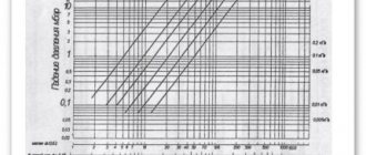
Schedule:
As can be seen from the graph, as the temperature increases, the kinematic viscosity decreases, which means that the resistance to water movement decreases. This means that with a flow of hot water, the “pressure loss” will be less than with a flow of cold water. If you live in apartment buildings, if you pay attention, the speed and pressure of hot water is always higher than the pressure of cold water. There are exceptions, but in most cases this is true. Now you understand why this is so.
Now let's solve the problem:
Find the pressure loss along the length when water moves through a new cast iron pipe D=500mm at a flow rate Q=2 m3/s, pipe length L=900m, temperature t=16°C.
| Given: D=500mm=0.5m Q=2 m3/s L=900m t=16°С Liquid: H2O Find: h-? |
Video:
Buy the program
Solution: First, let's find the flow rate in the pipe using the formula:
V=Q/ω
Here ω
— cross-sectional area of the flow. Found by the formula:
ω=πR2=π(D2/4)=3.14*(0.52/4)=0.19625 m2
V=Q/ω=2/0.19625=10.19 m/s
Next, we find the Reynolds number using the formula:
Re=(V*D)/ν=(10.19*0.5)/0.00000116=4 392 241
ν=1.16*10-6=0.00000116. Taken from the table. For water at a temperature of 16°C.
Δe=0.25mm=0.00025m. Taken from the table for a new cast iron pipe.
Next, we check the table where we find the formula for finding the coefficient of hydraulic friction.
λ=0.11(Δe/D)0.25=0.11*(0.00025/0.5)0.25=0.01645
Next we finish with the formula:
h=λ*(L*V2)/(D*2*g)=0.01645*(900*10.192)/(0.5*2*9.81)=156.7 m.
Answer: 156.7 m = 1.567 MPa.
I also want to draw your attention to the fact that in the problem we considered a pipe that has a horizontal position along its entire length.
Let's look at an example where a pipe goes up at a certain angle.
In this case, we need to add the height (in meters) to the pressure loss to the usual problem. If the pipe goes downhill, then it is necessary to subtract the height.
We looked at the pressure loss along the length of the pipeline; there are also local resistances in the form of narrowing and turns, which also affect the pressure loss. They will be described in my other articles. And I will definitely prepare an article on how to select a pump based on pressure in order to meet the fluid flow requirements, depending on pressure losses. If something is not clear, write in the comments, I will definitely answer!
To avoid doing all the math manually, I prepared a special program:
Next article: Local hydraulic resistances
| Like |
| Share |
| Comments (+) [ Read / Add ] |
All about the country house Water supply Training course. Automatic water supply with your own hands. For Dummies. Malfunctions of the well automatic water supply system. Water wells Well repair? Find out if you need it! Where to drill a well - outside or inside? In what cases does cleaning a well make no sense Why pumps get stuck in wells and how to prevent it Laying a pipeline from a well to a house 100% Protecting the pump from dry running Heating Training course. Do-it-yourself water heated floor. For Dummies. Warm water floor under laminate Educational Video course: According to HYDRAULIC AND THERMAL CALCULATIONS Water heating Types of heating Heating systems Heating equipment, heating batteries Heated floor system Personal article on heated floors Operating principle and operating diagram of a heated water floor Design and installation of a heated floor Do-it-yourself water heated floor Basics materials for heated water floors Installation technology of water heated floors System of heated floors Laying step and methods of laying heated floors Types of water heated floors All about coolants Antifreeze or water? Types of coolants (antifreeze for heating) Antifreeze for heating How to properly dilute antifreeze for the heating system? Detection and consequences of coolant leaks How to choose the right heating boiler Heat pump Features of a heat pump Heat pump operating principle About heating radiators Methods of connecting radiators. Properties and parameters. How to calculate the number of radiator sections? Calculation of thermal power and number of radiators Types of radiators and their features Autonomous water supply Scheme of autonomous water supply Construction of a well Cleaning a well with your own hands Experience of a plumber Connecting a washing machine Useful materials Water pressure reducer Hydraulic accumulator. Operating principle, purpose and configuration. Automatic air release valve Balancing valve Bypass valve Three-way valve Three-way valve with ESBE servo drive Thermostat for radiator Manifold servo drive. Selection and connection rules. Types of water filters. How to choose a water filter for water. Reverse osmosis Sludge filter Non-return valve Safety valve Mixing unit. Principle of operation. Purpose and calculations. Calculation of the CombiMix Gidrostrelka mixing unit. Operating principle, purpose and calculations. Indirect heating storage boiler. Principle of operation. Calculation of a plate heat exchanger Recommendations for the selection of PHE when designing heat supply facilities About contamination of heat exchangers Indirect water heating water heater Magnetic filter - protection against scale Infrared heaters Radiators. Properties and types of heating devices. Types of pipes and their properties Indispensable tools for a plumber Interesting stories A scary tale about a black installer Water purification technologies How to choose a filter for water purification Let's think about sewerage Sewage treatment plants in a rural house Tips for a plumber How to evaluate the quality of your heating and plumbing system? Professional recommendations How to choose a pump for a well How to properly equip a well Water supply for the garden How to choose a water heater An example of installing equipment for a well Recommendations for the configuration and installation of submersible pumps What type of water supply accumulator should you choose? Water cycle in an apartment - vent pipe Removing air from a heating system Hydraulics and heating engineering Introduction What is hydraulic calculation? Discrepancy in hydraulic calculation Physical properties of liquids Hydrostatic pressure Let's talk about resistance to the passage of liquid in pipes Modes of fluid movement (laminar and turbulent) Hydraulic calculation for pressure loss or how to calculate pressure loss in a pipe Local hydraulic resistance Professional calculation of pipe diameter using formulas for water supply How to choose a pump according technical parameters Professional calculation of water heating systems. Calculation of heat loss of the water circuit. Hydraulic losses in a corrugated pipe Heat engineering. Author's speech. Introduction Heat transfer processes Thermal conductivity of materials and heat loss through the wall How do we lose heat with ordinary air? Laws of thermal radiation. Radiant warmth. Laws of thermal radiation. Page 2. Heat loss through a window Factors of heat loss at home Start your own business in the field of water supply and heating systems Question on hydraulic calculations Designer of water heating Pipe diameter, flow speed and coolant flow. We calculate the diameter of the heating pipe. Calculation of heat losses through the radiator. Power of the heating radiator. Calculation of the power of radiators. Standards EN 442 and DIN 4704 Calculation of heat loss through building envelopes Find heat loss through the attic and find out the temperature in the attic Selecting a circulation pump for heating Transfer of thermal energy through pipes Calculation of hydraulic resistance in a heating system Distribution of flow and heat through pipes. Absolute schemes. Calculation of a complex associated heating system Heating calculation. Popular myth Calculation of heating of one branch along the length and KMS Calculation of heating. Selection of pump and diameters Heating calculation. Two-pipe dead-end Heating calculation. Single-pipe sequential heating calculation. Two-pipe associated Calculation of natural circulation. Gravity pressure Calculation of water hammer How much heat is generated by pipes? We are assembling a boiler room from A to Z... Heating system calculation Online calculator Calculation program Heat loss of the room Hydraulic calculation of pipelines History and capabilities of the program - introduction How to make a calculation of one branch in the program Calculation of the KMS angle of the outlet Calculation of the KMS of heating and water supply systems Pipeline branching - calculation How to calculate in the program single-pipe heating system How to calculate a two-pipe heating system in a program How to calculate radiator flow in a heating system in a program Recalculation of radiator power How to calculate a two-pipe associated heating system in a program. Tichelman loop Calculation of a hydraulic separator (hydraulic arrow) in the program Calculation of a combined circuit of heating and water supply systems Calculation of heat loss through enclosing structures Hydraulic losses in a corrugated pipe Hydraulic calculation in three-dimensional space Interface and control in the program Three laws/factors for selecting diameters and pumps Calculation of water supply with self-priming pump Calculation of diameters from the central water supply Calculation of water supply for a private house Calculation of a hydraulic arrow and collector Calculation of a hydraulic arrow with many connections Calculation of two boilers in a heating system Calculation of a single-pipe heating system Calculation of a two-pipe heating system Calculation of a Tichelman loop Calculation of a two-pipe radial distribution Calculation of a two-pipe vertical heating system Calculation of a single-pipe vertical heating system Calculation of a warm water floor and mixing units Recirculation of hot water supply Balancing adjustment of radiators Calculation of heating with natural circulation Radial distribution of a heating system Tichelman loop - two-pipe associated Hydraulic calculation of two boilers with a hydraulic arrow Heating system (not Standard) - Another piping scheme Hydraulic calculation of multi-pipe hydraulic arrows Radiator mixed system heating - passing from dead ends Thermoregulation of heating systems Pipeline branching - calculation Hydraulic calculation for pipeline branching Calculation of a pump for water supply Calculation of warm water floor contours Hydraulic calculation of heating. Single-pipe system Hydraulic heating calculation. Two-pipe dead-end Budget option for a single-pipe heating system for a private house Calculation of the throttle washer What is KMS? Calculation of a gravity heating system Designer of technical problems Extension of a pipe Requirements SNiP GOSTs Requirements for a boiler room Question for a plumber Useful links for a plumber - Plumber - ANSWERS!!! Housing and communal problems Installation work: Projects, diagrams, drawings, photos, descriptions. If you're tired of reading, you can watch a useful video collection on water supply and heating systems
TANK STRUCTURES
7.31. Hydraulic testing for water tightness (tightness) of capacitive structures must be carried out after the concrete has reached its design strength, after they have been cleaned and washed.
Waterproofing and filling of tank structures with soil should be carried out after obtaining satisfactory results of hydraulic testing of these structures, unless other requirements are justified by the design.
7.32. Before conducting a hydraulic test, the tank structure should be filled with water in two stages:
first – filling to a height of 1 m with exposure for 24 hours;
the second is filling to the design level.
A tank structure filled with water to the design level should be kept for at least three days.
7.33. A tank structure is recognized as having passed the hydraulic test if the loss of water in it per day does not exceed 3 liters per 1 m2 of the wetted surface of the walls and bottom, no signs of leakage are found in the seams and walls and no soil moisture is detected at the base. Only darkening and slight sweating of individual places is allowed.
When testing the water resistance of tank structures, the loss of water due to evaporation from the open water surface must be taken into account additionally.
7.34. If there are jet leaks and water leaks on the walls or soil moisture at the base, the capacitive structure is considered to have failed the test, even if the water loss in it does not exceed the norm. In this case, after measuring the water loss from the structure when it is completely flooded, the areas to be repaired must be recorded.
After eliminating the identified defects, the tank structure must be retested.
7.35. When testing tanks and containers for storing aggressive liquids, water leakage is not allowed. The test should be carried out before applying the anti-corrosion coating.
7.36. Pressure channels of filters and contact clarifiers (prefabricated and monolithic reinforced concrete) are subjected to hydraulic testing with the design pressure specified in the working documentation.
7.37. The pressure channels of filters and contact clarifiers are recognized as having passed the hydraulic test if, upon visual inspection, no water leaks are detected in the side walls of the filters and above the channel and if within 10 minutes the test pressure does not decrease by more than 0.002 MPa (0.02 kgf/cm2) .
7.38. The drainage tank of cooling towers must be waterproof, and during hydraulic testing of this tank on the inner surface of its walls, darkening or slight sweating of individual places is not allowed.
7.39. Drinking water reservoirs, settling tanks and other capacitive structures after the installation of floors are subject to hydraulic testing for water tightness in accordance with the requirements of paragraphs. 7.31-7.34.
The drinking water reservoir, before waterproofing and backfilling with soil, is subject to additional testing for vacuum and excess pressure, respectively, with vacuum and excess air pressure in the amount of 0.0008 MPa (80 mm water column) for 30 minutes and is recognized as having passed the test if the values are accordingly vacuum and excess pressure in 30 minutes will not decrease by more than 0.0002 MPa (20 mm water column), unless other requirements are justified by the design.
7.40. The digester (cylindrical part) should be subjected to hydraulic testing in accordance with the requirements of paragraphs. 7.31-7.34, and the ceiling, metal gas cap (gas collector) should be tested for tightness (gas tightness) pneumatically to a pressure of 0.005 MPa (500 mm water column).
The digester is maintained under test pressure for at least 24 hours. If defective areas are detected, they must be eliminated, after which the structure must be tested for pressure drop for an additional 8 hours. The digester is recognized as having passed the leak test if the pressure in it does not decrease within 8 hours more than 0.001 MPa (100 mm water column).
7.41. The caps of the drainage and distribution system of filters, after their installation, before loading the filters, should be tested by supplying water with an intensity of 5-8 l/(s×m2) and air with an intensity of 20 l/(s×m2) with three repetitions of 8-10 minutes. Defective caps discovered in this case must be replaced.
7.42. Before being put into operation, completed pipelines and household and drinking water supply structures are subject to rinsing (cleaning) and disinfection by chlorination, followed by rinsing until satisfactory control physical, chemical and bacteriological analyzes of water are obtained that meet the requirements of GOST 2874-82 and the “Instructions for monitoring the disinfection of household – drinking water and disinfection of water supply facilities with chlorine during centralized and local water supply” of the USSR Ministry of Health.
7.43. Washing and disinfection of pipelines and drinking water supply structures must be carried out by the construction and installation organization that carried out the laying and installation of these pipelines and structures, with the participation of representatives of the customer and the operating organization with control carried out by representatives of the sanitary and epidemiological service. The procedure for washing and disinfecting pipelines and domestic water supply structures is set out in recommended Appendix 5.
7.44. A report must be drawn up on the results of the washing and disinfection of pipelines and domestic and drinking water supply structures in the form given in mandatory Appendix 6.
The test results of capacitive structures should be documented in an act signed by representatives of the construction and installation organization, the customer and the operating organization.