How to calculate the cross-sectional area of a pipe - simple and proven methods
Calculating the cross-section of a pipe is quite simple, because there are a number of standard formulas for this, as well as numerous calculators and services on the Internet that can perform a number of simple actions. In this material we will talk about how to calculate the cross-sectional area of a pipe yourself, because in some cases it is necessary to take into account a number of structural features of the pipeline.
Calculation formulas
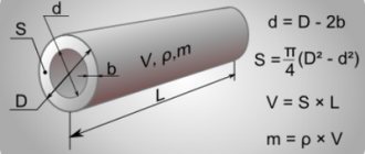
When carrying out calculations, it must be taken into account that the pipes are essentially cylindrical. Therefore, to find their cross-sectional area, you can use the geometric formula for the area of a circle. Knowing the outer diameter of the pipe and the thickness of its walls, you can find the internal diameter indicator that will be needed for calculations.
The standard formula for the area of a circle is:
π – constant number equal to 3.14;
S is the cross-sectional area of the pipe, calculated for the internal diameter.
We climb into standards
Frankly, there is a way to avoid any complex calculations in principle. The fact is that the weight of a linear meter of pipe is specified in the assortment table, which, in turn, is part of the standard for each type of pipe .
Thus, steel rectangular pipes are produced in accordance with GOST 8645-68. The treasured pipe measuring 180x145x20 millimeters is located at the very end of the table (it is in the appendix to the article), in the “special sizes” section. And what do we see there?
A linear meter of pipe weighs 84.1 kg. Accordingly, 18 kilometers of pipe will have a mass of 18000 * 84.1 = 1513800 kg, or 1513.8 tons.
There is a discrepancy with both results. We tear out the hair on our bodies and bang our heads against the wall in despair.
He also calculated the mass of the pipe in different ways
Calculation procedure
Since the main task is to find the cross-sectional area of the pipe, the basic formula will be slightly modified.
As a result, the calculations are performed as follows:
D – value of the external section of the pipe;
Please note that the more digits of π you plug into your calculations, the more accurate they will be.
Let us give a numerical example of finding the cross section of a pipe with an outer diameter of 1 meter (N). In this case, the walls have a thickness of 10 mm (D). Without going into details, let's take the number π equal to 3.14.
So the calculations look like this:
S=π×(D/2-N) 2 =3.14×(1/2-0.01) 2 =0.754 m 2.
conclusions
There are actually several of them.
- Different calculation methods give quite a noticeable scatter of results . If, when calculating the strength of metal structures, the safety margin in any case exceeds the deviation from the calculated weight, then when purchasing a large number of pipes, there is a real chance of making an error up or down, which will lead to a re-purchase or budget overrun;
- When purchasing pipes, it is wiser to rely on figures from GOST . Exclusively because in a controversial situation your position will be more reasoned: if, according to GOST, there should be 100 meters in a ton of pipe, but it turned out to be 110, it means that the pipe manufacturer has deviated from the standards for the sake of economy.
- If purchasing an additional pipe is not a big problem, it is better to focus on the minimum of the calculated values . Just for reasons of economy.
Good luck!
Application
Did you like the article? Subscribe to our Yandex.Zen channel
Hydrodynamics. Hydraulic radius and diameter.
The hydraulic radius (R) is usually used to denote the ratio of the living cross-sectional area to the wetted perimeter. So, for example, for a round pipe operating with a full cross-section, the hydraulic radius is equal to one fourth of its diameter. The formula takes the form:
Live section (w) is usually denoted as a cross-section of a flow perpendicular to all stream lines .
For example, when considering a round tube with diameter d, and the entire cross-section is filled with liquid, the live cross-section is represented by the area of the circle :
Wetted perimeter (χ) is that part of the perimeter of the live section that borders on solid walls, forming a wetted surface . For example, for a channel, the entire lateral surface of the flow , without a free plane, where the liquid borders the gaseous medium .
For a round pipe operating with a full cross-section, the wetted perimeter will be equal to the circumference , which means the formula will take the form:
For a round empty pipe, the formula takes the form:
The hydraulic diameter (D) is usually used to denote the ratio of four times the area of the live section to the wetted perimeter:
Source
Types of pipe sections.
To lay water supply or sewerage systems in construction, pipes of various shapes and sections . For classic water supply, round, square, rectangular, triangular, elliptical and other pipes can be used. For sewerage, pipes of round, semicircular, elliptical, semi-elliptical, ovoid, rectangular, trapezoidal and other shapes and sections are used.
The most popular are pipes with a round cross-section . The production of such pipes is low-cost, they have good technical characteristics, as well as a number of excellent technical and operational qualities.
To calculate the weight of a pipe or the length of a pipe, you can use a pipe calculator.
The types of pipeline sections can be different:
- a) - Round;
- b) - Square;
- c) - Rectangular;
- d) - Triangular;
- e) - Ellipsoid;
- e) - Ringed;
- a, b - Linear dimensions.
The following are the cross-sectional shapes of gravity pipes and channels, such as:
- a) - Round,
- b) - Semicircular,
- c) - Tent,
- d) - Banquet,
- d) - Ovoid (ovonal),
- e) - Elliptical,
- g) — Semicircular with straight inserts;
- e) - Ovoid inverted,
- i) - Tray,
- j) - Pentagonal,
- l) - Rectangular,
- m) - Trapezoidal
Calculation of pipeline cross-section.
The formula for the cross-sectional area of a pipe will depend on what the shape of this section is. To calculate the cross-section of a pipeline, it is necessary to calculate the area of a circle with a diameter that is equal to the outer diameter of the pipe, and then subtract the thickness of its walls.
The area of a circle is calculated by the formula: S = Pi*(R^2) or S=Pi*(D/2-N)^2,
- R is the radius of the circle, equal to half its internal diameter;
- S is the desired value;
- Pi is the number pi, which is usually rounded to 3.14.
- D and N are the outer diameter and wall thickness of the pipe.
As an example, we calculate the internal cross-sectional area of a round pipeline with an internal diameter of 100 mm.
The radius of this pipe will be 50 mm, or 0.05 m.
The area of the pipe will be 3.14 x 0.05^2 = 0.00785 m2.
Attention: when calculating the permeability of gravity pipelines (for example, domestic sewage), take into account not the total, but the so-called live flow cross-section , which is limited by the average water level.
Live section - lattice
The authors studied the conditions for the formation of a gas cushion under the sectioning grid and the influence of the live section of the redistribution grids on the uniformity of fluidization.
To reduce losses through failure when there is a large amount of fines in the peat, a reduction in the open cross-section of the grate and a corresponding increase in the blast pressure are required.
Consideration of the data in table. 5 shows that the depth of destruction practically does not depend on the active cross-section of the lattice, however, the degree of saturation with hydrogen increases, which makes it possible to increase the yield of diesel fuel with a given iodine number.
| Diagram of a firebox with a simple grate and the design of the grates used. |
The sum of the areas of the holes in the grate for the passage of air to the fuel layer is called the live cross-section of the grate. In grates designed for burning large lump fuel, the live cross-section is 25 - 30% of the grate area.
The ratio of the total area of air gaps or holes in the grille to its other area is called the live section of the grille. There are gratings with a small (5 - 15%) and large (15 - 40%) open section. The required size of the open section is determined by the properties of the fuel being burned.
With a decrease in the number of holes in the lattice from 223 to 61 with the same open cross-sectional area of the lattice, the height of the pillow remains almost constant. It also does not change with increasing height of the fixed layer on the redistribution grid from 270 to 350 mm.
Losses with dip Q p relate to grates and depend mainly on the design and open cross-section of the grate.
The gas velocity in the section of the apparatus is usually taken within the range of 1 - 3 m / s, and the live cross section of the grating is chosen so that the gas velocity in the holes is 6 - 13 m / s. Reducing the speed leads to a violation of the integrity of the foam layer; increasing the speed above the specified limits sharply increases losses due to splashes.
The diameter of the hole in the upper grille is 3 mm, the distance between the holes and their number are determined based on ensuring that the live cross-section of the grille is within 5 - 7% of its total area. Thus, the speed of air passage through the grille openings is approx.
| Painting booth with bottom suction and top air supply.| Diagram of the VTSNIIOT dust collector for sharpening machines, hopper of the first cleaning stage. 3 - suction pipe. 4 - fixed shield. 5 — adjustable shield. |
The product is installed at such a height above the grille that the speed of air leakage is no greater than the speed of its movement in the live section of the grille. Supply air is supplied from above evenly over the entire area of the chamber ceiling. A false ceiling equipped with filter cassettes should be used.
The ratio of the area of all gaps R in the grate through which air enters the layer to the entire area of the grate is called the live cross-section of the grate and is usually expressed as a percentage. The required size of the live cross-section of the grate depends on the type of fuel burned and the size of the pieces. Thus, when burning sod peat and firewood, beam grates are used.
Analyzing the experimental data, it can be seen that there are certain patterns in the decrease in layer resistance with an increase in the speed of the fluidizing agent and with a decrease in the open cross-section of the lattice.
| Industrial installation for dehydration of sodium sulfate waste solutions. |
Features of pipes with different sections.
Round pipes are very easily cleaned of sediment formed by hydraulic means using balls and cylinders
As the diameter of a circular pipe increases, soil pressure and temporary external loads increase rapidly. To reduce the force in the walls of the pipes, the vault is given a semi-elliptical cross-section .
an ovoid cross-section can be used ; a pipe of such a cross-section is capable of high static and dynamic loads, but such a pipe also has disadvantages: installation of pipes with such a cross-section requires a greater channel height and laying depth than for round-section pipes with the same throughput.
In addition, in pipes with an elliptical cross-section, sediment forms much faster, which settles on the walls. In places where quicksand are present and the soil is very wet, tray-shaped . This allows sewer networks to be laid at a shallower depth.
Source
How to calculate the cross-sectional area of a pipe by diameter
A pipe is a long, hollow industrial product based on a hollow profile of constant cross-section, designed for transporting liquids or gases.
A pipe section is an image of a figure formed by cutting a pipe with a plane in the transverse direction.
Formula for calculating the cross-sectional area of a pipe:
Dн – outer diameter of the pipe; Dв – internal diameter of the pipe.
You can quickly perform this mathematical operation using our online program. To do this, enter the initial value in the appropriate field and click the button.
This page provides the simplest online calculator for calculating the cross-sectional area of a pipe if the outer and inner diameters of the pipe are known. With this calculator you can calculate the cross-sectional area of a pipe in one click.
In our time, the unification of countries into one world community significantly increases the interdependence of the economies of different countries from each other. This leads to global movement in time and space of people, services, goods, and raw materials. Hence the significant increase in the role of transport in its various forms and types.
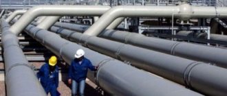
One of the highly specialized types of transport are pipelines, the advantages of which are indisputable and obvious. For example, if you calculate the throughput, then the cost of a pipeline is more than two times less than a railway or road. When transporting liquids or gases, losses in pipelines are 2-3 times less compared to other types of transport. And in heating, sewerage, water supply and ventilation systems, pipelines play a dominant role. That is why correctly calculating the area of the pipe and the entire pipeline as a whole becomes an urgent task both to save material and money, and to maximize the use of all the functionality of the pipeline network. Moreover, the industrial industry, through its distribution network and online stores, provides the widest range of everything necessary for this type of transport.
BASIC DEFINITIONS
Let's take any point in the fluid flow. A liquid flows through this point, having a certain direction and speed of movement. If at all points of the flow the direction and speed of fluid movement do not change over time, the movement is steady
.
If this condition is not met, the movement is unsteady
.
Let us consider a fluid moving in a flow. Let's take any arbitrary point and plot the velocity vector. At a small distance from it, on the velocity vector, we will plot the next point ( strictly speaking, this distance should be infinitesimal
).
But at this point both the direction of movement and the speed will be different compared to the first point. If we try to repeat the procedure similar to obtaining the first segment, we will see that the second segment will not be a continuation of the first. This construction can be continued, as a result of which we get the curve drawn above. This curve will be called a streamline
.
Current line
– a line whose tangents coincide with the velocity vectors.
It is necessary to distinguish a streamline from a trajectory
liquid particles. A streamline is a snapshot of a flow. If the motion is steady, then the particle will exactly follow the streamline. And if not? At the next moment in time, when the particle approaches the next point, the velocity vector in it will be different and the particle will continue its path in a different direction and at a different speed.
Live section
– a section drawn perpendicular to the velocity vector and lying inside the flow. In the general case, the living cross-section in a flow is a curved surface, but in practical calculations, if the flow changes smoothly, the cross-section is considered flat.
Above are examples of live sections, where arrows indicate velocity vectors, and dotted lines indicate live sections.
Let's imagine a fluid flow, draw a live section in which we select an elementary area dw. We will draw streamlines through all points of the site.
Live
section
Elementary trickle
Elementary
dw site
A fluid flow consists of a set of elementary streams.
The concept of an elementary stream allows us to obtain the basic dependencies for calculating the parameters of a moving fluid. It turned out to be possible to simplify the problem thanks to the following properties of an elementary stream
:
1. Since the area dw is elementary, the values of velocity and pressure for all points of the elementary cross section of the stream can be considered the same. This property makes it possible not to take into account the complex nature of changes in speed and pressure within the living cross section of an elementary stream
.
2. Since the side surface of the stream is formed by stream lines along which other particles slide, penetration of other liquid particles through the side surface is impossible. The elementary stream is, as it were, enclosed in waterproof walls that have no thickness. This property makes it easy to implement the laws of conservation of mass and energy in calculations without complicating the solution by taking into account mass transfer processes
.
Consumption.
Fluid flow rate is the volume of fluid passing per unit time through the open section.
Q= L3t, [m3/s]
Since the velocities at different points in the flow are different, the flow rate is generally found as:
As noted above, the velocities along the live cross section of the flow are different and their determination is a rather difficult task. Practical calculations, as a rule, are performed using integral indicators and are made for the entire object (in this case, fluid flow) as a whole without specifying the microstructure. Among such indicators, average speed is most often used in hydraulics courses.
average speed
is the average flow velocity for a given live section and is found as:
V = Qw
In a simplified sense, this is a graph of velocity changes over a cross section. Below is an example of such a diagram.
vҐ _
v4
v3
v2
v1
v
Pipeline characteristics
Correctly calculating the characteristics of pipelines will help you save money and get maximum opportunities when installing both main and conventional water or heating pipelines.
What can you save on or get maximum opportunities if you correctly calculate the pipe, both main and ordinary home, water supply or heat? Knowing these winning opportunities and taking advantage of them is a formula for success! Let's look at them in more detail:
- The permeability of the pipeline - this indicator affects both the consumption of transported material and the cost of the structure itself. The main indicator here is the cross-sectional area. To calculate it, you need to know the outer diameter and wall thickness of the pipe.
- Heat loss is an important pipeline parameter when transporting coolant (water) from a heating point to heating devices. The formula for calculating heat loss, along with many physical quantities, includes the diameter and length of the pipe.
- The amount of heat-insulating material - an accurate calculation of the surface area of the pipeline is required for maximum savings in material and costs.
- Anti-corrosion coating of the pipeline - correct calculation of the covered area leads to savings in paint or bitumen varnish.
- The roughness of the internal surface is an indicator that affects the flow rate in the pipe. The lower the roughness, the lower the resistance of the pipeline walls and the higher the flow speed. A variable indicator, depending both on the geometric dimensions of the pipe and on the process of overgrowing of its transverse lumen with rust and mineral deposits.
Potential flow - ideal fluid
The potential flow of an ideal fluid smoothly flowing around any body determines such a distribution of local normal pressures over the surface of the body that the resultant of these pressures does not produce a component in the direction of the velocity vector KOS. Euler's paradox contradicts everyday experience, indicating at the same time that the hypothesis of potentiality and continuity of flow does not take into account important phenomena in real fluid flows.
Consider the potential flow of an ideal fluid in the elbow shown in Fig. XIV.6. Fluid particles moving along curved trajectories are influenced by centrifugal forces of inertia.
So, if a potential flow of an ideal fluid, having a speed at infinity equal to Vw, smoothly flows around a certain contour, and the circulation of the speed around this contour is equal to G, then the lifting force of the contour is equal in magnitude to the product of the fluid density by the circulation and the flow velocity at infinity. To determine the direction of the lifting force, it is enough to rotate the flow velocity vector at infinity by 90 against the direction of the flow caused by the attached vortex.
In this case, the potential flow of an ideal fluid outside the boundary layer cannot be modeled as a smooth flow pattern and must be replaced by some other scheme that meets a particular problem.
Note that the drag force for a potential flow of an ideal fluid is zero not only when flowing around a round cylinder, but also for any other body, regardless of its shape.
The absence of a drag force for bodies flowing around a potential flow of an ideal fluid is called the Euler-D'Alembert paoadox in hydrodynamics.
The absence of a drag force for bodies streamlined by a potential flow of an ideal fluid is called the Euler-Dalambgra paradox in hydrodynamics.
This distribution can be found by solving the problem of a potential flow of an ideal fluid flowing around a body. Due to the fact that the boundary layer is very thin, the found velocity distribution can be attributed to the outer boundary of the layer.
Let us consider the flow of a potential ideal fluid flow around a cylinder of radius r1 with two symmetrically located vortices. Let us take the centers of symmetrically located vortices in the position where a small change in circulation leads to the separation of one of the vortices.
Let there be an infinitely deep potential flow of an ideal fluid moving above the bottom (x axis) with a speed V in - oo; let a jet flow into this flow from the bottom (at point x 0) with speed Vz, directed at an angle a to the bottom, and it is necessary to determine how this jet will move.
So, for the case of converging flow in a diffuser, the flow at high Reynolds numbers differs very little from the potential flow of an ideal fluid. Only near the walls does a very rapid change in velocity occur from values corresponding to the potential flow of an ideal fluid to zero values required by the conditions for the adhesion of a viscous fluid to the walls
Let us pay attention to the fact that the converging flow in the diffuser occurs in the direction of the pressure drop. While at low Reynolds numbers the converging and diverging flows in the diffuser are of the same nature, at large Reynolds numbers the flows are completely different in nature, namely, the converging flow everywhere, except in the immediate vicinity of the walls, differs little from the potential flow, while the divergent flow differs sharply from the potential flow.
The first attempt to construct a vortex theory of pressure resistance belongs to Th. The oncoming potential flow of an ideal fluid smoothly flows around the front (frontal) part of the contour (in Fig.
The first is directly adjacent to the streamlined body and is usually called the boundary layer. This is a very thin layer in which all the influence of viscosity is concentrated. The second section is the wake behind the streamlined body, the third is the entire remaining region in which the influence of viscosity does not affect, and, therefore, it can be considered as a region of potential flow of an ideal fluid.
The first is directly adjacent to the streamlined body and is usually called the boundary layer. This is a very thin layer in which all the influence of viscosity is concentrated. The second section is the wake behind the streamlined body, the third is the entire remaining region, in which the influence of viscosity is not felt, and, therefore, it can be considered as a region of potential flow of an ideal fluid.
Why you need to know this
Below we will consider the situation, at a time when these parameters in most cases invariably need to be taken into account in work:
- Knowledge of the area formula will be necessary when calculating the heat transfer of a heated floor or heating register . Data can be taken based on a non-specialized area that transfers heat to the air in the room from a working fluid of a certain temperature.
- The second option is the opposite situation, which is also seen quite often . Especially if you need to calculate heat loss along the entire length of the pipeline to the heating device. When calculating the number and size of convectors, radiators and other devices, the instructions require you to know exactly how many calories they can produce. The data is determined taking into account the surface area of the pipeline transporting water.
- Once you know how to calculate the surface area of a pipe, you can purchase the correct amount of insulation . Often the length of the heating main is tens of kilometers, based on this, the correct data will help companies save significant funds.
When it might come in handy
Brake fluid quality testers
You should start by identifying cases where such calculations may be useful:
They can be useful if it is necessary to calculate heat transfer through a pipeline. All this is calculated based on the surface area that transfers thermal energy from the coolant to the environment. It is often necessary to determine the loss of thermal energy on the way to the heating device. All this will allow you to determine the required number and dimensions of radiators. To do this, we need to know how many calories we have at our disposal. The calculation is also made based on the area of the corresponding surface of the pipeline through which the coolant is transported from the elevator unit.
In order to determine the required volume of thermal insulation material, the external surface area should also be determined. In this case, the more accurate the calculation, the higher the savings on the purchase of material. Since the length of the heating main can be several kilometers, such savings can amount to a large amount.
The calculation will also be useful in determining the costs associated with the purchase of coloring material. Determination of the pipeline area for painting along with calculation of paint consumption per square meter. m. allow you to accurately obtain the amount of total costs. An interesting offer for beginners. With us you can get the most profitable 1xbet promotional code for today absolutely free when registering with the company. Just go from our portal to 1xbet and create a new account. You will be given a 1xbet promotional code valid for today upon registration, which will be credited to your base account with up to 6,500 rubles. The bonus amount is equal to 100% of the amount made on the first deposit. If you deposited 100 rubles into your account, then the code will give you the same amount. The 1xBet promo code is a good opportunity to make a free bet. Find out how to get a promotional code and use it for its intended purpose when placing bets in the 1xBet mirror!
Determining the area of the internal surface of the pipeline will be useful in calculating its maximum permeability. This will allow you to avoid exceeding the costs incurred for the purchase of pipes over the required ones. When designing large communication networks, this will reduce the amount of money spent.
Calculation of pipe parameters
As we can see, for the various pipeline parameters used, the common ones are the calculation of the cross section, external and internal surface areas of the pipe.
Let us dwell on the methods for calculating these quantities (independent calculation requires knowledge in secondary school). Note that all parameters can be calculated either using a regular calculator or using special online programs.
Section calculation
Middle school geometry problem. It is necessary to calculate the area of a circle with a diameter equal to the outer diameter of the pipe, subtracting the thickness of its walls.
The area of a circle is calculated by the formula S = Pi*(R^2) (or Pi*R*R), where R is the radius of the circle, equal to half the diameter.
All parameters can be calculated either using a regular calculator or using special online programs.
Thus, the cross-sectional area of the pipe looks like this: S=Pi*(D/2-N)^2, where S is the cross-sectional area, Pi is the number “pi” (=3.14159...), D and N are the outer diameter and pipe wall thickness. The accuracy of the result depends on the number of decimal places in pi.
Let us give an example of calculating an internal section with an outer diameter of 1 m and walls 10 mm thick (0.01 m). If we take 2 decimal places in pi to simplify calculations, the formula will look like this:
Pipe outer surface area
The surface of a cylinder is a rectangle, one side of which is the circumference of the cylinder, and the second side is the length of the cylinder itself. And to find out the area of a rectangle, you need to calculate the product of its two sides (i.e., the product of length and width).
The problem is purely geometric. The surface area on the outside is nothing but the surface area of the cylinder. And the surface of a cylinder is a rectangle, one side of which is the circumference of the cylinder, and the second side is the length of the cylinder itself. And to find out the area of a rectangle, you need to calculate the product of its two sides (i.e., the product of length and width).
How to make a calculation
Calculating the cross-section
Determining the cross-section of a pipe is a simple geometric task. To do this, you should first use the formula for the area of a circle:
Sн= π•Rн^2, (1)
where Rн is the outer radius of the pipe, equal to half the outer diameter.
Thus, we determine the area of the circle formed by the outer diameter.
Now let's determine the area of the circle formed by the inner diameter of the pipe. To do this, it is necessary to determine the internal radius, which is determined by the following formula:
Rin=Rn-?, (2)
Where ? – pipe wall thickness.
Having determined the area of the inner circle Sе similarly to formula (1), we calculate the cross-sectional area using the formula:
Ssec=Sn?-S?in.
All actions can be summarized in a simplified formula for determining the cross-sectional area:
Ssec=?•(?D_н/2?^2- ??/2?^2 ).
As an example, let us determine the cross-sectional area, the outer diameter of which is 1 meter and the wall thickness is 10 mm.
Ssec=3.14•(?1/2?^2-?0.01/2?^2)=0.75 m^2.
We calculate the area of the external surface
This calculation is also a geometric problem. If you unfold the pipe, you get a rectangle. Its width is equal to the circumference of the outer wall of the pipe, and its length is equal to the length.
You can calculate the circumference using the following formula:
L=?•D_н.
Then the development area of the pipe will be calculated by the formula:
S=?•D_н•L_tr,
where Ltr is the length of the pipe.
As an example, let’s calculate the surface area for painting a heating main, the length of which is 10 km, and the outer diameter is 1 meter.
S=3.13•1•10000=31416 m^2.
If we talk about the amount of thermal insulation material, then when calculating, we should take into account the thickness of the mineral wool layer.
Then the formula will take the form:
S=?•?(D?_н+?2•??_(в))•L_tr,
where ?_in is the thickness of the mineral wool layer.
In reality, less material will be wasted for thermal insulation, since it is overlapped.
We calculate the area of the internal surface
First you need to decide why such a calculation should be carried out. Most often it is needed when calculating the hydrodynamics of coolant movement in a pipe. The inner surface of the pipe is the place where water, as it moves, comes into contact with the pipe. Thus, hydraulic resistance arises, which must be taken into account when calculating the communication network.
It is necessary to remember a number of the following nuances:
- As the pipeline diameter increases, the hydraulic friction of the coolant against the pipe walls decreases. Therefore, with a large diameter and length of the water supply system, the hydraulic resistance of the pipe to the flow of water can be ignored.
- The quality of the surface, its roughness, has a great impact on the value of hydraulic resistance. Moreover, this influence is stronger than the dependence of resistance on the surface area of the inner wall of the pipeline. Thus, a polyethylene pipe has less roughness than a rusty metal pipe. Therefore, the amount of hydraulic resistance in a plastic pipe will be less.
- If non-galvanized steel is used as the material for making the pipe, the surface area of the inner wall changes over time. Rust and mineral deposits are gradually deposited on the walls of such a pipeline. As a result, the internal diameter of the pipe decreases and the hydraulic resistance increases. This effect must be taken into account when designing steel water pipes.
So, in order to calculate the surface area of the inner wall of the pipeline, you should use the following formula:
S=?•?(D?_n-2•?)•L_tr.
As an example, let's calculate a pipe whose diameter is one meter and the wall thickness is 10 mm.
S=3.14•(1-2•0.01)•10000=30788 m^2.
Conclusion
So, the calculations given in the article are not complicated and are accessible to anyone. They will come in handy when designing your own pipeline. In order for the constructed communication to meet the expectations of its performance, the proposed calculations must be made without fail.
How are calculations done?
As you know, a pipe is a cylinder. Consequently, its cross-sectional area is calculated using simple formulas known to us from the geometry course. The main task is to calculate the area of a circle whose diameter is equal to the outer diameter of the product. In this case, the wall thickness is subtracted to obtain the true value.
As we know from the secondary school course, the area of a circle is equal to the product of the number π and the square of the radius:
- R – radius of the calculated circle. It is equal to half its diameter;
- Π – constant equal to 3.14;
- S is the calculated cross-sectional area of the pipe.
Let's start calculating
Since the task is to find the true area, it is necessary to subtract the wall thickness from the obtained value. Therefore, the formula takes the form:
To make the calculations as accurate as possible, you should enter more decimal places in the number π (pi).
For example, you need to calculate the cross-section of a pipe whose outer diameter is 1 meter. The thickness of its walls is 10 mm. (or 0.01 m.). Therefore, we know:
To simplify, let's take π = 3.14. Substitute the values into the formula:
S = π • (D/2 – N) 2 = 3.14 • (1/2 – 0.01) 2 = 0.754 m 2 .
Why is this necessary?
Calculation of metal structures
Before you start manufacturing any metal structure, you need to perform a strength calculation.
- If we are talking about a pipeline, you need to know how often you need to install supports so that the pipe does not sag . Moreover, the mass of the pipeline is not only the weight of the transported liquid, but also the mass of the steel pipes of which it consists.
Calculation of the strength of a metal structure must also take into account its own weight
- When we talk about the load-bearing frame of an office building, sports complex or exhibition hall, we again need to calculate the weight of the structure . After all, not only the people in the building will put pressure on the foundation and supports with their weight. In fact, the weight of the steel frame of a sandwich panel building constitutes the majority of the total weight of the building along with all its contents.
Please note: a channel or I-beam is used as a basis for floors, much more often than pipes (usually square or profile). They provide greater strength at the same specific weight.
Calculation of the number of pipes when purchasing
Suppose you have drawn up a pipeline or metal structure project and calculated that you need to purchase 1200 meters of pipe with a wall thickness of 4 millimeters and an outer diameter of 100 millimeters.
However, a surprise awaits you at the metal warehouse: wholesale batches of pipes are sold not by meters, but by tonnage. If so, the only way out is to recalculate the number of pipes you need from meters to tons.
This device weighs large diameter pipes individually
Inner surface area
This mathematical value allows you to accurately calculate the hydrodynamic values of the supplied substances, based on the physical properties of the structure, irregularities and roughness of the channels.
It should be understood that when calculating values, the following patterns are observed:
- An increase in the internal diameter leads to a weakening of the influence of irregularities and roughness on the permeability of the supplied substance.
- If the material from which the pipe is composed tends to accumulate waste or is prone to corrosion, then it is necessary to regularly recalculate the internal and external diameters. A change of material is necessary after a few years, since during this time severe clogging occurs, due to which the throughput of the pipes sharply decreases.
The formula for calculating the internal surface is as follows:
S=2П(D/2-I)*L, where:
- P - Pythagorean number;
- D is the outer diameter of the pipe;
- I is the thickness of the walls of the structure;
- L is the length of the pipe.
Water volume
Volume of water in a pipe One of the main applied quantities when calculating the internal surface area is the volume of water flowing through the pipe during transportation.
The only reason why it is not included in the general form of calculation is the insufficient range of application, since this physical term is applicable only to pipelines that use water, for example, sewers, water pipes. The most widely used value of water volume is when measuring the heating capacity of pipes. To know exactly how much water to use, you need to use 2 types of formulas:
- S0 is the area of the pipe base;
- H is the height of the structure.
Updraft - liquid
The upward flow of liquid from the well rises through the flushing pipes, passes through the outlet head, and the hoses then enter the receiving tank.
| A projectile with a hydrocyclone sludge catcher. |
The upward flow of liquid passes through a special channel located in the adapter parallel to the slurry-conducting pipe and in close proximity to it.
| Flushing head design b. CISON for backwashing.| Diverter head for backwashing. |
The upward flow of liquid from the well rises through the flushing pipes, passes through the outlet, hose and enters the receiving tank.
| Schematic diagram of a viscometer with a falling ball. |
The ascending flow of liquid lifts ball 1 to the upper position. At the moment the ball touches the upper limiting mesh 6, the pump is turned off, and the ball falls freely in a stationary environment.
The speed of the upward flow of liquid in the annular space must be less than the speed of sedimentation of sand in the same liquid.
In an upward fluid flow from the bottom to the wellhead, the volume fraction of sand in height has a different value, as does the fraction of small particles of sand and clay. It can be assumed that the density of the sand plug when water appears will be greatest in that part of the wellbore where, at the moment the liquid inflow ceased and, therefore, at a vertical flow velocity equal to zero, the highest concentration of small particles of clay and sand was contained.
In this case, the upward flow of liquid keeps the solid particles in suspension, preventing them from settling.
In this case, the upward flow of liquid keeps the solid particles in suspension, preventing them from settling.
In this case, the upward flow of liquid keeps the solid particles in suspension, preventing them from settling.
The valves are kept open by the upward flow of fluid moving relative to the pipes; the closing of the valves must obviously occur at the moment () when the relative speed w becomes equal to zero.
In filters with an upward flow of liquid, the recommended loading size is the same as with a downward flow of liquid, and washing can be water or water-air.
A solid particle in an ascending liquid flow moves upward if the speed of the ascending liquid flow is greater than the settling speed of the solid particle relative to the liquid in the ascending flow.
Some physical features
The cross-sectional area of the pipe determines the speed of movement of liquids and gases that are transported through it. You need to choose the optimal diameter. Internal pressure is no less important. The feasibility of choosing a section depends on its size.
The calculation takes into account not only pressure, but also the temperature of the medium, its nature and properties. Knowing formulas does not relieve you from the need to study theory. Calculation of sewerage, water supply, gas supply and heating pipes is based on information from reference books. It is important that all necessary conditions are met when choosing a section. Its value also depends on the characteristics of the material used.
Source