Hydraulic calculation of pipelines allows you to calculate water flow (throughput), the length of the section, its internal cross-section and pressure drop, and compare with the recommended parameters:
- Losses per 1 m of area, based on the material, are 80 - 250 Pa/m or 8 - 25 mm of water column.
- The maximum water speed for internal diameters varies: 1.5 cm - 0.3 m/s, 2 cm - 0.65 m/s, 2.5 cm - 0.8 m/s, 3.2 cm - 1 m/s s, for other parameters it is limited to 1.5 m/s.
- In fire-fighting pipelines, the maximum speed of water movement is 5 m/s.
Conditional permeability DN
The conditional permeability parameter DN (nominal diameter) is a dimensionless quantity; its numerical value approximately corresponds to the internal cross-section of the pipes (for example, DN 125). The numerical values of the conditional transition are selected to increase the throughput of the pipeline network within the range of 60 - 100% when moving from one conditional throughput to the next.
According to GOST 28338-89, the parameters of conditional cross-country ability (Dn in the past) are selected from the size range:
The values are selected taking into account the elimination of problems regarding the fitting of parts to each other. The nominal diameter based on the parameters of the internal section is selected based on the clear diameter of the pipe.
Calculation of home plumbing
From a practical point of view, pressure in a water supply system is most often associated with the volume of water supplied per unit of time, that is, with the throughput of the water supply branch. In this context, the issue of calculating household water supply will be considered. After studying the passport data of devices and units that consume water, the total consumption is summed up. Then the consumption of all installed and used water taps is added to the resulting figure.
For home water supply running from a well, the choice of pipes depends on the power of the pump
Helpful information! One such plumbing device passes about 5-6 liters of water through itself in one minute.
After this, all the numbers are summed up, and the output is the total water consumption in the house. Taking this data into account, a pipe with a diameter is purchased that will provide the required pressure and, accordingly, the amount of water to all water taps operating simultaneously.
If the home water supply is planned to be connected to the city network, the owner has no choice; he will be forced to use what is available. It’s a different matter if we are talking about a private house powered by a well. Then you should buy a pump that can provide the water supply with pressure that matches the costs. The choice is made according to the passport data of such a unit. The table below will help you determine the diameter.
table 2
| Pipe capacity | Pipe diameter and length | ||
| Throughput, l/min | Pipe diameter | Pipe diameter | Pipeline length, meters |
| 75 | 38 | 32 | More than 30 |
| 50 | 32 | 25 | |
| 30 | 25 | 20 | Less than 10 |
Here are the parameters of only the most commonly used pipe products.
Nominal pressure parameter PN
The value of the nominal pressure PN (the value corresponding to the maximum pressure level of the pumped media at 20 °C) is calculated to determine the long-term operation of a pipeline network with specified parameters. The nominal pressure parameter is a dimensionless value, calibrated based on operating practice.
The nominal pressure parameter for specific pipeline systems is selected based on the actual voltage by determining the maximum value. Fittings and fittings correspond to the data obtained. To ensure normal operation of the systems, the thickness of the pipe walls is calculated based on the nominal pressure.
Definition of indicator
The pressure in the pipeline is usually divided into the following types: working, conditional, test and calculated. Without knowing their differences, it will be difficult to calculate the pressure drop of the fluid transported through the utility lines. Accordingly, when selecting suitable water supply elements, the owner will encounter difficulties that will not allow him to ensure a comfortable stay in the living space.
- Working. This is external or internal, necessarily the maximum excess pressure recorded under standard components of the water transportation process under normal conditions.
- Conditional. This indicator is used when calculating the strength of pipelines (and vessels) that operate under a certain pressure at a water temperature of 20˚C.
- Trial. This simple indicator is measured during a design test. Based on it, the behavior of system elements when pressure changes in the water supply system is monitored. This approach serves as a kind of general insurance before laying a network.
- Calculated. This means the maximum excess pressure in the cavity of the pipeline produced by the substance transported through it. It should be taken into account that not only pipes are affected, but also all elements that make up the engineering communications. It is on the basis of the calculated pressure that the wall thickness of the water pipe is determined. The functionality, as well as the duration of operation of the system and, of course, the safety of the inhabitants of the house depend on this.
The water pressure in the tap depends on the pressure in the plumbing system
Permissible parameters of excess operating pressure pe,zul
Nominal pressure parameters are used for working environments with a temperature of 20°C. As the heating level increases, the ability to withstand loads decreases, which affects the reduction in permissible excess pressure. The pe,zul indicator determines the maximum level of excess voltage allowed when the temperature increases.
Material selection
The selection of material is made based on the characteristics of the media transported through the pipeline line and the operating pressure provided for the system. It is necessary to remember about the corrosive effect of the pumped media in relation to the material of the walls of the pipeline network. Typically, pipes and chemical systems are made of steel. In the absence of high mechanical and corrosive effects, gray cast iron or unalloyed structural steel is used when developing pipes.
At high operating pressure and the absence of loads with corrosion formation, pipes made of high-quality steel or its casting technology are used. When there is a high corrosive effect or high demands are placed on the purity of products, pipes are developed from stainless steel.
To increase resistance to sea water, a copper-nickel composition is used. The use of aluminum alloys, tantalum or zirconium is allowed. Plastic compounds that are resistant to corrosive formations are widely used. They are light in weight and easy to process, which is an ideal solution for arranging sewer systems.
Navier-Stokes equation for viscous liquids
In a more strict formulation, the linear dependence of viscous friction on changes in fluid velocity is called the Navier-Stokes equation. It takes into account the compressibility of liquids and gases and, unlike Newton’s law, is valid not only near the surface of a solid body, but also at each point of the liquid (at the surface of a solid body, in the case of an incompressible liquid, the Navier-Stokes equation and Newton’s law coincide).
Any gases for which the continuum condition is satisfied also obey the Navier-Stokes equation, i.e. are Newtonian fluids.
The viscosity of liquids and gases is usually significant at relatively low velocities, which is why it is sometimes said that Euler hydrodynamics is a special (limiting) case of high velocities of Navier-Stokes hydrodynamics.
At low speeds, in accordance with Newton's law of viscous friction, the drag force of the body is proportional to the speed. At high speeds, when viscosity ceases to play a significant role, the resistance of the body is proportional to the square of the speed (which was first discovered and substantiated by Newton).
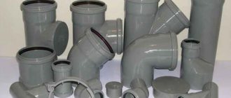
Connection types
For the installation of individual elements of pipeline elements and fittings, fittings and apparatus, special connecting parts are used, selected based on a number of parameters:
- material for the development of pipelines and fittings (the main criterion for their selection is the possibility of welding);
- operating conditions: at low or high pressure, temperature conditions;
- manufacturer's recommendations;
- inclusion of detachable or permanent connecting parts.
How to reduce blood pressure
The problem of high pressure is usually faced by residents of the lower floors of high-rise buildings, where to ensure the required range is 0.3 - 6 atm. at the top you have to supply water with increased pressure from below. Excessive pressure in the circuit leads to accelerated wear of pipeline fittings, inconvenience when using mixing devices and sanitary equipment (increased noise in taps).
The problem in apartment buildings is solved quite simply - in order to reduce the pressure, valves at the entrance to the apartment from the cold water or hot water risers reduce the cross-section of the passage channel.
If sudden changes in pressure are observed in the system, a reducer can be used to reduce or stabilize it. The device has a regulator that allows you to lower the pressure by setting the maximum permissible pressure at the entrance to the apartment (for example, readings of 2 or 3 atm), the threshold value of which cannot be exceeded.
In the autonomous water supply of country houses, the problem of too high a pressure is solved at the installation stage - the adjusting screw on the hydraulic relay is tightened, which lowers the upper threshold of its operation.
Rice. 10 Boost pumps that increase water pressure in the water supply and their use
Linear expansion
The geometric shape of products is changed under force or temperature. Physical stress leading to linear expansion or contraction negatively affects performance. If it is impossible to compensate for expansion, the pipes are deformed, which leads to damage to the flange seals and the areas where the pipes join each other.
When laying out pipelines, you should take into account a possible change in length with an increase in temperature or thermal linear expansion (ΔL). This parameter is determined by the length of the pipes, denoted by Lo, and the temperature difference Δϑ =ϑ2-ϑ1.
In the above formula, the coefficient of thermal linear expansion for a 1 m pipeline with increasing temperature is 1°C.
Correspondence of pipe diameter to carrier volume
Water is used as a coolant in most heating systems. It is heated by a central boiler. Gas, electricity, flammable liquids or solid fuel are used as an energy source. This unit is the heart of the heating system. The heating unit, lines, constipations and heat-emitting radiators form a complex circuit in which each element must be scrupulously verified. Forecasting energy costs and the required boiler power, calculating the heating pipe, choosing the carrier and type of fuel optimize costs during construction and operation. Initial forethought will insure against quick repairs and the need to modify a heating main that has already been put into operation.
Installation of an autonomous heating system
Calculation of pipes for heating a private house can be ordered by professionals, trusting in experience. Plumbing “calculators” help you independently calculate the indicators: programs that calculate heating pipes are offered on the websites of manufacturers and stores. The calculators contain average indicators of typical radiators and pipes: the owner needs to indicate the footage, ceiling height and type of construction, so that the system itself does the calculation of registers from smooth pipes for heating or boiler capacity. The lack of calculators is pre-configuration for the needs of a specific service. It is unlikely that the portal owners will post a program that recommends competitors’ products, even if the calculation of the heating pipe cross-section based on real characteristics provided for this.
Compensators for expansion of pipeline networks
Bends
Special bends welded into the pipeline network compensate for the natural linear expansion of products. This is facilitated by the choice of compensating U-shaped, Z-shaped and corner bends, and linear compensators.
They are designed to accommodate linear expansion of pipes due to deformation, but this technology has a number of limitations. In pipelines with increased pressure levels, elbows at different angles are used to compensate for expansion. The voltage provided in the taps enhances the corrosive effect.
Wavy expansion joints
The products are represented by thin-walled corrugated metal pipes, called bellows, which are stretched in the direction of the pipeline line. They are installed in the pipeline network, the preload serves to compensate for expansion.
The choice of axial expansion joints allows for cross-sectional expansion. Internal guide rings prevent lateral movement and internal contamination. To protect the pipes from external influences, a special lining is used. Expansion joints that do not include an internal guide ring help absorb lateral movement and vibration from pumping systems.
The pressing question is what pipeline diameter to use
The schematic diagram of the steam-condensate path looks like this.
A boiler plant operates, producing steam of a certain parameter in a certain quantity. Next, the main steam valve opens and steam enters the steam-condensate system, moving towards consumers. And here the pressing question arises: what diameter of the pipeline to use? If you take a pipe with a diameter that is too large, it threatens:
- Increased installation costs
- Large heat losses to the environment
- A large amount of condensate, which means a large number of condensate pockets, steam traps, valves, etc.
If you take a pipe of too small a diameter, then this threatens:
- Pressure loss below design
- Increased steam velocity, noise in the steam line
- Erosive wear, more frequent replacement of equipment due to water hammer
Calculation of steam pipeline diameter
There are two methods for choosing the diameter of a steam line: the first is the pressure drop method, and the second is simpler and is used by most of us - the speed method.
In order for you not to waste your time searching for a table for calculating using the speed method, we have posted this information on this page for your convenience. The published recommendations are taken from the catalog of the manufacturer of industrial pipeline fittings ADL.
Insulation protection
For pipelines designed to move high-temperature media, a choice of insulation is provided:
- up to 100°C, use rigid foam (polystyrene or polyurethane);
- up to 600°C, the use of shaped shells or mineral fibers (stone wool or glass felt) is provided;
- up to 1200°C – fibers based on ceramics or alumina.
Pipes with a conditional permeability below DN 80 and an insulating protection thickness of up to 5 s are treated with insulating shaped elements. This is facilitated by 2 shells placed around the pipes and connected using a metal tape, covered with a casing made of tin material.
Pipes with conditional flow from DN 80 are equipped with thermal insulation material with a lower frame. It includes clamping rings, spacers and metal cladding designed from galvanized mild steel material or stainless steel sheet. Insulating material is placed between the pipes and the metal casing.
The thermal insulation layer ranges in size from 5 to 25 cm. It is applied along the entire length of the pipes, on bends and elbows. It is important to exclude the presence of unprotected areas that affect the formation of heat loss. Shaped insulation serves to protect flange connections and fittings. This facilitates unhindered access to the connecting areas without removing the insulation along the entire line if the sealing properties are violated.
The pressing question is what pipeline diameter to use?
The schematic diagram of the steam-condensate path looks like this. A boiler plant operates, producing steam of a certain parameter in a certain quantity. Next, the main steam valve opens and steam enters the steam-condensate system, moving towards consumers. And here the pressing question arises: what diameter of the pipeline to use?
If you take a pipe with a diameter that is too large, it threatens:
- Increased installation costs
- Large heat losses to the environment
- A large amount of condensate, which means a large number of condensate pockets, steam traps, valves, etc.
If you take a pipe of too small a diameter, then this threatens:
- Pressure loss below design
- Increased steam velocity, noise in the steam line
- Erosive wear, more frequent replacement of equipment due to water hammer
Calculation of steam pipeline diameter
There are two methods for choosing the diameter of a steam line: the first is the pressure drop method, and the second is simpler and is used by most of us - the speed method.
In order for you not to waste your time searching for a table for calculating using the speed method, we have posted this information on this page for your convenience. The published recommendations are taken from the catalog of the manufacturer of industrial pipeline fittings ADL.
Reducing pressure and calculating hydraulic resistance
To determine the pressure inside the pipes and correctly select equipment that facilitates the pumping of liquid or gaseous media, it is necessary to calculate the pressure drop. In the absence of access to the Internet, calculations are made according to the formula:
Δp = λ ( l / d 1 ) ( ρ /2) v ²
Δp – voltage drops in the pipeline section, Pa l – length of the pipeline section, m λ – resistance coefficient d1 – pipe cross-section, m ρ – density level of the transported media, kg/m3 v – movement speed, m/s
Hydraulic resistance is formed under the influence of 2 main factors:
- friction resistance;
- local resistance.
The first option is provided for the formation of irregularities and roughness that impede the movement of the pumped media. To overcome the inhibitory effect, additional energy consumption is required. With a laminar flow and a corresponding low Reynolds index (Re), characterized by uniformity and excluding the possibility of mixing adjacent layers of liquid or gaseous media, the influence of roughness is minimal. This is explained by an increase in the parameter of the extreme viscous sublayer of the pumped media, relative to the formed irregularities and protrusions on the surface of the pipes. These conditions allow the pipes to be considered hydraulically smooth.
With an increase in the Reynolds value, the viscous sublayer has a smaller thickness, which ensures the overlap of irregularities and the effects of roughness; the level of hydraulic resistance does not depend on the Reynolds index and the average height of the protrusions on the pipe coating. A subsequent increase in the Reynolds value allows the pumped media to be transferred to a turbulent flow mode, where destruction of the viscous sublayer occurs, and the resulting friction is determined by the magnitude of the roughness.
Friction losses are calculated by substituting the data:
HT=[(λ·l)/de]·[w2/(2g)]
- HT – pressure loss due to friction resistance, m
- [w2/(2g)] – velocity head, m
- λ – resistance coefficient
- l – length of the pipeline section, m
- dE – equivalent value of the cross-section of the pipeline line, m
- w – speed of media movement, m/s
- g – free fall acceleration, m/s2
The fluid flow rate is
where q > design fluid flow, m3/s;
– open cross-sectional area of the pipe, m2.
The friction resistance coefficient λ is determined in accordance with the regulations of the set of rules SP 40-102-2000 “Design and installation of pipelines for water supply and sewerage systems made of polymer materials. General requirements":
where b is a certain number of similarity of fluid flow regimes; for b > 2, b = 2 is accepted.
where Re is the actual Reynolds number.
where ν is the coefficient of kinematic viscosity of the liquid, m²/s. When calculating cold water supply systems, it is assumed to be 1.31 · 10-6 m²/s – the viscosity of water at a temperature of +10 °C;
Req > - Reynolds number corresponding to the beginning of the quadratic region of hydraulic resistance.
where Ke is the hydraulic roughness of the pipe material, m. For pipes made of polymer materials, Ke = 0.00002 m is accepted, unless the pipe manufacturer provides other roughness values.
In those flow cases where Re ≥ Rekv, the calculated value of the parameter b becomes equal to 2, and formula (4) is significantly simplified, turning into the well-known Prandtl formula:
At Ke = 0.00002 m, the quadratic resistance region occurs at a water flow speed (ν = 1.31 · 10-6 m²/s) equal to 32.75 m/s, which is practically unattainable in public water supply systems.
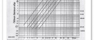
For everyday calculations, nomograms are recommended, and for more accurate calculations - “Tables for hydraulic calculations of pipelines made of polymeric materials”, volume 1 “Pressure pipelines” (A.Ya. Dobromyslov, M., VNIIMP publishing house, 2004).
When calculating using nomograms, the result is achieved by simply applying a ruler - you should connect the point with the value of the design diameter on the dр scale with a straight line to the point with the value of the design flow rate on the q scale (l/s), continue this straight line until it intersects with the speed V and specific loss scales pressure 1000 i (mm/m). The intersection points of a straight line with these scales give the value of V and 1000 i.
As is known, the energy costs for pumping liquid are directly proportional to the value of H (all other things being equal). Substituting expression (3) into formula (2), it is easy to see that the value of i (and, therefore, H) is inversely proportional to the calculated diameter dр to the fifth power.
It is shown above that the value of dр depends on the thickness of the pipe wall e: the thinner the wall, the higher dр and, accordingly, the lower the pressure loss due to friction and energy costs.
If the MRS value of the pipe changes for any reason in the future, its diameter and wall thickness (SDR) must be recalculated.
It should be borne in mind that in a number of cases, the use of pipes with MRS 10 instead of pipes with MRS 8, especially pipes with MRS 6.3, allows one to reduce the diameter of the pipeline by one size. Therefore, in our time, the use of polyethylene PE 80 (MRS and PE 100 (MRS 10) instead of polyethylene PE 63 (MRS 6.3) for the manufacture of pipes allows not only to reduce the thickness of the pipe wall, their weight and material consumption, but also to reduce energy costs for pumping liquids (other things being equal).
In recent years (after 2013), pipes made from PE80 polyethylene have been almost completely replaced from production by pipes made from PE100 grade polyethylene. This is explained by the fact that the raw materials from which the pipes are made are supplied from abroad in the PE100 grade. And also because grade 100 polyethylene has more strength characteristics, due to which pipes are produced with the same characteristics as PE80 pipes, but with a thinner wall, thereby increasing the throughput of polyethylene pipelines.
Nomogram for determining pressure losses in pipes with diameters of 6, 100 mm.
Nomogram for determining pressure losses in pipes with diameters of 100, 1200 mm.
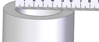
Equivalent diameter value
Used when carrying out calculations of non-cylindrical pipeline systems (oval or rectangular cross-section). The equivalent diameter value corresponds to the parameters of a pipeline network with a circular cross-section, provided the length is the same. To carry out calculations use the formula:
d e = 4 F / P
For pipes with a cylindrical shape, the equivalent and internal cross-sections are the same. For open channels, the equivalent diameter is calculated by substituting the data:
d e = 4 F / P s
The wetted perimeter is the length of the line of interface of the transported media with the walls of the pipeline, which affects the flow restriction. Below are the perimeter shapes for different pipes.
Local resistance is formed by pipeline elements where the transported media are subject to sudden formation of deformations with a change in direction, speed or turbulence. This process can be caused by the action of valves, valves, turns and pipe forks.
Pressure loss due to local friction is calculated using the formula:
Hms=ζms·[w2/(2g)]
The level of pressure loss due to local friction is determined by the speed and coefficient of local resistance (indicated in the tabular data).
When summing up the above formulas, we obtain a general equation that allows us to determine the pump pressure:
What is the water pressure in the water supply of an apartment building?
Government Decree of the Russian Federation dated May 6, 2011 No. 354, which regulates the procedure for providing utility services to citizens living in apartment buildings or using premises there for various purposes, stipulates the maximum and minimum pressure in the hot (DHW) and cold (CW) water supply lines.
The generally accepted pressure of cold water at the water intake point is from 0.03 MPa (0.3 kgf/cm2, atm., bar) to 0.6 MPa (6 kgf/cm2, atm. bar).
For water taps, which can be used by residents in the absence of water supplies, the minimum pressure is set at 0.1 MPa (1 kgf/cm2).
For hot water supply, existing standards at the water point are just below the cold water supply and range from 0.03 MPa (0.3 kgf/cm2) to 0.45 MPa (4.5 kgf/cm2).
The given standards apply to the hours of maximum intake in the morning from 7.00 to 9.00 and in the evening from 19.00 to 22.00, that is, at the time when consumption volumes from the main line are at their highest.
Rice. 4 Consumption standards per resident of apartment-type buildings according to SNiP 2.04.01-85*
Free head
It is clear that the pressure in the internal apartment water supply of high-rise buildings is directly related to its parameters at the inlet; SNiP 2.04.02-84 regulates its values in external water-bearing networks, the main points of the document:
- According to the standards, the pressure in the city water supply of populated areas, taking into account the maximum volumes of consumption for household and drinking needs at the entrance to buildings, is assumed to be at least 10 m (1 atm.). When calculating the required pressure at the entrance of high-rise buildings, 4 m are added to each floor.
- If it is possible to regulate the pressure in the main network at the entrance to the building, then it is permissible to add 3 m of pressure to each floor. In this case, the building should be equipped with reservoirs for storing water reserves.
- If buildings of different heights or built on hills are connected to external water supply networks, it is permissible to install local pumping equipment to increase pressure in high-rise buildings and structures built at heights.
- Since the water taps are connected to external water-bearing networks and are located at the height of the house inlets located at ground level, the minimum pressure in them is taken to be 10 m.
- The maximum input pressure into buildings for water supply networks for household and drinking purposes should not be higher than 60 m.
- If individual buildings or areas are connected to an external water supply network with a pipe pressure of 60 m, regulators are used to compensate for excess pressure or the water supply system is divided into zones.
- In addition to water supply networks for household needs and drinking purposes, low and high pressure fire lines are laid in populated areas.
- For low-pressure fire-fighting pipelines, a pressure of at least 10 m is assumed. If the branches for drinking water and fire-fighting purposes are combined, the maximum pressure level should not be higher than 60 m.
Diameter of pipeline networks
When calculating the cross-section of pipes, it should be taken into account that the high speed of the pumped media reduces the material consumption of products and reduces the cost of installing systems. But an increase in speed leads to pressure losses, requiring additional energy consumption to pump media. Excessive reduction can lead to negative consequences. To calculate the optimal parameters of the cross-section of pipes, use the formula (for products with a round cross-section):
Q = ( Πd² /4) w
To calculate the optimal cross-section parameters, you need to find out the speed of the pumped media based on the summary tables:
The final equation for determining the optimal cross section is:
d = √(4 Q / Πw )
How to increase pressure
In an apartment or cottage-type house, the pressure in the pipeline can be increased in the only way - by installing a special booster pump in the pipeline.
The unit, with its impeller blades, will push water through the pipes at increased speed, thereby creating increased pressure in the line.
In multi-storey apartment buildings, a situation may arise when the use of a booster electric pump in an apartment will lead to pumping out water from the risers of consumers on the upper or lower floors. To avoid complaints from neighbors and possible troubles, one option is to install a storage tank in the apartment. A float switch is installed in it, which has an automatic shut-off valve connected inside to the lever, and the inlet pipe is connected to the water supply. After filling the tank with water, the float rises and shuts off the water supply (the operating principle is similar to the toilet filling system).
Since the storage tank cannot always provide the required pressure in the apartment, a booster pump is additionally installed in the line, which automatically turns on when the pressure in the pipeline is 0.2 or 0.3 bar.
Rice. 11 Measurement of pressure in the apartment
Nomograms for hydraulic pipe calculations
To check pressure losses in a given area, the indicators of pressure gauges are compared with tabular data, or they are guided by the functional dependence of fluid flow on changes in voltage (at a constant diameter).
For example, a branch with 10 kW radiators is used. The fluid flow rate is calculated to transfer heat energy at a level of 10 kW. A section from the first battery in the branch was taken as the calculation section. Its diameter is constant. The second section is located between the 1st and 2nd batteries. In the second section, the energy consumption is 9 kW with a possible reduction.
The hydraulic resistance is calculated up to the return and supply pipes, this is facilitated by the formula:
G uch = (3.6*Q uch)/(c*(t rt o)),
where Q uch is the level of heat load of the area, (W). The heat load for 1 area is 10 kW;
c - (indicator of specific heat capacity for liquid) constant, equal to 4.2 kJ (kg * ° C);
tr is the temperature regime of the hot coolant;
to is the temperature regime of the cold coolant.
Hydraulic calculations of gravity heating systems: coolant transportation speed
The minimum coolant speed is 0.2-0.26 m/s. When the parameter decreases, excess air masses may be released from the liquid, leading to the formation of air pockets. This is the reason for complete or partial abandonment of the heating system. The upper threshold of coolant speed is 0.6-1.5 m/s. Failure to reach the specified speed may result in the formation of hydraulic noise. In practice, the optimal speed varies in the range of 0.4-0.7 m/s.
For more accurate calculations, the parameters of the materials for making pipes are used. For example, for steel pipes, the fluid speed varies in the range of 0.26-0.5 m/s. When using polymer or copper products, it is allowed to increase the speed to 0.26-0.7 m/s.
Calculation of resistance of gravity heating systems: pressure loss
The sum of all losses due to hydraulic friction and local resistance is determined in Pa:
Handle = R * l + ((p * v2) / 2) * E3,
- where v is the speed of transported media m/s;
- p—liquid density, kg/m³;
- R—pressure loss, Pa/m;
- l is the length used for pipe calculations, m;
- E3 is the sum of all local resistance coefficients in the equipped area of the shut-off valves.
The overall level of hydraulic resistance is determined by the sum of the resistances of the design sections.
Hydrocalculation of two-pipe gravity heating systems: selection of the main branch
If the hydraulic system is characterized by associated transportation of the coolant, for two-pipe systems you should select a ring of the maximum loaded riser through the heating devices located below. For systems characterized by dead-end coolant movement, it is necessary to select a ring of the lower heating device for the most loaded of the most remote risers. For horizontal heating structures, rings are selected through the busiest branches belonging to the lower floors.
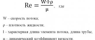
Reynolds criterion
This dependence was derived by the English physicist and engineer Osborne Reynolds (1842 - 1912).
A criterion that helps answer the question of whether it is necessary to take into account viscosity is the Reynolds number Re. It is equal to the ratio of the energy of motion of an element of a flowing fluid to the work of internal friction forces.
Consider a cubic fluid element with edge length n. The kinetic energy of the element is:
According to Newton's law, the friction force acting on a fluid element is determined as follows:
The work done by this force when moving a fluid element a distance n is
and the ratio of the kinetic energy of a fluid element to the work done by the friction force is equal to
We reduce and get:
Re is called the Reynolds number.
Thus, Re is a dimensionless quantity that characterizes the relative role of viscous forces.
For example, if the dimensions of the body with which the liquid or gas comes into contact are very small, then even with low viscosity Re will be insignificant and friction forces play a predominant role. On the contrary, if the size of the body and the speed are large, then Re >> 1 and even high viscosity will have almost no effect on the nature of the movement.
However, large Reynolds numbers do not always mean that viscosity does not play any role. Thus, when a very large (several tens or hundreds of thousands) value of the Re number is reached, a smooth laminar (from the Latin lamina - “plate”) flow turns into a turbulent (from the Latin turbulentus - “stormy”, “chaotic”), accompanied by chaotic, unsteady movements liquids. This effect can be observed if you gradually open a water tap: a thin stream usually flows smoothly, but as the speed of the water increases, the smoothness of the flow is disrupted. In a stream flowing out under high pressure, liquid particles move randomly, oscillating, and all movement is accompanied by strong mixing.
The appearance of turbulence significantly increases drag. In a pipeline, the speed of turbulent flow is less than the speed of laminar flow at the same pressure drops. But turbulence is not always bad. Due to the fact that mixing during turbulence is very significant, heat exchange - cooling or heating of aggregates - occurs much more intensely; Chemical reactions spread faster.
Examples of nomograms
When choosing the parameters of pipes and materials for development, specialists are guided by the technological and design requirements imposed in a particular situation. To standardize dimensions, they are classified and unified, taking into account the pressure permissible for operation.
Modern means
If you don’t have time or are not inclined to mathematics, you can calculate the water flow through the pipeline taking into account the pressure drop using an online calculator. The Internet is replete with sites with tools. To make a hydraulic calculation, it is necessary to take into account the loss coefficient. This approach involves choosing:
- pressure drop per linear meter of pipeline;
- length of the section;
- internal diameter of the pipe;
- type and material of the plumbing system (plastic, reinforced concrete, asbestos cement, cast iron, steel). Modern online calculators even take into account, for example, the lower roughness of a plastic surface compared to a steel one;
- method for calculating resistance.
In addition, the user has access to options for taking into account additional characteristics of pipelines, in particular, such as the type of coating. For example:
- cement-sand, applied by various methods;
- external polymer cement or plastic;
- new or serviced pipelines for a certain period of time with a bitumen coating or without a protective internal coating.
If the calculation is done correctly, provided that the installation is carried out in compliance with all requirements for the water supply system, there will be no complaints.