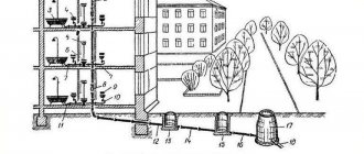
In order to correctly install the water supply structure, when starting to develop and plan the system, it is necessary to calculate the water flow through the pipe.
The basic parameters of the home water supply system depend on the data obtained.
In this article, readers will be able to get acquainted with the basic techniques that will help them independently calculate their plumbing system.
How to calculate the required pipe diameter
The purpose of calculating the diameter of a pipeline by flow rate: Determination of the diameter and cross-section of the pipeline based on data on flow rate and the speed of longitudinal movement of water.
It is quite difficult to perform such a calculation. It is necessary to take into account a lot of nuances related to technical and economic data. These parameters are interconnected. The diameter of the pipeline depends on the type of liquid that will be pumped through it.
If you increase the flow speed, you can reduce the diameter of the pipe. Material consumption will automatically decrease. It will be much easier to install such a system, and the cost of work will fall.
However, an increase in flow movement will cause pressure losses, which require the creation of additional energy for pumping. If you reduce it too much, undesirable consequences may appear.
Using the formulas below, you can both calculate the water flow in the pipe and determine the dependence of the pipe diameter on the liquid flow.
When designing a pipeline, in most cases, the water flow rate is immediately specified. Two quantities remain unknown:
- Pipe diameter;
- Flow rate.
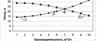
It is very difficult to make a complete technical and economic calculation. This requires appropriate engineering knowledge and a lot of time. To make this task easier when calculating the required pipe diameter, use reference materials. They give the values of the best flow rate obtained experimentally.
The final calculation formula for the optimal pipeline diameter is as follows:
d = √(4Q/Πw) Q – flow rate of the pumped liquid, m3/s d – pipeline diameter, m w – flow velocity, m/s
Calculation methods
The friction coefficient is affected by the presence of locking elements and their number.
To determine the permeability of the water supply system, you can use three calculation methods:
- Physical method. Formulas are used to determine the indicators. Calculation requires knowledge of several parameters, in particular, the cross-sectional size of the pipe section and at what speed the water moves in the main.
- Table method. It is the simplest, since by selecting the indicators in the table, you can immediately find out the necessary data.
Water supply calculation program - Computer programming. Such “software” can be easily found and downloaded on the Internet. It was created specifically to determine the patency of pipes of any system. To find out the required parameter, you need to enter the starting data into the program: material, length, quality of the coolant.
The last method, although the most accurate, is not suitable for calculating ordinary household communications. It is quite complex, and to use it you will need to know a variety of indicators. To calculate a simple network for a private home, you should use an online calculator. Although it is not as accurate, it is free and does not need to be installed on your computer. You can achieve more accurate information by checking the data calculated by the program with the table.
Suitable fluid speed, depending on the type of pipeline
First of all, the minimum costs are taken into account, without which it is impossible to pump the liquid. In addition, the cost of the pipeline must be considered.
When making calculations, you must always remember the speed limitations of the moving medium. In some cases, the size of the main pipeline must meet the requirements laid down in the technological process.
The dimensions of the pipeline are also affected by possible pressure surges.
When preliminary calculations are made, pressure changes are not taken into account. The design of a process pipeline is based on the permissible speed.
When there are changes in the direction of movement in the designed pipeline, the surface of the pipe begins to experience high pressure directed perpendicular to the flow movement.
This increase is associated with several indicators:
- Fluid velocity;
- Density;
- Initial pressure (pressure).
Moreover, the speed is always in inverse proportion to the diameter of the pipe. That is why high-speed liquids require the correct choice of configuration and proper selection of pipeline dimensions.
For example, if sulfuric acid is pumped, the speed is limited to a value that will not cause erosion on the walls of the pipe bends. As a result, the structure of the pipe will never be damaged.
Devices for converting delta “P” into a flow signal
The three most common devices are pressure gauges, diaphragms, and bellows. Using a pressure gauge, you can take a reading of the pressure drop directly from the device. Membranes and bellows can be connected to instrumentation.
Diagram with pressure gauge
A pressure gauge is one of the most common instruments used to control and measure pressure drop. In the diagram shown, a pressure gauge measures the pressure difference created by a diaphragm. One end of the pressure gauge is connected to a high side tap located upstream of the diaphragm. The other end of the pressure gauge is connected to a low side tap located downstream of the diaphragm. As a flow of liquid, gas or steam passes through the diaphragm, the pressure gauge senses the difference in pressure created by the diaphragm and indicates this difference by the height of the liquid in the tube. The pressure gauge scale allows you to take the reading of this measured delta “P” virtually directly from the device.
Protection of the pressure gauge from liquid, gas or vapor from the pipeline is usually carried out in measuring systems using insulating membranes or using some other means.
Diagram with membrane
The figure above shows a diagram in which the membrane acts as a device for determining delta “P”. In this diagram, the membrane is placed in a chamber that has entrances on both sides. One input is connected to the high side tap and the other input is connected to the low side tap. The indicator arm is fixed at the top of the chamber, and its lower end is attached to the membrane. The pressure difference inside the chamber sets the membrane in motion, which, in turn, sets the needle in motion, causing it to deviate in one direction or the other. As the differential pressure increases or decreases, the mechanical movement of the diaphragm is transmitted to the indicator lever.
Scheme with two bellows
This is a circuit in which two corrugated bellows are used to convert the delta “P” value into mechanical movement. Parts of the diagram shown include: two bellows connected together with a partition between them, a lever, an indicator needle and a scale.
The bellows labeled "A" is connected to the high side bleed, and the bellows labeled "B" is connected to the low side bleed. The bellows are placed in the chamber. The partition between the bellows can move freely. Using a lever mounted on the partition, the mechanical movement of the bellows is transmitted to the indicator needle, which can move along the scale.
Density and Specific Gravity
The most important characteristics of the mechanical properties of a liquid are its density and specific gravity. They determine the “gravity” of the liquid.
Density ρ (kg/m 3 ) is understood as the mass of liquid m contained in a unit of its volume V, i.e.
Instead of density, specific gravity γ (N/m3) can also be used in the formulas, i.e. weight G = m⋅g per unit volume V:
γ = G / V = m⋅g / V = ρ⋅g
Changes in the density and specific gravity of a liquid with changes in temperature and pressure are insignificant, and in most cases they are not taken into account.
Densities of the most commonly used liquids and gases (kg/m3):
| petrol | 710. 780 |
| kerosene | 790. 860 |
| water | 1000 |
| mercury | 13600 |
| hydraulic system oil (AMG-10) | 850 |
| spindle oil | 890. 900 |
| industrial oil | 880. 920 |
| turbine oil | 900 |
| methane | 0,7 |
| air | 1,3 |
| carbon dioxide | 2,0 |
| propane | 2,0 |
Recommended comfortable pressure
It is not convenient to use water from taps and mixers with high or low pressure in the water supply. For comfortable use of water from faucets and showers, it is recommended that the pressure in the water supply system be from 1.0 to 2.0 kgf/cm2. However, some types of household equipment require higher pressure. In this case, you should focus on the minimum for such equipment.
If water is used to water the area of a private house or country house, you can increase the pressure in the water supply to 3 kgf/cm2 to reduce watering time and compensate for the loss of pressure in a thin long hose.
Compressibility
Compressibility is the ability of a liquid to change its volume under the influence of pressure. The compressibility of droplet liquids and gases differs significantly. Thus, droplet liquids change their volume extremely slightly when pressure changes. Gases, on the contrary, can be significantly compressed under pressure and expand indefinitely in the absence of pressure.
To take into account the compressibility of gases under various conditions, equations of gas state or dependencies for polytropic processes can be used.
The compressibility of droplet liquids is characterized by the volumetric compression coefficient βр (Pa -1):
| βр = | dV | · | 1 |
| dp | V |
where dV is the change in volume under pressure; dр—pressure change; V is the volume of liquid.
The minus sign in the formula is due to the fact that as the pressure increases, the volume of the liquid decreases, i.e. a positive increase in pressure causes a negative increase in volume.
Types of pipeline pressures
Any user who independently deals with water supply often encounters various terms that determine the pressure in the water supply system, the main ones (according to GOST 356-80 (ST SEV 253-76):
Nominal PN. When purchasing pipes for water supply installation on the construction market, you are often faced with an indication of their service life; for products made from different materials it is different and ranges from 20 years for steel and 50 years for polymers.
The user should be aware that the PN indicator means that the pipe at a given maximum excess pressure can operate for the specified operational period under the only condition - the temperature of the working environment should not exceed a threshold of + 20 ° C.
Working Rr. It is known that as the temperature of the transported medium increases, the service life of any pipelines decreases. In the heating circuit, the coolant temperature usually does not go beyond the range of 50 - 70 °C for radiators and 35 - 50 °C for heated floors, that is, the nominal PN for these pipes is not relevant.
Therefore, for pipelines, the operating pressure in the water supply system is additionally set equal to the highest excess pressure at which the pipe can operate for its allotted service life in a given operating mode. Usually Рр is calculated when supplying a working medium of a certain temperature (usually above + 20 °C) or its physico-chemical characteristics different from neutral water.
Trial Rpr. Indicates the excess standard pressure, which is established during hydraulic tests of pipelines and fittings for the strength and tightness of connections in a standardized temperature range from + 5 to + 70 ° C.
Rice. 9 Gearbox and its design
Related article:
Water pressure regulator in the water supply system - types and designs, installation . In a separate article we talk in detail about special pressure regulators that are installed in the water supply system, thus normalizing the water pressure. Read it, it might be interesting.
Temperature expansion
The ability of a liquid to change its volume with changes in temperature is called thermal expansion. It is characterized by the coefficient of thermal expansion βt:
| βt = | dV | · | 1 |
| dT | V |
where dT is temperature change; dV - change in volume under the influence of temperature; V is the volume of liquid.
At finite temperature increments:
| ρ1 = | ρ |
| 1 + βt·ΔT |
As can be seen from the formulas, with increasing temperature the volume of the liquid increases and the density decreases.
The coefficient of thermal expansion of liquids depends on pressure and temperature:
| T, °C | p, MPa | βt, 1/deg |
| 0,1 | 14·10 -6 | |
| 100 | 10 | 700·10 -6 |
That is, under different conditions, the coefficient of thermal expansion changed 50 times. However, in practice, the average value in a given temperature and pressure range is usually taken. For example, for mineral oils βt ≈ 800·10 -6 1/deg.
Gases change their volume quite significantly with temperature changes. To take this change into account, equations of state of gases or formulas of polytropic processes are used.