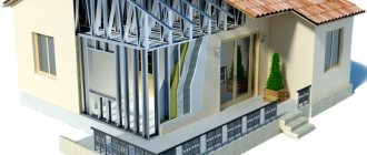
A beam is an element of building load-bearing structures that is widely used for the construction of interfloor floors. Floors, in turn, are designed to separate adjacent rooms by height, as well as to accept static and dynamic loads from interior items, equipment, people, etc. located on it.
In most cases, for private housing construction, wooden beams made of solid timber, hewn logs, laminated boards or veneer are used. These materials, with the correct selection of parameters, can provide the necessary strength and rigidity of the base, which is the key to the durability of the building.
We suggest you perform an online calculation of the floor beam for strength and bending , select its cross-section and determine the spacing between the beams. You will also receive a set of personal drawings and a 3D model for a better perception of the structure being built. The program takes into account SNiP II-25-80 (SP 64.13330.2011) and other reference sources.
Accurate and competent calculation of wooden beams in the KALK.PRO allows you to find out all the necessary parameters for the construction of a strong floor. All calculations are free, it is possible to save the calculated data in PDF format, plus diagrams and a 3D model are available.
- Beam length
- Determination of design load
- Maximum bending moment
- Required moment of resistance
- Moment of resistance of the floor beam
- Calculation of beam strength
- Calculation of beams for deflection (bending)
- Final beam parameters
Instructions for the calculator
Our service provides a choice of two types of calculations for single-span floor beams. In the first case, you are asked to calculate the section of the beam with a known step between them, in the second case, you can find out the recommended value of the step between the beams with the selected section characteristics. Let's look at how the calculator works using an example when your task is to find the cross-section of a beam.
To calculate, you will need to know a number of required initial parameters. First of all, these are the characteristics of the beam itself:
- section width (thickness), mm;
- beam span length (BLN in the image), m;
- type of wood (pine, spruce, larch...);
- wood class (1/K26, 2/K24, 3/K16);
- impregnation (yes, no).
If you do not know the thickness of the proposed beam , in the first block you should select the item “The ratio of the height of the section of the beam to its width is known - h/b” and specify the value 1.4. This is the most optimal value, which was obtained empirically and is indicated in many reference books.
Then you need to indicate the conditions under which the ceiling will be used:
- temperature conditions (< 35 °C .. > 50 °C);
- humidity conditions;
- there are constant increased loads or not.
After this, configure the design and fill in the fields of the calculator:
- length of the house wall on the inside, m;
- pitch between beams, cm;
- total length of the beam (BFL in the image), m;
- load on the beam, kg/m2;
- maximum deflection in fractions of the span.
If necessary, enter the cost of one cubic meter of wood in order to find out the total cost of all lumber.
Also, please note that usually the beam pitch is not made less than 0.3 m, since this is not practical from an economic point of view, and more than 1.2 m, since the subfloor may sag with all the ensuing consequences.
When you click the “ Calculate ” button, the service will calculate the beam online and display the recommended cross-section values for the selected beam.
In addition, in the “Calculation Results” block you can find out:
- beam parameters when calculating strength;
- beam parameters when calculating deflection;
- maximum beam deflection, see
A qualified calculation of the floor using wooden beams is the key to the durability of the structure and safety for your family.
What is stronger: a corner or a profile pipe: we delve into the nuances
As in the topic of contrasting a similar pipe with a channel, which we described separately, 2 specific products should be compared, and not both categories as a whole.
The strength of the product depends on the parameters:
- chemical composition of the metal used in production;
- manufacturing method (it was mentioned above that a hot-rolled angle is stronger than a cold-drawn one);
- geometric parameters of the product in question - length, thickness, width;
- weight;
- the presence of a weld (if we are talking about pipes);
- additional surface treatment (galvanization strengthens the product, preventing corrosion from destroying the metal in the long term).
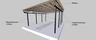
Calculation of floor beams
Independent calculation of a wooden floor beam is a long and tedious task that requires you to know the basics of engineering disciplines and strength of materials. Without certain skills and knowledge, manually selecting the material, calculating the required section or pitch of the beam is not only difficult, but sometimes impossible. However, we will try to tell you about the main characteristics that are needed for calculations and what algorithm our calculator uses.
Types of beams
Currently, wooden beams used for the manufacture of floors can be divided into two fundamentally different types:
- solid;
- glued
Based on the name, it becomes clear that in the first case, it will be a solid piece of wood of a certain type of section (most often it is a beam with 2 or 4 edges), in the second case, it will be a laminated beam made of boards or LVL veneer.
Despite the low cost, for a number of objective reasons, wooden beams made of solid wood have recently been used less and less . The quality characteristics of this material are significantly inferior to laminated wood: the low modulus of elasticity contributes to the appearance of large deflections in the middle of the span (this becomes especially noticeable when the distance between the load-bearing walls is more than 4 meters), when drying, longitudinal cracks appear on the beams, which lead to a decrease in the moment of inertia of the deflection, Lack of impregnation exposes the wood to pests and rot.
Thanks to modern technologies, glued beams do not have such disadvantages . Their structure is homogeneous and the fibers are oriented in all directions - the overall strength and elastic modulus of the material increases, it receives protection from cracking, and special impregnation provides an increased level of fire safety and moisture resistance. These beams are allowed to be used for openings of 6-9 m and can be considered as a full-fledged analogue of an iron floor.
Solid wood beam
Glued beam from boards
Glued veneer beam
Cut log
Selection of beam section
In order to select the section of a beam yourself manually, you need to have a huge amount of knowledge in the field of strength materials, because you will need to apply in practice a large number of formulas and coefficients, so for a novice master this is a rather difficult and not entirely irrational task. Our calculator should help you make an approximate calculation of a wooden floor and save a significant amount of time. However, the user must understand that no program can replace a real specialist, since the operating principle of the service is based on processing standard tabular values and cannot take into account specific situations.
Calculating wooden floor beams is much easier using our calculator. You don't need to keep a lot of formulas in your head and worry about unproduced errors!
Basics of strength of strength
By and large, the basics of the theory of strength of materials (strength of materials) are even simpler than the multiplication table. The multiplication table is large, it needs to be stupidly memorized as “Our Father,” and the basics of strength of strength are reduced to several basic provisions, which are quite easy to visually demonstrate and therefore easy to remember.
However, this is my subjective opinion. Many people believe that the strength of proof is very difficult, there is even a saying: “if you pass the strength of proof, you can get married.” It is easier for humanists and doctors to study a dozen weighty volumes before a session, and for people with an analytical mindset it is easier to remember several basic principles of a particular discipline and it is not even necessary to remember all the formulas. Most of the formulas can be derived by yourself, using the mathematical apparatus and relying on the basic principles, at least that’s what I did during the exams.
Circumstances were such that I missed the introductory course of lectures on strength strength materials, since I returned to the institute after serving in the navy 2 weeks before the session, so I had to learn the basics of strength strength materials myself, for which the most severe and incorruptible teacher on the stream, who failed more than one hundred students , gave me a five. Well, off we go, the teachers, seeing an “A” on the strength of materials test, did not dare to give a lower grade in their subject, and in the end I received a diploma with honors. However, let's not get distracted, but let's get back to the basics.
Beam Calculation - Example
The program algorithm for calculating beams is based on SP 64.13330.2011 (Updated edition of SNiP II-25-80). For greater clarity, we will analyze the calculation of a single-span beam for deflection and strength in an example, briefly describing the main stages of calculation and formulas.
Beam length
The estimated length of the beam is determined by the span length and the margin for laying them on the wall.
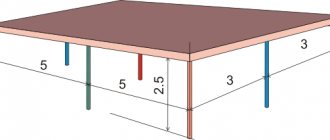
Finding out the length between spans is not difficult - use a tape measure to measure the distance that needs to be covered with beams, and to the resulting number add the amount of embedding in the “sockets” equal to 300 mm (150 mm per side) or more.
In the case when you are going to attach the beams to special metal fasteners, the span length will be equal to the length of the beam.
If your room has an irregular shape, for example, 4x5 m, it would be more correct to use beams of shorter length, i.e. 4 m, not 5 m.
Determination of design load
In order to correctly calculate the load on a wooden beam, you need to determine all types of influences on the floor.
The magnitude of the load can be found out in two ways: use SNiP 2.01.07-85 * Loads and impacts and use it to calculate all the necessary coefficients manually and then add them, or you can take regulatory data from reference books. If you make all the calculations correctly, then the first option will be more accurate, but no one is safe that a mistake will be made when performing long, cumbersome calculations.
Therefore, to obtain an approximate calculation, it is more advisable to take standard values and apply them in subsequent formulas. According to reference books, for interfloor ceilings the design load is usually 400 kg/m2, and for attics - 200 kg/m2.
Typical loads for interfloor ceilings - 400 kg/m2 and attics - 200 kg/m2 are not applicable in all situations . If it is expected that the base will be subject to an abnormally large weight, for example from heavy equipment, it is necessary to adjust the initial parameters.
Maximum bending moment
Bending moment is the moment of external forces relative to the neutral axis of the section of a beam or other solid body, in other words, in simple words, it is the product of force by the arm.
The maximum bending moment, accordingly, takes the greatest value that a given body can withstand without violating its integrity.
If a uniformly distributed load acts on the beam (this is the case implemented in the calculator), then the value of the maximum bending moment will be equal to:
Bending moment (formula): Mmax = q × l2 / 8
- q is the magnitude of the load on the floor;
- l is the size of the floor span.
Required moment of resistance
The moment of resistance is the ability of a material to resist bending, tension or compression. In order to determine this value for a wooden beam, you need to use the ready-made formula:
Required moment of resistance (formula): Wreq = Mmax / R
- Mmax – the value of the maximum bending moment;
- R is the value of the design resistance of wood.
Separately, we need to talk about the value of R. It has a number of correction factors that need to be taken into account when calculating the beam if you want to get the most accurate result. The full formula looks like this:
Design resistance of wood (formula): R = Ri × mп × mд × mт × ma × γсc × …
- Ri is the calculated bending resistance of wood, selected depending on the calculated values for pine, spruce and larch at a humidity of 12% according to SP 64.13330.2011;
- mp – transition coefficient for other types of wood;
- mд – correction factor adopted in the case when permanent and temporary long-term loads exceed 80% of the total voltage of all loads;
- mt – temperature coefficient;
- ma – coefficient adopted in the case when the tree is impregnated with fire retardants;
- γсc – wood service life coefficient.
- ... - there are other less important coefficients, but they are practically not used in calculations, since the magnitude of the correction is too insignificant.
It turns out that, in essence, the value of R is the product of the calculated bending resistance of wood and various corrections. In most cases, to obtain an approximate result, these corrections are not taken into account, and the value of R is taken equal to Ri.
Moment of resistance of the floor beam
Depending on the cross-sectional shape of the beam (square, rectangle, circle, oval...), the formulas for finding the actual moment of resistance will differ . Our calculators use only two types of profile: rectangular and hewn log. We will continue to analyze the algorithm using the example of a rectangular section:
Moment of resistance of the beam (formula): W = b × h2 /6
- b – beam width;
- h – beam height.
Comparing channel and profile pipe
Channel is a more “serious” profile. You are unlikely to see home furniture with a metal frame made of channel steel - for this they use corrugated pipe. And vice versa, in the load-bearing parts of the metal frame of massive buildings (shopping centers, hangars, exhibition complexes) the channel is found everywhere, the corrugated pipe is extremely rare. This happens due to the fact that the frame consists of elements that complement each other and carry a common load. In this case, a channel is more suitable: this rolled material can withstand loads well due to its profile and thicker walls. But the channel is not universal due to its profile. Therefore, small products “for oneself”, where there is no need to consider the load and a sufficient safety margin of a profile pipe, where the versatility of rolling is needed (the same piece of pipe can be used anywhere in the frame) is preferred to be made from pipe.
When asked which is better (stronger, stronger, stiffer): a channel or a profile pipe, we answer: you need to compare in practice. Rolled metal elements are good in each case. That is, in the conditions of production of frames for home furniture, a corrugated pipe is better, and in conditions of production of frames for massive buildings, a channel is better.
A durable and reliable steel corner can be used not only in professional construction, but also in private construction. The variety of its shapes and types makes you think about what properties of a metal corner you need to pay attention to, how all these types differ and how to choose the product that will be optimally suited to your needs, but at the same time not overpay for those properties that are not suitable for your construction needed.
Manufacturing
Metal corners come in two types according to the production method, each of which is regulated by its own GOST and has different properties. Experts can distinguish them even by their appearance.
Hot-rolled steel angle is made from a heated ingot of metal, so its outer corner is sharp, because the product is made according to the shape. It can withstand loads better and is more durable.
A cold-rolled metal corner is obtained by bending a steel strip on a bending machine. There is no scale on it, and the outer corner is rounded due to the bend. It is much less durable than a hot-rolled product, but it is extremely simple to make - you just need to bend the strip, so the variety of its sizes is much wider than that of the strictly regulated hot-rolled version. If you need a non-standard size, then a cold-rolled corner is at your service.
Accuracy
This parameter indicates how large the possible deviations from the ideal drawing are. The greater the deviation, the more uneven or slightly crooked the corner will be. However, even with standard accuracy it is usually enough to create an even structure; as a rule, increased accuracy is needed only for very small corners and certain specific high-precision structures.
You can distinguish accuracy by markings. The standard accuracy marking has the letter B, and the increased accuracy has the letter A.
Steel alloy
Like most metal products, steel profiles can be made from high-alloy, low-alloy or regular carbon steel. Low-alloy steel is the easiest to weld, high-alloy steel has increased strength, and regular steel is universal and the most inexpensive.
Shelves
The shelves of this product can be equal and nervous. In the first case, the metal strip seems to be bent exactly in the middle, and both sides diverging from the top are the same length. This is a very durable option, since such a stiffener best withstands loads.
However, in certain types of construction you need rolled steel, which in cross-section resembles the letter L - one side (shelf) is longer than the other. This type of rolled steel is slightly less durable, but it can be useful for certain structures. It is also used for additional reinforcement.
Calculation of beam strength
In order to determine whether a beam is suitable for strength or not, it is necessary that the moment of resistance of the floor beam (W) is equal to or greater than the required moment (Wreq):
Wreq ≤ W
But we cannot calculate the real moment of resistance of the floor beam, since its height is not known. In this case, you need to either use an enumeration of sections, based on the condition that the most optimal height to width ratio is 1.4:1, or simply accept W = Wrequired, due to the fact that we do not violate the conditions of the given formula. Also, after these manipulations, the parameter h will become known.
The KALK.PRO online calculator for calculating beam strength will quickly calculate the required section so that the floor can withstand the design load FAST and FREE.
Angle and profile pipes: definition, parameters, advantages
It’s easier to answer which corner or profile pipe is stronger when you know more about each type of product. Let's look at the main characteristics:
- Angles are rolled products with an L-shaped diameter. Produced by bending a steel sheet or by thermoforming. The second option is more durable. Products can have shelves of equal or different lengths. The length of products can be measured, unmeasured, multiple of measured, limited unmeasured. There are 2 classes of rolling accuracy - high (A), normal (B).
- Profile rolled products - pipes with diameters in the shape of a square, rectangle, oval, etc. They can be cold-drawn, electric-welded, hot-rolled, with or without seams. Lengths - unmeasured, measured, multiple. The maximum length is within 11.5-12.5 m. Wall thickness varies.
In the question of what is stronger than a profile pipe or an angle, at first glance it seems that rolled pipe is in the lead (due to 4 walls instead of 2, like an angle). But it's not that simple.
Calculation of beams for deflection (bending)
The method for determining beam deflection is much simpler. With a distributed load, the formula applies:
Beam deflection (formula): f = (5 × q × l4) / (384 × E × I)
- q is the magnitude of the load on the floor;
- l is the size of the floor span;
- E – elastic modulus;
- I – moment of inertia.
We know the first two parameters; the modulus of elasticity for wood is usually taken to be 100,000 kgf/m², although this is not always the case, and the moment of inertia, depending on the shape of the section, is calculated using different formulas. For a rectangle:
Moment of inertia (formula): I = b × h3 /12
- b – beam width;
- h – beam height.
Putting everything together, we get the final formula for calculating the deflection of a beam:
Beam deflection (final formula): f = (5 × q × l4) / (384 × E × (b × h3 / 12))
After you receive the desired value, you need to compare it with the value of the permissible (maximum) deflection of the beam in fractions of the span. This parameter is set by SNiP II-25-80 “Wooden structures”:
| Structural elements | Maximum beam deflection, no more |
| 1. Beams between floors | L/250 |
| 2. Attic floor beams | L/200 |
| 3. Floors with screed/plaster | L/350 |
For example, for interfloor ceilings with a span length of 400 cm, we get the condition - 400/250, i.e. the maximum possible bend in this situation is 1.6 cm.
If your f value exceeds it, you need to change the beam section upward until it becomes less than the maximum deflection.
Our wooden beam deflection calculator will automatically select the necessary section parameters and save you from complex cumbersome calculations.
Final beam parameters
After you select the section when calculating strength and deflection/bending, you can determine the minimum permissible parameters of the beam.
Let's assume that when calculating strength you received a cross-section of 165x150 mm, and when calculating deflection - 239x150 mm. Obviously, in such a situation, you should choose the largest value , that is, the deflection value, because if you do exactly the opposite, the ceiling will withstand the load, but will be very deformed and there can be no question of any even ceiling.
As a result of calculating the load-bearing capacity of a wooden beam, we use a section equal to 239x150 mm, but here we are faced with another problem - no one produces beams of this size in series. In this case, it is necessary to round up, usually in multiples of 50 mm, i.e. A beam of 250x150 mm is suitable for us. In some situations, you can refer to GOST 24454-06, which lists all standard sizes of materials.
Calculating beams online without knowing the strength of materials is one of the main advantages of the KALK.PRO service.
Coefficients φ of longitudinal bending of centrally compressed steel elements
| Element flexibility | Values of φ at Ry, MPa | |||||
| 200 | 240 | 280 | 320 | 360 | 400 | |
| 10 | 0,988 | 0,987 | 0,985 | 0,984 | 0,983 | 0,982 |
| 20 | 0,967 | 0,962 | 0,959 | 0,955 | 0,952 | 0,949 |
| 30 | 0,939 | 0,931 | 0,924 | 0,917 | 0,911 | 0,905 |
| 40 | 0.906 | 0,894 | 0,883 | 0,873 | 0,863 | 0,854 |
| 50 | 0,869 | 0,852 | 0,836 | 0,822 | 0,809 | 0,796 |
| 60 | 0,827 | 0,805 | 0,785 | 0,766 | 0,749 | 0,721 |
| 70 | 0,782 | 0,754 | 0,724 | 0,687 | 0,654 | 0,623 |
| 80 | 0,734 | 0,686 | 0,641 | 0,602 | 0,566 | 0,532 |
| 90 | 0,665 | 0,612 | 0,565 | 0,522 | 0,483 | 0,447 |
| 100 | 0,599 | 0,542 | 0,493 | 0,448 | 0,408 | 0,369 |
| 110 | 0,537 | 0,478 | 0,427 | 0,381 | 0,338 | 0,306 |
| 120 | 0,479 | 0,419 | 0,366 | 0,321 | 0,287 | 0,260 |
| 130 | 0,425 | 0,364 | 0,313 | 0,276 | 0,247 | 0,223 |
| 140 | 0,376 | 0,315 | 0,272 | 0,240 | 0,215 | 0,195 |
| 150 | 0,328 | 0,276 | 0,239 | 0,211 | 0,189 | 0,171 |
| 160 | 0,290 | 0,244 | 0,212 | 0,187 | 0,167 | 0,152 |
| 170 | 0,259 | 0,218 | 0,189 | 0,167 | 0,150 | 0,136 |
| 180 | 0,233 | 0,196 | 0,170 | 0,150 | 0,135 | 0,123 |
| 190 | 0,210 | 0,177 | 0,154 | 0,136 | 0,122 | 0,111 |
| 200 | 0,191 | 0,161 | 0,140 | 0,124 | 0,111 | 0,101 |
| 210 | 0,174 | 0,147 | 0,128 | 0,113 | 0,102 | 0,093 |
| 220 | 0,160 | 0,135 | 0,118 | 0,104 | 0,094 | 0,086 |
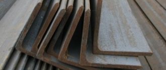
Assortment of hot rolled angles
The high strength of these products ensures their use in creating structures that operate under severe loads. The range of equal flange hot-rolled angles is regulated by GOST 8509-93. The standard provides for two classes of rolling accuracy:
- A - increased;
- B - ordinary.
In the production of angle steel, carbon steel of ordinary quality and high-quality structural steel are used. For the manufacture of critical structures and elements of machines and mechanisms, angles made of low-alloy steels of type 09G2S, 10HSND are used. Such products can be used in a wide temperature range (-70...+450°C), therefore they are in demand in regions with harsh climates.
Table of dimensions and weight of the most common range of steel equal-flange angles according to GOST 8509-93
| Shelf width, mm | Shelf thickness, mm | Weight of 1 meter, kg | Shelf width, mm | Shelf thickness, mm | Weight of 1 meter, kg |
| 20 | 3 | 0,89 | 63 | 4 | 3,9 |
| 4 | 1,15 | 5 | 4,81 | ||
| 25 | 3 | 1,12 | 6 | 5,72 | |
| 4 | 1,46 | 70 | 5 | 5,38 | |
| 30 | 3 | 1,36 | 6 | 6,39 | |
| 4 | 1,78 | 7 | 7,39 | ||
| 35 | 3 | 1,6 | 75 | 5 | 5,8 |
| 4 | 2,1 | 6 | 6,89 | ||
| 5 | 2,58 | 7 | 7,96 | ||
| 40 | 3 | 1,85 | 8 | 9,02 | |
| 4 | 2,42 | 80 | 6 | 7,36 | |
| 5 | 2,98 | 7 | 8,51 | ||
| 45 | 3 | 2,08 | 8 | 9,65 | |
| 4 | 2,73 | 90 | 7 | 9,64 | |
| 5 | 3,37 | 8 | 10,93 | ||
| 50 | 3 | 2,32 | 9 | 12,2 | |
| 4 | 3,05 | 100 | 7 | 10,79 | |
| 5 | 3,77 | 8 | 12,25 | ||
| 6 | 4,47 | 10 | 15,1 |
What is stronger: corner or profile pipe?
Good afternoon, dear forum users! I plan to make a rack with spans of 2.5 meters, shelf width 700 mm. 20 mm plywood will be laid in the interior space. the lintels under the plywood will be made of professional pipe 20x40 mm. The load will be approximately 100-150 kg per shelf. what material is better to use, a 60x40 profile pipe with a wall thickness of 2 mm, or a 50x50 corner with a shelf thickness of 5 mm. I plan to hold concrete fence sections and 500x500 mm concrete slabs with a thickness of 50 mm on the racks. As you understand, deformation is unacceptable. What do respected gurus advise?
Best regards, Arman!
At one time they made something similar, shelving for sanitary ware. The pots and shelves are still standing. The structure was made from a 50x50 mm corner. [
Answer to the question: The best option to choose fence posts is made of tubing pipes (thick-walled pipe 5-8mm, seamless, durable - more than 50 years, 73 comes with a wall of 5.5 mm; this pipe will rot forever; the grade of steel is very cold/ the corrosion-resistant steel grade itself is NKT 20, steel NKT 30, steel NKT 30 KhMA and it costs 210 rubles/meter.).
Which post should be preferred when constructing corrugated fences? The vast majority of people will say that a metal pipe is the best option. This is true. A pipe made of steel has the necessary strength to withstand bending loads, is durable and economical.
What cross-section should this pipe have: round or square? About half of people lean toward the first option, while the other half choose the second option. Aesthetic nuances aside, let’s consider what properties distinguish a square pipe from a round pipe.
Definitely, the bending strength of a square pipe will be much greater. If we take two pipes (square and round) with the same parameters, then the moment of resistance of the square pipe in cross-section will be approximately 1.7 times greater than that of the round pipe. This indicator is typical for square pipes, which are located parallel to the fence plane (that is, in 99% of cases). If the pillars are installed at an angle to the fence structure, the moment of resistance of a square pipe will exceed that of a round pipe by only 1.2 times.
But the technology, when the pipe is installed to the fence plane at a certain angle, has one significant drawback. In places where the logs are welded to the pole, corrosion will certainly form, which is almost impossible to combat. This is facilitated by constant humidity (due to precipitation), a sufficient amount of oxygen and lack of ventilation. Such conditions greatly accelerate corrosion processes, and the metal is destroyed very quickly. The weld also plays an important role in the development of corrosion. Only a few years will pass and the welded joint will completely fail. As a result, the fence will need repair or even replacement. Moreover, these destructions cannot be prevented or slowed down, since corrosion processes develop from the inside of the pipe.
People think that they can cut the fence logs in multiples of the post spacing, and then weld them end-to-end to each of the posts. But this, firstly, is not rational, since it requires a lot of work and considerable expenses. And, secondly, the strength and rigidity of the structure in the plane of the fence is significantly reduced. In this situation, the main load of the structure acts on the welds, which, according to engineers, is fundamentally wrong. In winter, under the influence of frost heaving forces, some of the pillars may rise. As a result, the welded joints cannot cope with the load and collapse. In addition, this requires high-quality welding work to ensure the tightness of the weld, in order to subsequently eliminate corrosion in the internal part of the log pipe.
A lot of people think that corrugated steel for a fence makes the structure of the fence more rigid, but this is far from the case. When the fence warps, the corrugated sheet simply breaks at the joints.
Reinforced mounting angle: product dimensions
There are no more than ten options for corner sizes, which is quite enough for any construction work.
- HxLxBxS
- reinforced corner 40x40x40x2
- reinforced corner 50x50x35x2
- reinforced corner 70x70x55x2
- reinforced corner 90x90x40x2
- reinforced corner 90x90x65x2
- reinforced corner 105x105x90x2
- reinforced corner 130x130x100x2
Small sizes are used in furniture production to create frames and joints, where the fastening point is quite small and the strength requirements are high.
In wooden house construction, the cross-section of building timber is 100 mm by 100 mm or more. To reliably connect wooden elements to each other, reinforced fastening angles 90x90x65x2 and others are used.
When installing the corners, no cutting for fasteners is required, which means there is no weakening of the structure. Installation of perforated products is carried out on top of the connected structures. Therefore, the size of the reinforced corner is selected for a specific unit: the corner does not extend beyond the wooden element and, due to the stiffening rib, provides high load-bearing capacity.