A collector heating system, which involves individually connecting each heating radiator to a distributor, has a lot of advantages, but the key still remains maximum savings and reduction in the cost of paying for individual heating. The coolant, which is distributed depending on the degree of cooling of a particular heating area, cools more slowly, and accordingly, fuel consumption is reduced.
For apartments, such a connection will be quite expensive and impractical, but for private houses, the heated area of which is more than 150 square meters, the collector system will solve several issues at the same time. In addition to the advantages, there are also disadvantages associated with installation. But, if we take into account the final result, then such a scheme for a private house is the most advantageous.
Types of collectors in heating systems
Collector installations used in the design of closed circulation heating systems come in three varieties.
Depending on the purpose of the design, the following are available on the market: radiator and solar systems, as well as devices equipped with a hydraulic arrow.
Type #1 - radiator collector heating
Whatever type of heating is designed in the house, radiators are always present in it. Therefore, collectors that distribute coolant flows directly to batteries installed in rooms are the most popular type.
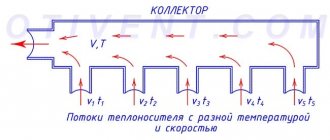
The distribution unit consists of two interconnected combs: the first directs the coolant to the appliances installed in the rooms, the second takes it back to the boiler
Collectors used for radiator heating, depending on the architectural and interior features of the room, can be connected in various ways.
According to the connection method, the radiator heating system can be made in any of the following versions:
- top connection;
- bottom connection;
- side installation;
- leading diagonally.
The lower connection method is still the most widespread. With such a layout, the contours hidden under the surface of the baseboard or floor are not so striking.
And calculations confirm that with a lower connection, all the advantages of private heating are fully manifested.
Each floor of the house is equipped with a collector for radiators. Install it in the center, masking the device in a niche or in a cabinet specially built for it on the wall.
The installation location should be chosen so that, if possible, branches of equal length are supplied to all devices.
If it is impossible to achieve equality of the rings connected to the collector, then each outlet is equipped with its own circulation pump.
In fact, all branches connected to the distribution node represent an independent circuit with its own shut-off valves, and sometimes automation.
A striking example of a collector heating scheme is water heated floors.
The collector wiring diagram ensures a uniform supply of heat to all rings of the water-heated floor system.
Underfloor heating pipelines are assembled from copper pipes or their plastic analogues; permanent fittings are used for connections.
Valves are installed in the heating rings, with the help of which they regulate the supply of coolant, and, if necessary, disconnect the “warm floors” from the general heating network.
A “warm floor” manifold is a structure that includes a series of pipe rings, which is laid under the floor covering
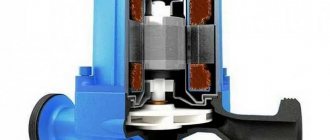
Such systems are always equipped with a circulation pump. It is placed in an intermediate collector unit at the entrance to the return pipe.
The number of pipes on the distribution unit depends on the number of rooms connected to one comb.
The number of collector groups is determined based on the length of the circuits. The calculations are based on the ratio in which 120 meters of pipeline are allocated to one collector group.
Type #2 - hydraulic arrow
When installing powerful and extensive heating systems, which are designed in residential buildings with a large area, distribution manifolds equipped with a thermo-hydraulic distributor or hydraulic switch .
When installing a connecting link, a heating boiler circuit is connected to it on one side, and radiator heating or “warm floors” on the other.
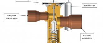
The hydraulic arrow is a vertical hollow pipe equipped at the ends with elliptical plugs, the main purpose of which is to equalize the pressure exerted on the coolant
The presence of a hydraulic distributor allows you to solve several problems at once:
- avoid sudden changes in temperature in the pipes, which have a detrimental effect on the service life of the system;
- by mixing and secondary circulation of part of the coolant, maintain a constant volume of boiler water, as well as save fuel and electricity;
- if necessary, compensate for the flow deficit in the secondary circuit.
Maintaining temperature balance is achieved due to the fact that the device allows you to separate the hydraulic circuit of the boiler from the secondary circuit.
Option for manufacturing a homemade manifold distributor, equipped with a hydraulic arrow, which is made of a steel square pipe and equipped with fittings
Optimal operation of a system equipped with a hydraulic arrow can be ensured if each circuit is equipped with its own circulation pump.
Type #3 - solar collector installations
Devices of this type are chosen when installing an autonomous water supply system in non-gasified areas where the level of solar radiation is quite high.
Solar-powered air combs operate through the greenhouse effect, converting sunlight into thermal energy
The design of solar installations is slightly different from traditional counterparts. In essence, they are a kind of greenhouses that accumulate solar energy.
The natural circulation of the coolant in them is carried out due to convection currents and under the action of fans attached to the absorbing plate.
The solar absorber is a small flat box covered with a black absorbent plate. This heat-receiving plate accumulates heat.
The accumulated heat is transferred to the coolant, which can be air or liquid circulating through the pipes.
The main purpose of the solar collector is to direct and redistribute the energy of the Sun to household needs and needs
On sale you can find moving collector systems powered by solar energy. Their design is designed in such a way that mirrors and heating elements “monitor” the movement of the sun, thanks to which its energy is absorbed to the maximum.
But due to the high cost of equipment, the use of solar installations as the main source of heating in the climate of even the southern regions of our country is unprofitable.
Therefore, they are more often used as an additional source of heat when installing heating systems using solid fuel and gas boilers.
What is it needed for?
When installing water pressure systems, there is a rule: the total diameter of all branches should not exceed the diameter of the supply pipe . In relation to heating equipment, this rule looks like this: if the diameter of the boiler outlet fitting is 1 inch, then the system allows two circuits with a pipe diameter of ½ inch. For a small house heated only with radiators, such a system will work effectively.
In fact, there are more heating circuits in a private house or cottage: heated floors, heating of several floors, utility rooms, and a garage. When they are connected through a tapping system, the pressure in each circuit will be insufficient to effectively heat the radiators, and the temperature in the house will not be comfortable.
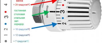
Therefore, branched heating systems are made using collector systems; this technique allows you to adjust each circuit separately and set the desired temperature in each room. So, for a garage, plus 10-15ºС is enough, and for a nursery, a temperature of about plus 23-25ºС is required. In addition, heated floors should not heat up more than 35-37 degrees, otherwise it will be unpleasant to walk on them, and the floor covering may become deformed. With the help of a manifold and shut-off temperature, this problem can also be solved.
Modifications of distributor combs
Today, there are many types of collectors for heating systems on the equipment market.
Manufacturers offer both connecting links of the simplest design, the design of which does not provide for the presence of auxiliary fittings for regulating the equipment, and manifold blocks with a full set of built-in elements.
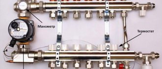
A collector block that includes all the necessary functional elements to create conditions for uninterrupted and high-performance operation of the heating system
The simple-to-use devices are brass models with one-inch branches, equipped with two connecting holes on the sides.
On the return collector, such devices have plugs, instead of which, in the case of “expanding” the system, additional devices can always be installed.
Intermediate assemblies that are more complex in design are equipped with ball valves. For each outlet they provide for the installation of shut-off control valves. Sophisticated, expensive models can be equipped with:
- flow meters , the main purpose of which is to regulate the flow of coolant in each loop;
- temperature sensors designed to monitor the temperature of each heating device;
- automatic air release valves
- electronic valves and mixers aimed at maintaining the programmed temperature.
The number of circuits, depending on the connected consumers, can vary from 2 to 10 pieces.
Regardless of the complexity and versatility of the equipment, materials that are resistant to external factors are used in the manufacture of manifold block combs
If we take the manufacturing material as a basis, then intermediate prefabricated collectors are:
- Brass - characterized by high performance parameters at an affordable price.
- Stainless steel structures are extremely durable. They can withstand high pressure with ease.
- Polypropylene - models made of polymer materials, although they have a low price, are inferior in all characteristics to their metal “brothers”.
Models made of metal are treated with anti-corrosion compounds and covered with thermal insulation to extend their service life and improve performance parameters.
Separating structures made of polymers are used in the construction of systems heated by boilers with a power of 13 to 35 kW
Parts of the device can be cast or equipped with collet clamps, allowing connection to metal-plastic pipes.
But experts do not advise choosing combs with collet clamps, since they often “sin” by leaking coolant at the valve connection points. This occurs due to rapid failure of the seal. And it is not always possible to replace it.
Collectors are used in single- and two-pipe heating schemes. In single-pipe systems, one comb supplies the heated coolant and receives the cooled one
Do it yourself
The distribution manifold for the heating system can be made independently from polypropylene or metal. The choice of material does not affect the functionality, so you should choose a material that is easier to install yourself.
To install a polypropylene collector assembly, you need a special device for welding polypropylene pipes; for metal ones, a welding inverter and skills to work with it.
Calculation and distribution of contours
- Before starting work, it is necessary to determine the required number of heating circuits and draw a drawing for their connection. It is advisable to allocate separate circuits for the following heating devices:
The geometric dimensions of the collector should provide ease and convenience of access to the shut-off and control equipment of each branch. On average, the distance between the layers is recommended to be kept within 10-15 cm, between the supply and return collectors - 20-30 cm.
Pipes for connecting heating radiators are usually made with a diameter of ½ inch, the collector itself is 1-1½ inches, matching them with the diameter of the boiler pipes. When connecting a gas or electric boiler, top and bottom connections of the supply and return pipes are allowed; for solid fuel boilers, only side connections are allowed.
Polypropylene knot
It is made from scraps and remnants of polypropylene pipes using fittings. The pipes are welded using a special apparatus. For the supply and return manifolds, a polypropylene pipe Ø32 mm and tees 32/32/16 mm are used, connecting them using a polypropylene welding machine. The mode is selected in advance using pipe scraps.
A 32/32/32 mm tee is installed at one end, to which a drain valve is connected from below, and an air valve from above. At the other end of the collector, an inlet valve is installed, to which the supply or return pipe leading to the boiler is connected.
Shut-off valves are connected to 16 mm taps on the supply manifold, and flow meters are connected to the return manifold. The resulting units are attached to the wall with brackets.
Assembly of brass fittings
In a similar way, you can assemble a manifold from ready-made brass fittings: tees, valves. They are collected using flax tow or liquid fixative according to a pre-prepared scheme. The advantages of such a collector are its small size and low price compared to a ready-made collector group. But assembly requires care and precision, otherwise leaks may occur during operation.
Recommendations for choosing wisely
The main difficulty lies not only in the installation of the collector itself, but also in the correct choice of equipment.
When choosing a comb model, you should focus on the following parameters:
- Maximum permissible pressure for this model. It determines the type of material from which the hydraulic valve can be made.
- Node throughput.
- Availability of auxiliary devices.
- Number of comb outlet pipes. It must correspond to the number of cooling circuits.
- Possibility of additional connection of elements.
All operational parameters are indicated in the product passport.
To install floor-by-floor independent heating circuits equipped with autonomous control, combs must be installed on each floor of the house.
When selecting and installing floor distributors, they are guided by the parameters of the “subsystem” that they are intended to serve.
Thanks to the floor-by-floor arrangement of the combs, if necessary, you can always turn off the heating of both several individual devices and the entire floor
This greatly simplifies the maintenance and repair of the heating system.
Since a collector block is not a cheap pleasure, in order to protect yourself from disappointment when the system quickly fails, when choosing a model, you should focus on products from trusted manufacturers.
You can safely trust such manufacturers as GREENoneTEC , Rehau , Soletrol , Oventrop and Meibes . In each series of leading European manufacturers you can select a complete set of necessary additional equipment.
Auxiliary elements and fittings for the collector block must also comply with GOST and TU.
As additional devices for connecting the manifold, you may need: 1 – automatic air vent, 2 – adapter, 3 – corner, 4 – tap, 5 – squeegee, 6 – another corner, 7 – pipe outlets
Each of the additional structural elements performs its own function:
- automatic air vent - installed if the unit and radiators are located on the same floor;
- adapter - required when installing an air vent with a diameter of ½ inch, provided that the manifold thread is ¾ inch.
- corner - will allow you to connect the pipes and direct the air vent upward.
- tap – necessary to connect the pipe coming from the boiler to the device;
- a squeegee equipped with a cap nut will allow, if necessary, to shut off the coolant supply and, by unscrewing the cap nut, disconnect the device.
If you intend to connect a water heated floor from the collector, you will additionally need to install a tap for refilling.
To fix the collector to the wall, you will also need clamps mounted on plastic dowels. When installing the structure, it is also permissible to use special brackets.
Such designs are convenient in that the upper manifold in them is pushed forward, so that the pipes of the unit do not interfere with the pipeline supply to the lower manifold.
Advantages of a collector circuit for distributing water supply pipes in an apartment
In apartments, simple water pipe installation is most often performed. There is a pipe coming from the riser. Then, with the help of tees, there are branches from it to plumbing fixtures. At the same time, few people know about another type of pipe routing - manifold. And in vain, because such a system has a number of advantages that need to be discussed.
But first we need to talk about the types of wiring that exist in plumbing today. The first type is tee wiring. In such a system, all consumers are connected from one pipe using tees. It is possible to install shut-off valves in front of each consumer in case of an emergency.
Collector wiring. This system has clear advantages over the tee system. A shut-off valve is installed at the entrance of the water supply to the apartment. The difference is that each device has a separately supplied pipe. In this case, all valves are concentrated in one place.
Sometimes you can find a mixed system. This means that it contains elements of tee wiring and collector wiring. For example, water can be supplied to the washbasin and bathtub from the collector (that is, a separate pipe for each consumer), and the toilet and bidet are connected via tee wiring.
Installation and connection rules
It is best to select and install a collector at the stage of design and installation of the heating system.
Such intermediate structures are installed in rooms protected from excess humidity. Most often, space is allocated for these purposes in the hallway, pantry or dressing room.
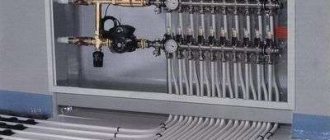
It is advisable to place the collector block in a metal cabinet specially designed for this purpose, equipped with holes in the side walls for pipe outlets
On sale there are overhead and built-in models of metal cabinets. Each model is equipped with a door and stampings on the sides.
In the absence of the opportunity to install a metal cabinet, it is easier to do it by fixing the device directly to the wall. The niche for arranging the collector block is placed at a low height relative to the floor.
There are essentially no generally accepted instructions for installing collector distribution circuits. But there are a number of main points regarding which experts have come to a common denominator:
- Availability of expansion tank . The volume of the structural element must be at least 10% of the total amount of water in the system.
- The presence of a circulation pump for each laid circuit . Regarding this element, not all experts are unanimous in their opinion. But still, if you plan to use several independent circuits, it is worth installing a separate unit for each of them.
An expansion tank is placed in front of the circulation pump on the return line. Thanks to this, it becomes less vulnerable to the turbulence of water flows that often occur in this place.
If a hydraulic arrow is used, the tank is mounted in front of the main pump, the main task of which is to ensure circulation in the small circuit.
The location of the circulation pump is not important. But, as practice shows, the service life of the device is somewhat higher on the “return” route.
The main thing during installation is to position the shaft strictly horizontally. If this condition is not met, the very first bubble of accumulated air will leave the unit without cooling and lubrication.
The process of assembling and connecting the collector system is clearly presented in the video block.
Pipeline laying options
The main pipe laying schemes during installation are zigzag and spiral volute, the latter provides more uniform heating and is considered the best in efficiency. When laying pipes, a certain distance between sections must be maintained; it depends on the layout and thickness of the screed; its typical value for the usual thickness of the cement-sand layer is in the range of 150 - 200 mm.
The distribution manifold is the main unit in an individual heating system containing two or more underfloor heating circuits; it performs the functions of distributing and mixing the coolant to reduce its temperature. During installation, a pipeline made of cross-linked or heat-resistant polyethylene is placed under a screed in the form of a zigzag or snail and connected to the combs using Eurocones, which ensure a quick and tight connection.