Features of collectors from various manufacturers
Rehau combs are excellent devices for balancing the system.
At the same time, they are resistant to leaching of alloy components and can be used for floor heating circuits in quantities from 2 to 12 pieces. The most modern models are equipped with flow meters, quick-acting taps on the supply pipe, and control valves on the return pipe. (See also: How to make heated floors at home with your own hands) The manifold cabinet for this device can be made in three modifications. One of the options is designed for hidden installation of a cabinet under a layer of plaster. The cabinet, intended for outdoor installation, is made of galvanized steel and has many modifications that differ in size.
Collectors produced by the Italian company FAR are widely used. This heating comb is used in many countries around the world due to its properties that meet most world standards. FAR manifolds are used for one-pipe and two-pipe heating systems, various types of materials from which devices and pipes are made. The product range of this company is surprisingly wide and varied: modular and non-regulating regulating manifolds, fittings for them and other components.
Use of materials is permitted only if there is an indexed link to the page with the material. For any questions please contact
Group: Forum participants
Messages: 200
Registration: 24.1.2007
User No: 5676
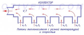
You can choose any temperature schedule - 15, 20 and 25 degrees C. Naturally, with an increase in delta T, the flow rate decreases, the diameters of the pipelines decrease, but the thermal pressure “delta Tm” also decreases - accordingly, this will lead to an increase in the total area of the heating devices. We need to count the costs. And the choice of pipeline diameters is regulated by the “noise limit” or the maximum speed of the carrier for each diameter.
Regarding the speed of movement of the carrier in the comb, if we recall the old Soviet systems, the concept of a comb and a collector was used extremely rarely; even in ITP, as the flow rate decreased, the diameter of the pipelines decreased.
Post edited by annuka
— 21.10.2007, 6:50
Today you can find innovative developments of heating systems, but water heating seems to always be in the lead. After all, such a system is effective and practical, most people are very happy with it. But every hydronic heating system can become less efficient over time. And then many begin to become interested in ways to modernize it.
These methods include a distribution heating manifold, which successfully replaces one- and two-pipe heating. Such a system can increase efficiency, ease of use and suitability for repairs. A mixing unit for heating is also used as an improvement to the underfloor heating system.
Heating distribution manifold
Areas of application of heating combs
The main purpose of the heating comb is to optimize and rationally distribute the coolant. Without a correctly designed and installed distribution manifold, the heating may not operate correctly. The comb allows you to use all the useful power of the boiler, while obtaining maximum efficiency of the entire system.
Collectors also allow you to include several consumer points in the system and be sure that the temperature of the coolant in all sections of the main will be the same. If you do not use a distribution comb, it often turns out that the radiator near the boiler is very hot, and the radiator, for example, on the second floor, is lukewarm.
This happens because the coolant cools down while it reaches the last battery. This effect can be avoided and the path of the coolant to the end consumer can be reduced by dividing it into specific circuits.
Advice. Very often, only two rooms are combined into a circuit, so the coolant passes through 2-3 radiators and returns to the boiler. Often, a heated floor is separated into a separate circuit, because the path of the coolant that it needs to go through the pipes, even in a room of 10 square meters. m., can be 100 m.
Types and qualifications of distribution combs
As mentioned above, the device is designed for cold and hot water. For even more convenient use, they are available in two colors - blue and red. This allows you to avoid confusion during installation and technical work, which makes life much easier in the future.
with 2, 3 or 4 outlets.
A significant advantage of collector pipe routing is that thanks to it it is possible to install a hidden gasket. This is ideal for the previously planned interior of the room in which the comb will be installed.
From a safety point of view, the distribution comb is one of the safest pipe layouts. After its installation, residents are not in danger of burst pipes and hot water leaking out, since it stabilizes its flow. If the building has several floors, wiring should be installed on each of them. The design of the device is very convenient, the pipes go from the risers directly to the distributor, and only then to all existing plumbing fixtures in the house
When installing, it is important to maintain an equal distance between the comb and the final device
Construction of a box for a heating manifold
- Circulation pump
This is one of the main parts of the manifold cabinet. It allows for the movement of water or other liquid (fuel) through the pipes of the device. The circulation pump allows you to regulate and deliver the exact amount of liquid required for heating to a room or household compartment.
Thanks to ordinary physics, the operation of the mechanism does not depend on the height of the building and the number of rooms in which the connected heating device is installed, therefore, for estates and estates, it is important to use a pump of average power.
Photo 2. Manifold cabinet with circulation pump. To operate the device, you must provide access to an electrical outlet.
Equipment that maintains a certain, set temperature in the rooms.
- Pressure gauge
- Flow meter
A unit that regulates and controls the flow of coolant through pipes . With the help of this device, the amount of hot and cold water in the mixing pipes is set and distributed in order to obtain the desired temperature in the room for mixing.
After turning off the heating equipment, the used water is regulated by a flow meter for further operation. Hot water is consumed faster than cold water, but it does not evaporate, allowing you to use it more than once.
- Air valve
When the heating structure is turned off, the water leaves, leaving the pipes empty. At the site of this devastation, a vacuum does not form, but air remains, which must be put somewhere when the heating device is turned on. This is where the air valve comes to the rescue. It allows air not to mix with water in large quantities , stopping this process for less evaporation of water and maintaining its volume.
Both distributor and regulator
At its core, a distribution comb is a centralized unit that allows the coolant to be distributed to its destination points. In a heating system, it performs no less important function than a circulation pump or the same boiler. It distributes heated water through the mains and regulates the temperature.
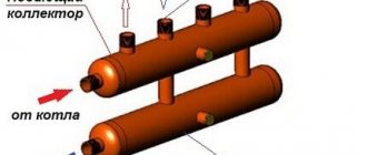
This diagram shows the general operating principle of a collector block consisting of two combs: through one, coolant is supplied to the system, and through the second it is returned
This unit can be called a temporary coolant storage tank. It can be compared to a barrel filled with water, from which the liquid flows not through one hole, but through several. In this case, the pressure of water flowing out of all holes is the same. This ability to simultaneously ensure uniform distribution of heated liquid is the basic principle of operation of the device.
Externally, the collector looks like an assembly of two combs, most often made of stainless steel or ferrous metal. The terminals available in it are intended for connecting heating devices to it. The number of such outputs must correspond to the number of heating devices served. If the number of these devices increases, the unit can be expanded, so the device can be considered dimensionless.
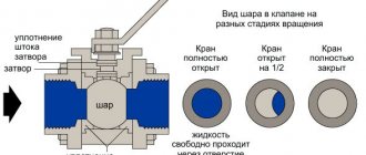
In addition to the leads, each comb is equipped with locking mechanisms. These can be two types of taps installed at the outlet:
- Cutting off. Such taps make it possible to completely stop the supply of coolant from the general system to its individual circuits.
- Regulatory. With the help of these taps, the volume of water supplied to the circuits can be reduced or increased.
The manifold includes valves for draining water and releasing air. It is also most convenient to place measuring equipment in the form of heat control meters here. In this case, everything that is necessary for the effective operation of this node will be in one place.
Why are there two combs in the manifold block? One serves to supply coolant to the circuits, and the second is responsible for collecting already cooled water (return) from the same circuits. All elements necessary for effective operation must be on each of the combs.
Pros and cons of collector systems
The main advantage associated with the use of collector-type systems is the ease of control and operation. This is due to the fact that each of the elements can be controlled both centrally and individually. Consequently, it is possible to set the temperature for each specific room, and, if necessary, completely deactivate a device or group of devices. Moreover, this will not affect other parts of the system.
Video – Collector heating system
Each of the branches that make up the node must power only one battery (or, alternatively, a separate group of batteries), so the diameter can be insignificant. If necessary, using a collector, you can equip several circuits with different temperature parameters at once. This became possible thanks to the advent of a hydraulic arrow - a type of comb, which is a similar tube, but of a larger diameter.
This arrow is installed differently from a standard manifold - a kind of short circuit is created in the gap between the “return” and the supply. The liquid in the initial circuit will be permanently heated by the boiler and smoothly move inside the hydraulic arrow, as a result of which different temperature and coolant pressure indicators are demonstrated.
But there are, of course, disadvantages. First of all, buying a distribution comb is a very expensive pleasure and this is probably the only reason why these devices scare away potential buyers. The fact is that high-quality steel is used in the production process, which is why the products are much more expensive than steel pipes. In addition, for installation you will also need high-quality shut-off valves (the number of them depends on the number of circuits).
Another drawback is the mandatory presence of a circulation pump, without which the comb simply will not be able to function (read: additional electricity costs).
Is it possible to make a heating collector with your own hands?
Sometimes it happens that the autonomous heating in your own home does not work very efficiently. It seems that the boiler power was selected correctly, the piping was done correctly, and all installation work was carried out at a professional level, but the temperature in the house is not what you would like. What to do in this case? There is only one way out - install a distribution manifold. By the way, there is no need to buy it ready-made, the design of the collector is not very complicated, so making it yourself is not the biggest problem. So, in this article we will answer one question: how to make a distribution manifold with your own hands?
How much will it cost to install a hydraulic arrow with a manifold?
We looked at what a hydraulic arrow in heating is and why it is needed. Now let’s try to figure out how much it will cost to install such a structure together with a collector and when it is necessary to resort to such a service.
The hydraulic separator and manifold themselves are not cheap components. In addition, their installation entails a number of additional costs. Here are the average prices that exist today on the market for these services:
- Hydraulic separator (factory production) – 200 euros;
- Collector (factory) – 300 euros;
- Trims (taps, fittings) – 100 euros;
- Controller (needed to control pumps outside the jurisdiction of the boiler) – 400 euros;
- Installer services (25% of the cost of materials) – 250 euros.
The total is 1250 euros - a pretty decent amount. Therefore, before installing a hydraulic arrow, you need to make sure that it is really necessary. If the installation specialist is not committed, then he will recommend installing a separator only if there are three or more heating circuits (excluding the boiler).
Of course, you can use a hydraulic gun with a home-made manifold, the manufacturing scheme of which will not differ in any way from the factory version. However, the quality of the material and welds is unlikely to meet technical standards. By saving on materials, you can ultimately significantly reduce the reliability of the system. And it’s good if the breakdown occurs not at the height of the heating season.
Polypropylene hydraulic separator - a simple but unreliable option
What conclusion can be drawn from this article? Firstly, the versatility of the hydraulic gun, which is so often talked about, is too exaggerated. It should be used only in one case - to coordinate the operation of several pumps with different capacities. Secondly, for reliable operation of the system, it is better to use a separator with a factory-made manifold, and entrust the installation to specialists whose goal is not to enrich themselves at the expense of clients, but to actually optimize the operation of autonomous heating.
How to make a distribution manifold yourself
For a good craftsman, making a homemade comb from metal or polypropylene will not be particularly difficult. Judge for yourself: a large-diameter steel pipe is plugged at both ends, after which connecting fittings with the thread that is most convenient for you are welded to it. The collector is then pressure tested for the permeability of the welds and painted over a layer of primer.
When performing this work, it is important to maintain the size and diameter of the pipes. You can be guided by this rule: the diameter of the collectors must be selected so that it is three times the diameter of the connected pipelines
In case you take profile pipes for production, we note that this proportion is also observed in relation to the cross-sectional area. To comply with the remaining dimensions, you can take the following diagram as a basis:
There is another option for selecting the diameter of the comb; it was discussed above in the example of a factory product. If the thermal power of the home heating system does not exceed 50 kW, then feel free to take a DN80 pipe, and above 50 to 100 kW, make a manifold from a DN100 pipe. In this case, the dimensions of the fittings do not need to be made three times smaller; take them in accordance with the hydraulic calculation.
A little more work needs to be done to make a comb from polypropylene tees. Such products are becoming more and more popular due to their low cost. You will only have to spend money on tees; all other parts will be inexpensive. By the way, similar collectors are already available for sale in assembled form.
Another thing is that a polypropylene comb, assembled with your own hands, is not able to withstand the high temperature of the water in the heating system. If an emergency occurs, the solder joints will immediately leak. This is quite likely when the house is heated with a solid fuel boiler, then the entire piping should be made of steel or copper.
Installation rules
A manifold with a hydraulic arrow reduces the risk of water hammer in the heating system.
The comb is fixed to the wall using brackets, then the main pipes are attached to the end and proceed to the piping stage.
The comb can be mounted in two ways: without a hydraulic arrow or with pressure equalization. In the first case, a homemade or purchased collector will serve several circuit elements, where the temperature of the coolant will not be adjusted and will remain at the same level. Each circuit is connected directly to the element and one pump is connected to it for circulation. All equipment parameters must correspond to the performance of the heating system and the pressure of the coolant.
The pressure equalization method is needed when it is necessary to ensure the same temperature at all points of consumption. For example, in batteries it should be kept within 50-80 degrees, in systems for heated floors from 40 to 50 degrees.
The hydraulic arrow is a piece of pipe, which is sealed on both sides and supplemented with several pipes. The first pair is needed to connect the hydraulic arrow to the boiler equipment, the second pair is needed to connect the combs. This is a convenient barrier that creates an area for low hydraulic resistance and liquid collection.
How to build a collector yourself?
You can buy a ready-made connection, choosing one that would approximately meet the needs of your home. But achieving an exact match is quite difficult. Therefore, it is better to make a heating comb yourself. Let's figure out what is needed for this.
Planning stage
There are a number of parameters of the heating system of the house that you should know when building a unit.
- The number of circuits through which heated water will pass.
- The number and technical characteristics of the heating equipment included in the scheme.
- Additional equipment involved in installation. This refers to pressure gauges, thermometers, taps, storage tanks, valves, pumps, etc.
It is also necessary to provide for the possibility of increasing the load if over time it is necessary to build in elements that were not taken into account in advance. This could be, for example, solar panels or a heat pump.
It is necessary to foresee in advance not only the number of circuits operating in the heating system, but also additional equipment that will be included in the overall scheme
Determining the block design
The design of the future node depends on the connection point of each circuit. After all, there are some connection nuances that cannot be ignored.
- Boilers (electric and gas) must be connected to the comb from above or below.
- The circulation pump should be connected from the end of the structure.
- Solid fuel units and indirect heating boilers also need to be cut in from the end.
- The supply circuits of the heating system are connected from below or from above.
For clarity, it is necessary to make a drawing of the future compact and neat unit. This will help determine the quantity and types of materials we will need. All necessary dimensions and threaded connections with thread pitch are also applied to the drawing. All circuits should be marked to guide the drawing when connecting.
This drawing shows a four-way manifold. You may not make a drawing and will limit yourself to a sketch, but do not forget to put on it all the dimensions necessary for the work
The distance between the nozzles of both combs should be from 10 to 20 cm. These are the optimal parameters for maintenance. The distance between the supply and return combs themselves should be within the same limits.
Sequence of work
To make both combs, not only round, but also square pipes can be used. The sequence of work performed is as follows:
- In full accordance with the parameters indicated on the drawing, we purchase all the necessary materials.
- According to the drawing, we make the connection by welding pipes, taking into account their subsequent functions. Welding areas should be cleaned with a wire brush and degreased.
- Testing a homemade unit is a necessary stage of work. To do this, all pipes are hermetically sealed except one, through which hot water is poured into the system. Let's take a good look at all the joints: they shouldn't leak.
- Now the collector can be painted and dried thoroughly.
- Next, you should connect pipes, locking mechanisms and control equipment to it.
After this, the device is ready for use
This will differ favorably from purchased products in that it is built taking into account the needs of a particular home, and this is very important for its further operation. Of course, a high-quality and functional device can only be obtained if the master knows how to handle a welding machine and metalworking tools
In order for a homemade collector block to work more efficiently than a purchased one, the master needs to be able to handle both welding equipment and plumbing tools
You can learn how to make a polypropylene manifold by watching this video:
Heating rooms using water heated floors is considered one of the most effective ways in terms of energy savings and uniform heat distribution. As you know, heating is carried out through pipes with coolant laid in a screed. Each room is a separate closed circuit, or even several. Their operation is controlled by one common unit - a comb for heated floors. Information about how this unit functions, the nuances of its assembly and regulation is brought to your attention in this article.
Installation features and cost
First of all, you need to choose a place to mount the collector. It is best to install this equipment in such a way that it is located at a minimum distance from the regulated heating circuits.
In height, the installation should be higher than the heating pipes. Otherwise, it will be difficult to bleed off any air that may be in the pipes. To place the equipment you need to install a special cabinet.
It can be open or closed. In the first case, it is practically a metal frame, in the second it is a plastic or wooden cabinet. It is most convenient to equip a niche in the wall for this purpose.
Install the collector strictly vertically. Outgoing pipes are first connected to it in series, then incoming ones. The installation and connection itself is quite complex. To do this, it is advisable to use the services of a professional.
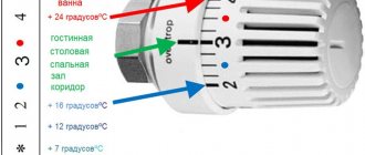
The important part is adjusting the valves. When sold, the device is accompanied by a diagram of their adjustment, which is made in the form of a special table. Comb for heated floor Giacomini. To carry out this operation, you need to remove the cap from each valve (this, of course, must be done before connecting the water to the collector)
Then, use a special hex wrench to tighten it completely. After this, in accordance with the table, open the valve to the required number of revolutions.
To carry out this operation, you need to remove the cap from each valve (this, of course, must be done before connecting the water to the collector). Then, use a special hex wrench to tighten it completely. After this, in accordance with the table, open the valve to the required number of revolutions.
The adjustment will allow the comb to work reliably and balanced for a long time.
Here are approximate prices for various configurations:
- For a double-circuit comb the price will be 15170 rudders. A circulation pump and an automation kit for regulating the movement of the coolant are included here.
- A Giacomini comb for two circuits will cost 17,472 rubles.
- A comb for four circuits, equipped with flow meters, will cost 16,650 rubles.
- A manifold for underfloor heating for 4 circuits of the ROSSWEINER system is sold at a price of 13,660 rubles.
It is recommended to buy products that belong to a well-known and reliable brand manufacturer. This allows parts to be replaced or supplemented with 100% compatibility.
If the apartment has several heating systems for underfloor heating, then several combs may be needed.
Comb for water heated floors operating principle
- normalize water temperature;
- distribute the liquid along the contours.
In heating boilers, the liquid is heated to 60 - 90 °C and disperses hot along the circuit.
For obvious reasons, it is impossible to pass such a hot coolant into a warm floor.
Lowering the temperature is one of the main tasks implemented in the collector unit. Temperature reduction can occur in two ways:
Mixing cooled coolant with hot fluid is the most popular method. Mixing occurs in a three-way valve. After the circulation pump drives the liquid through the circuit, it cools down. It is this cooled return that is added to the hot coolant. The proportions of both flows are checked by a thermal head. Its working part is installed on the valve itself, and the sensor is installed on the supply.
Instead of a thermal head there may be a servo drive. And for stable heating systems, when the boiler produces a relatively uniform temperature, you can set the three-way valve to one position, attach a thermometer to it and control the degrees manually.
Main elements of the collector unit
Without a circulation pump, the water floor circuit will not work. Also, if you place the pump before the three-way valve, the coolant will not enter the floor coil, but will flow in a small circle where there is less resistance.
Temperature limitation is implemented by installing a special thermal head into the system, which measures the temperature of the coolant. Outwardly, it is similar to a radiator thermostat, but is fundamentally different from the latter, which measures the air temperature in the room.
A person sets a value that is comfortable for himself, and the device, detecting exceeding the threshold, limits the clearance inside the device, reducing the flow of coolant.
Warm floors made in Russia are in increasing demand. Warm floor national comfort - reviews and cost.
What you should pay attention to when choosing a manifold for a heated floor, we’ll tell you here
Operating principle of the collector system
The manifold is a metal comb with leads for connecting pipes and devices. The collector heating system is two-pipe. Hot water is supplied through one comb, and pipes that collect cooled water (return) are connected to the other.
The collector heating system has a closed expansion tank and a circulation pump that moves the coolant. The minimum volume of the expansion tank is equal to at least 10% of the total volume of all heating devices. The pump is installed on any of the pipelines leading to the collectors.
The collectors are installed in special cabinets, which are mounted in wall niches or in a separate room. The collector cabinets should be located at approximately the same distance from each heating device. Pipes can be connected to radiators from above, from the side and from below. The most widespread is the lower pipe connection to radiators. This option provides the best opportunity to hide pipes in the floor. A shut-off valve is installed on each hydraulic circuit coming from the collector, which makes it possible to turn off any radiator without disturbing the operation of the heating system. A valve is installed on each radiator to release accumulated air - a Mayevsky valve, or on the manifold - air release valves. Heat meters and drain valves can also be installed on the collector.
Each hydraulic circuit located after the manifolds is an independent system. This made it possible to create heated floors. These are floors in which pipes are laid in parallel or in the form of spirals, which heat the floor surface. The pipes are laid on a heat-insulating pad, connected to the collector and, after checking the tightness of the pipelines, they are filled with concrete. The height of the screed should not exceed 7 cm. The laying pitch and diameter of the pipes are determined by calculation. The length of one heating spiral should not exceed 90 m. Basically, metal-plastic pipes are used for heated floors, which easily accept any curvature.
When heating a warm floor, the temperature decreases according to the height of the room, and when installing radiators, on the contrary, the higher, the warmer.
Modifications of distributor combs
Today, there are many types of collectors for heating systems on the equipment market.
Manufacturers offer both connecting links of the simplest design, the design of which does not provide for the presence of auxiliary fittings for regulating the equipment, and manifold blocks with a full set of built-in elements.
A collector block that includes all the necessary functional elements to create conditions for uninterrupted and high-performance operation of the heating system
The simple-to-use devices are brass models with one-inch branches, equipped with two connecting holes on the sides.
On the return collector, such devices have plugs, instead of which, in the case of “expanding” the system, additional devices can always be installed.
Intermediate assemblies that are more complex in design are equipped with ball valves. For each outlet they provide for the installation of shut-off control valves. Sophisticated, expensive models can be equipped with:
- flow meters, the main purpose of which is to regulate the flow of coolant in each loop;
- thermal sensors designed to monitor the temperature of each heating device;
- automatic air release valves for draining water;
- electronic valves and mixers aimed at maintaining the programmed temperature.
The number of circuits, depending on the connected consumers, can vary from 2 to 10 pieces.
Regardless of the complexity and versatility of the equipment, materials that are resistant to external factors are used in the manufacture of manifold block combs
If we take the manufacturing material as a basis, then intermediate prefabricated collectors are:
- Brass - characterized by high performance parameters at an affordable price.
- Stainless steel structures are extremely durable. They can withstand high pressure with ease.
- Polypropylene - models made of polymer materials, although they have a low price, are inferior in all characteristics to their metal “brothers”.
Models made of metal are treated with anti-corrosion compounds and covered with thermal insulation to extend their service life and improve performance parameters.
Separating structures made of polymers are used in the construction of systems heated by boilers with a power of 13 to 35 kW
Parts of the device can be cast or equipped with collet clamps, allowing connection to metal-plastic pipes.
But experts do not advise choosing combs with collet clamps, since they often “sin” by leaking coolant at the valve connection points. This occurs due to rapid failure of the seal. And it is not always possible to replace it.
Collectors are used in single- and two-pipe heating schemes. In single-pipe systems, one comb supplies the heated coolant and receives the cooled one
Calculation of comb throughput
The calculation of the parameters of the distribution comb includes determining its length, the cross-sectional area of its cross-section and pipes, and the number of heat supply circuits. It is better if the calculations are done by engineers using computer programs; in a simplified version, they are only suitable at the preliminary design stage.
In order to maintain hydraulic balance, the diameters of the inlet and outlet manifold combs must match, and the total throughput capacity of the nozzles must be equal to the same parameter of the collector pipe (the rule of total sections):
n=n1+n2+n3+n4,
Where:
- n is the cross-sectional area of the collector4
- n1,n2,n3,n4 - cross-sectional areas of the pipes.
The choice of comb must correspond to the maximum thermal output of the heating system. What power the factory product is designed for is written in the technical data sheet.
For example, a distribution pipe diameter of 90 mm is used for a power not exceeding 50 kW, and if the power is twice as high, the diameter will have to be increased to 110 mm. This is the only way to eliminate the risk of unbalancing the heating system.
The cross-section of the collector pipe is equal to 3 diameters of the connected pipes, the distance between the supply and return combs is 6 diameters, the distance of the pipes from each other is 3 diameters
The 3-diameter rule is also useful (see picture above). As for calculating the performance of the circulation pump, the specific water consumption in the heating system is taken as the basis.
Each pump is calculated separately - per circuit and for the entire system. The figures obtained in the calculation are rounded up. A little extra power is better than too little.
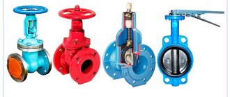
Types of heating combs
In stores you can purchase heating manifolds that differ in the number of connected circuits, materials of manufacture, the presence of thermal heads or flow meters, manufacturer and a host of other characteristics. However, in general they can be divided into three main groups:
- manifold for boiler room;
- hydraulic arrow;
- local combs.
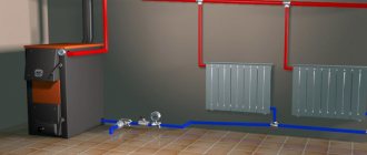
Heating distribution manifold for boiler room
A manifold for a boiler room is usually mounted from large-diameter metal pipes and is equipped with several pumps to circulate fluid through the system. This collector system consists of a supply comb, through which coolant is supplied to the heating system of the entire house, and a comb, which receives the cooled liquid and sends it to the boiler for heating. Pumps with shut-off valves are installed on the supply comb, and shut-off valves are usually installed on the receiving comb.
A necessary element of complex heating systems is a hydraulic arrow, which maintains the best temperature difference in the supply and exhaust circuits. Thanks to this difference, the operation of the heat generator installation is maintained with the lowest energy consumption. We will talk more about the hydraulic gun later in the article.
The boiler room manifold is also equipped with pressure monitoring devices and temperature sensors to monitor the operation of all elements. Such an element has fairly decent dimensions and is usually installed in a special room.
Hydroarrow
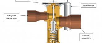
A hydraulic arrow is a device that is used to equalize pressure and temperature in a heating system. In the simplest case, a heating boiler circuit approaches it on one side, and a radiator circuit on the other, thus performing the function of a distribution manifold.
For more complex systems, a hydraulic arrow is installed in the boiler room in front of the distribution manifold, performing the same function - equalizing pressure in the system.
Structurally, the hydraulic arrow is made in the form of a vertical pipe, at the ends of which elliptical plugs are installed. If the coolant leaving the boiler has a temperature, and therefore a pressure, higher than necessary, then when it enters the hydraulic arrow, part of it goes into the heating circuit, and part of it is mixed with the cooled coolant from the return. Thus, stabilization and self-regulation of temperature and pressure in the system occurs. Visually, various cases of fluid flow are shown in the diagram:
The hydraulic distributor allows you to:
- avoid sudden temperature fluctuations that reduce the service life of the system;
- maintain the volume of water in the boiler heat exchanger at a constant level;
- maintain thermal equilibrium by separating the hydraulic circuit of the heat generator from the general system main.
The most complete optimization of the operation of a system with an installed hydraulic arrow is achieved through the use of a separate circulation pump for each circuit.
Heating comb
The distribution manifold for heating, unlike the boiler manifold, has much more modest dimensions, however, it performs similar functions. With the help of such a comb, the coolant coming from the boiler room is distributed either to consumers on the floor, or to various groups of consumers (underfloor heating collector, heating radiator collector).
The principle of operation is also somewhat different. If in the boiler manifold assembly the cooled coolant is completely replaced with heated liquid, then in the distribution comb they are also mixed and fed back into the system.
The functions of the hydraulic arrow in the combs are usually assigned to an additional circulation pump. With its help, the local heat-carrying fluid moves in a circle, entraining an additional portion of the heated coolant due to the different temperatures of the flows. At the same time, chilled water or antifreeze enters the main line. In accordance with this operating principle, a dosed amount of coolant is distributed into one or another heating circuit.
The distribution comb of the heating system is usually installed when there are three or more thermal appliances in one room and when a heated floor is installed. It helps to optimize the functioning of the entire complex and reduce the energy consumption of the heat generator.
Both the collector unit in the mini-boiler room and the distribution comb at first glance perform overlapping functions, but it is their joint use that makes the operation of the entire heating complex highly efficient.
Advantages of a collector heating system
The main advantages are the ease of control of the design, in particular:
- Each circuit element can be controlled independently and centrally. This means that in the house the owner sets the temperature of each room and has the opportunity to turn off the radiator or group of radiators from heating altogether.
- Reduced costs. Due to the supply of coolant to only one battery, smaller diameter pipes are suitable for forming a pipeline. Plus the ability to disconnect the battery from the heat supply - together you get some good savings. The liner is most often recessed into the screed, taking into account the minimum distance from the boiler and radiator.
- You can set up several circuits with different heating parameters, including temperature changes, using a hydraulic arrow.
Also, when installing a collector for a heating system, you need to take into account the disadvantages:
- increased energy consumption;
- difficulties in equipping beam distribution and recessing devices into the screed;
- increased hydraulic resistance in the system.
When arranging independent heat supply to different circuits, it becomes necessary to use circulation pumps for each circuit, which means that the system becomes energy-dependent.
Principle of operation of the collector
The main purpose of the device is to uniformly supply heat flows from the main line along the circuit circuits and to the heating radiators, as well as to supply return water to the boiler. The device acts as an intermediate distribution unit and consists of a supply and return comb. In this case, the supply element is responsible for supplying coolant to the circuit, and the return element is responsible for returning the liquid to the boiler.
From each comb there are leads for connecting circuits leading to heating devices. The distribution comb of the heating system with leads can be supplemented with shut-off valves, which help regulate the pressure inside the circuits and, if it is necessary to carry out repairs or reduce the heating intensity, shut off the coolant supply to a separate branch.
The principle of operation is simple - a thermal collector for heating a house transfers coolant through a supply comb to the circuits, while inside the intermediate unit the coolant circulation rate is reduced due to the increased internal diameter of the structure, and this ensures uniform redistribution across all outlets.
The coolant is directed through connecting pipes, enters separate circuits and is transported to heating radiators or to a heated floor grid. Then the structure is heated, and the liquid is redirected through another pipe to the collecting comb of the collector. From here the water flows to the heat generator.
Why do you need a distribution comb?
During the construction of old-type houses and apartments, main pipe routing (sequential laying) was used, which is inconvenient for modern times. Many people faced the problem of uneven heating of apartments, and, unfortunately, no one could cope with the different pressures in the pipes. But today the problem has been solved; a solution called a distribution comb has arrived on the modern market. Unfortunately, in order to correct the situation in houses and apartments with a ready-made heating system, you will have to change the pipe layout to a collector system. If you are just planning to heat the room, this article will be useful for you.
What will change after installing the distribution comb:
- The pressure in the pipes will be equalized throughout the room.
- The problem of sudden cooling of water in the bathroom when you turn on the tap in another place will disappear
- The house will be heated evenly
This is only part of all the advantages of manifold pipe routing after installing the comb. To minimize uneven water supply, the comb should be installed for both cold and hot water. Special taps are installed on it; they allow you to shut off the flow of water in a separate unit; this is convenient in the event of a leak in the toilet or a broken tap in the bathroom.
Calculation of the actual power of the solar collector
Manufacturers indicate the maximum power of the solar collector at full illumination, facing south and oriented perpendicular to the sun at noon. But it is not always possible to direct the panels this way, especially if they are installed on the roof of a house.
Below are formulas that are universal and can be used both to calculate the number of collectors and to calculate the total area in square meters.
Calculation of solar collector efficiency by direction
The basic thermal performance of a solar flat plate or vacuum collector can be calculated using the following formula:
Pv = sin A x Pmax x S
Values:
- Pv – solar collector power;
- A – angle of deviation of the solar collector plane from the direction to the south;
- Pmax is the average insolation level in your region during the cold season.
Even if the sun is not hidden by clouds, the level of insolation changes throughout the day, which determines the performance of the collector. The average data can be seen in this graph:
The data in the illustration on the daily level of insolation are averaged, but they allow you to understand the difference between the amount of thermal energy that can be obtained at different times of the year.
The maximum level of insolation in winter is on average 3-4 times less than in summer. The amount of solar energy that a solar collector can receive per day in winter is 5-7 times lower (depending on latitude) than in summer.
Calculation of solar collector performance based on installation angle
The optimal angle for installing a solar collector for heating a house in winter is so that it is perpendicular to the sun's rays at 10 o'clock in the morning. This way it can collect maximum thermal energy during daylight hours.
Sometimes it is not possible to do this (when installed on the roof, mounted on standard supports). Due to deviations from the optimal angle, the energy efficiency of the collector may change. It can be calculated using the following formula:
Pm = sin(180 - A - B) x Pv
Values:
- Pm – solar collector productivity;
- A – angle between the collector and the ground plane;
- B – the height of the sun above the horizon at 10 am;
- Pv – previously found power.
If you have the ability to orient the solar collector so that it is perpendicular to the sun, then:
Pm = Pv
The photograph shows the angle of inclination of the solar collector, which must be used in the calculations.
Features of flat panels
A flat solar collector has small heat losses through the rear wall, which average 5 W per square meter. Therefore, from the previously obtained value of the real power P, it is necessary to subtract 5 W per square meter of area.
The solar radiation absorption level of a flat solar collector is below 100%. This must be taken into account when calculating its thermal power. If the panel absorbs only 95%, then its real power is:
P = Pm x 0.95 x S
Values:
- Pm – collector power from the formula above;
- P – real reservoir performance;
- S – collector area.
Vacuum manifold performance
Manufacturers of vacuum manifolds may specify the manifold capacity without taking into account the distance between the tubes. To determine the actual surface area of the tubes and the performance of the vacuum manifold, we use the formula:
P = Pm x D / L
Designations:
- P – actual performance of the solar collector;
- Pm – collector power, calculated earlier;
- D – diameter of vacuum tubes;
- L – distance between tubes.
Thermodynamic solar panels
With this type of collectors everything is much more complicated. Now they are not very common, manufacturers are experimenting with materials and selective coating. Different models differ in the level of absorption and heat loss.
In general, thermodynamic solar panels have the right to life. But we would not recommend installing heating with their help. There are few effective models on the market, and those that exist are sold at inflated prices.