The principle of operation of the valve is very simple - the valve moves to one of the extreme positions using the operator’s influence. This is where the high reliability and durability of this type of shut-off valve come from. But few people know that to achieve such ease of operation, a number of specialists worked tirelessly. In the process of manufacturing one valve, steelworkers, foundries, stampers, rollers, lathes, and design engineers are involved. Each detail is verified to millimeter precision to prevent accidents and production stops.
In this review you will get acquainted with the basic principles of valve manufacturing. What metals are used? How are sealing surfaces applied? What are the bodies cast from? What steel is the valve stem made of?
How the wedge is assembled and much more. The information will be useful both for chief technologists of enterprises and for working personnel servicing pipelines.
Application area
Valves are used as shut-off and flow-regulating fittings in pipes; sometimes they are used to control the flow volume by reducing the nominal diameter of the passage.
Valves are rarely used in everyday life; they are mainly used to regulate water and gas supply in housing and communal services, in pipelines for transporting gas, oil, food and chemical industries when supplying technological components in the production process.
Shut-off elements are used on pipelines with large nominal bore diameters; the materials used are inexpensive ferrous and non-ferrous metals in various combinations.
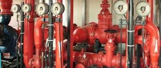
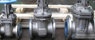
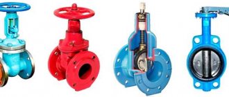
Fig.1 Valves for water supply pipelines
What are valves: purpose and main structural elements
A valve is a type of pipeline fitting designed to block or regulate the flow of a substance passing through a pipeline. They can work in environments with gaseous, granular, and liquid substances of varying viscosity and chemical activity.
The main structural elements in a valve system of any design are:
- Frame. It consists of a main part and a cover, the first is placed directly in the line, and the second is used to fasten and control the movement of the shut-off element. The body is made of metal: steel alloys, stainless steel, brass, aluminum, malleable cast iron, the latter is coated with anti-corrosion mica-containing paints or epoxy primers.
- Constipation. The element (damper) is designed in the form of a metal wedge, gate, disk or flexible pipe made of elastic materials; to increase the tightness, the metal is sometimes coated with rubber (elastomer). When moving, the assembly fits tightly into the profile seat located in the body and seals the channel.
- Drive system. Designed to control the movement of the damper in the assembly, it is represented by mechanical structures in the form of a flywheel moving on a retractable or stationary rod; pneumatic, electric and hydraulic drives are also used.
Rice. 2 Pipeline valves made of steel - parameters according to GOST 9698-86
Specification of materials
| p/p | Name | Qty | Material |
| 1 | Frame | 1 | Gray cast iron SCh20 |
| 2 | Lid | 1 | Gray cast iron SCh20 |
| 3 | Disk | 2 | Gray cast iron SCh20 |
| 4 | Wedge | 1 | DN50-150: Steel 25L |
| 5 | Wedge | 1 | DN200: Gray cast iron SCh20 |
| 6 | Stuffing box | 1 | Gray cast iron SCh20 |
| 7 | Flywheel | 1 | Gray cast iron SCh20 |
| 8 | screw | 1 | Gray cast iron SCh20 |
| 9 | Threaded bushing | 1 | Brass LS 59-1 |
| 10 | Spindle | 1 | Steel 45 |
| 11 | Pad | 1 | Paronitis PON-B |
| 12 | Packing rings | n/DN | Thermally expanded graphite |
Advantages of valves
The main parameters of valves are regulated by GOST 9698-86; products used in industry have the following features:
- Simplicity of design. The body consists of a main part placed in the line using a flange or coupling threaded connection (for small diameters), its cover is secured with nuts or bolts - this simplifies the procedure for installing, dismantling and repairing the device.
- High technical characteristics. Sliding valves, depending on the purpose and operating conditions, can withstand operating temperatures from -60 to +565 C., pressure from 0.16 to 25 MPa. (1.6 - 250 bar.) in steel structures. In this case, the pressure limit for cast iron is 25 bar, for products made of non-ferrous metals - 40 bar.
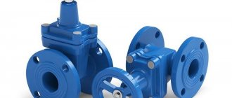
Rice. 3 Shut-off cast iron flange fittings
- Versatility. The devices can operate in pipelines for any purpose with high chemical activity of the transferred substances, and are designed for use in pipelines with diameters from 15 to 2000 mm.
- High hydraulic characteristics. Gate valves are selected according to the internal diameter of the pipelines, which has standard values, so they do not affect the hydraulic resistance in the line. The smooth movement of the damper when blocking the flow of the transported substance avoids water hammer in the system. The design of the sliding elements and the body seat is designed to create high tightness of the closed channel.
- Good maintainability. Installation and repair of fittings and fittings with valves is easy to carry out if you have simple tools and components - adjustable plumbing wrenches, gaskets. In case of wear, valves and gaskets can simply be removed and replaced with new ones.
- Long service life. Body parts and valves are made of strong, durable materials designed for use in a specific working environment; internal valves are made of corrosion-resistant metals - this significantly increases their service life.
Repair features
Over time, the valve may require repair work, since the moving parts of the mechanism periodically become unusable.
Why valves fail
The main causes of failure include:
- Loss of a sealed connection between the pipeline and the body of the valve. This type of failure occurs due to violations of the installation technology or deformation of the seal.
- Depressurization between the seal and the rod. The cause of the breakdown is wear of the oil seal.
- Loss of tightness between the valve and the body part. The cause of this type of breakdown is the regular transit of contaminated liquids. Dirt particles have a detrimental effect on the O-rings, gradually deforming them. Dirt can also accumulate on the internal surfaces of the mechanism and prevent the lid from sealing tightly. If this type of failure occurs, the valve will need to be completely dismantled or partially disassembled.
We recommend that you read: How to make a high-quality boiler for a bath with your own hands?
Partial repair work is carried out after the pipeline is shut off.
Then you need to remove the housing cover and disassemble the oil seal cover.
Determine the breakdown and fix it.
Dismantling the device
Complete dismantling of the valve is carried out according to the following plan:
- Remove the flywheel element with the running nut.
- Unscrew the locking screws on the housing cover.
- Remove flange connections.
- Remove the stem, clean the valve and seats.
- Replace sealing elements.
Reassembly of the repaired mechanism is carried out in strict reverse order.
Then they proceed to testing, for this they will try to completely block the flow of liquid in the pipeline, closing the flywheel all the way.
Minuses
In the manufacture of shut-off valves, cast iron is often used to reduce costs; such designs have the following disadvantages:
- The high weight of the valves makes it difficult to install units with large pipeline diameters—several workers or special lifting equipment may be needed to hold the massive part. For example, the weight of a cast iron constipation with a nominal bore of 1600 mm. According to GOST 9698-86 it is 10025 kg.
- Cast iron is a corrosion-unresistant material; over time, its inner surface rusts, becomes covered with shells and limescale - this leads to a failure of sealing when the flow is blocked.
- Another disadvantage of cast iron is its fragility, which leads to irreversible damage to the product under strong impacts.
- A cheap gland seal with packing, which is used in budget cast iron products, is not sufficiently tight compared to modern mechanical seals - during its operation, leaks of the transported substance often occur.
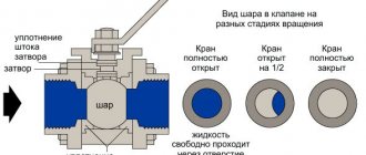
Rice. 5 Operating principle of a wedge-type valve
Valves for pipelines - types and classification
Gate units have different design and physical parameters; according to the design and classification of gate valves, they are divided into the following classes:
- According to the housing manufacturing technology:
- Welded.
- Casting is the main method of forming hulls.
- Forged or stamped - the technology is used to create high-strength cases; the parts are connected to each other by welding.
- Combined - made from forged and stamped parts by welding.
- By seal type:
- Graphite-reinforced, liquid metal.
- Stuffing box - the movable spindle or rod is separated from the working medium by a stuffing box, impregnated with oil and compressed by a union nut or a special part - an oil seal.
- Bellows - tightness is achieved through the use of corrugated elastic shells made of metal and synthetic materials.
Rice. 6 Disassembling the wedge-shaped system (body, type of valve wedge)
- By type of force transmission to the valve:
- Rotary - used in manual mechanical systems, where the screw spindle moves due to the flywheel.
- Translational - the rod has a cylindrical shape and moves by transmitting force to it hydraulically or electrically.
- By drive type:
- Manual - a flywheel and a threaded spindle are used to transmit force.
- Electric - the valve is controlled by a moving spindle, which is the armature of the electric coil.
- Hydraulic - hydraulic fluid exerts pressure on a movable rod with a valve placed in a sealed cylinder.
- Pneumatic - the spindle moves due to the pressure of compressed air on its surface.
Rice. 7 Drives
- According to the design of the valve assembly:
- Wedges. The shutter is wedge-shaped and, when lowered, is located between two inclined seat surfaces.
- Parallel (single or double disc, gate). The gate element is made in the form of a flat disk or gate, which locks the channel, descending into small profile recesses in the body.
- Hose. When the system operates, the shutter mechanism compresses the elastic rubber hose, thereby blocking the channel of movement of the substance.
- Rotary. A shut-off element in the form of a disk is located in the pipe channel on its center line; during operation, it rotates around the central axis and blocks the flow of the passing substance.
Using a pop-up rod
Such equipment allows you to fully control the position of the shutter already on the extended rod during its rotation. The movement occurs according to the principle of a jack with a rotating steering wheel. The movement of the rod will be directed upward, pulling the shutter along with it, which will pass along the plate inside the body into the space under the cover. When opening, the rotation is to the left.
When closing, movements should occur clockwise (to the right). The seal will be pressed with the help of a cover that rests on the sleeve threaded into the rod. When the nuts are tightened, the cover will rest against the lower part of the bushing, which will press the stem seal.
Wedge valves
This type of valve device is a valve with angled surfaces, which, when released, is located in a wedge-shaped seat.
Hard wedge
The model is characterized by its low cost, simplicity, rigidity, reliability and good tightness parameters; during manufacture it requires the use of high-precision equipment. The wedge is hinged to a spindle located in the top cover and lowers into the channel along guides built into the body; the system is capable of working with large pressure drops. Disadvantages include difficult repairs and jamming when exposed to high temperatures as a result of linear expansion of the metal when heated.
Fig.8 Wedge valves for pipelines - design
Wedge with two discs
Wedge valves for pipelines of this type consist of a valve in the form of two disks placed at an angle with an expanding part between them (looks like a spherical fungus) - this allows it to self-align, while ensuring a high density of channel closure and eliminating jamming.
Types of valves with two disks have a complex design and are therefore expensive; their advantages are low wear of the valve and seat surfaces due to the lack of contact along the path of movement, a high degree of sealing, and a small applied force to close the passage.
Use of rods
Telescopic rods are needed for servicing and starting valves located near the ground. They are designed for closing and opening gates and valves when using well-free installation technology. Thanks largely to the technology used, the device quickly adapts to the depth of the pipes and begins to push in and out the shaft and rod body.
The inner part of the rod is made of galvanized steel, and all other elements are made of polyethylene. Standard adjustment keys will be sufficient to work with the cone adapter. A device is needed, first of all, to regulate shut-off valves, which are installed below ground level and if the exact distance between the surface of the earth and the top of the valve cannot be determined. In this case, adjustment is carried out using an extended rod immediately after its installation.
How the device works
The valve consists of a number of parts:
- guide disc;
- lid;
- oil seal assembly;
- steering wheel;
- stock;
- gate;
- frame.
The principle of its operation can be compared to a jack. The device with the shutter moves when the steering wheel is rotated to the left. The guide discs are located on both sides of the bolt and are pressed at an angle into a special socket. They are shaped like wedges. There is a shutter between the guide discs. This results in a completely sealed structure into which the main flow does not penetrate even under conditions of high speed or high pressure in the working area. Based on the method of movement, the wedge valve can be with a non-retractable or a retractable rod.
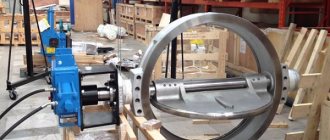
Rotary
A device of this type is called a butterfly valve; during operation, the disk is located in the flow of matter and moves in its direction. Discs are used in systems with pipeline diameters up to 1200 mm. at ambient temperatures from -200 to +450 C. and pressure up to 600 bar. The device has a simple design, small size and weight, seals the sealed channel well, and is easy to repair. Disadvantages include high flow resistance, operation only in one direction, and the inability to use in environments with high viscosity and contamination.
Dimensions
| DN | PN | L | N | V | D | D1 | D2 | nx0d | Torque (HM) | Weight, kg |
| 50 | 16 | 180 | 245 | 160 | 125×125 | 125 | 102 | 4×18 | 56,0 | 11,5 |
| 80 | 16 | 210 | 310 | 200 | 150×150 | 160 | 133 | 4×18 | 70 | 19 |
| 100 | 16 | 230 | 380 | 200 | 215 | 180 | 158 | 8×18 | 70 | 30,5 |
| 125 | 16 | 255 | 430 | 240 | 245 | 210 | 184 | 8×18 | 90 | 42 |
| 150 | 16 | 280 | 500 | 240 | 280 | 240 | 212 | 8×22 | 90 | 58 |
| 200 | 16 | 330 | 650 | 280 | 335 | 295 | 268 | 8×22 | 144 | 99 |
Parallel (gate)
In gate valve devices, the surfaces of the seats and the gate disk are parallel; when lowered, the disk (gate) seals the passage due to the pressure of the conductive medium on its surface. The disadvantages include high energy consumption for movement as a result of friction of the sealing rings of the seat and gate along the entire path of movement and, accordingly, increased abrasion of the sealing surfaces. Used with reduced requirements for tightness, easy to maintain and repair.
Fig. 10 Parallel gate valves
Hose
When transporting aggressive chemical media in the system, valves must have high corrosion protection - the best option in this case is to use hose-type devices. The unit has a working channel in the form of an elastic flexible hose, which, when the flow is blocked, is compressed in the middle part.
Rice. 11 Hose type valve - operating principle
Non-retractable stem
The steering wheel must be rotated clockwise to open the shutter. In this way, the length of the rod is reduced by removing the screw part inside the system. If you use a similar model, you can accurately determine the location of the shutter as the flywheel rotates.
It is recommended to check the number (calculate) the number of revolutions from the “open” to “closed” positions before installing the equipment. This will make further use more convenient. The operating principle of this type of valve resembles the operation of a puller. The equipment is screwed into the bolt, after which it begins to fit along the guides inside the housing under the cover.
Marking
The marking of sliding pipeline fittings is regulated in accordance with GOST 4666-75; it is carried out on the body or on a plate indicating the following data:
- Business name;
- pressure, temperature;
- bore diameter;
- steel grade in the case of using materials with special properties (increased corrosion, temperature resistance);
- quality mark, if available.
Rice. 12 Marking examples
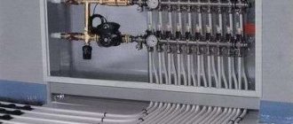
Installation of shut-off valves in water supply systems
The installation of a valve in a main industrial pipeline is carried out by qualified specialists, and the most common method is to connect the elements to each other using flanges. When carrying out work in the water main, observe the following installation features:
- Removal of water supply shut-off valves is carried out only in the absence of working fluid in the system; if necessary, the pipes at the joints are protected from dirt, scale, and limescale.
- Before installing the shut-off valves, check the quality of the flanges - the flange washer should not have cracks, scratches, gouges or other defects.
- The shut-off valves of the water supply system are placed on a strictly straight part of the pipeline and on flat areas of the earth's surface - this avoids excessive stress in places of bends and distortions that cause leaks. When installing heavy units, additional rigid supports are used.
- During operation, it is not allowed to apply excessive force to the flywheels by which the shut-off valves are activated - this can lead to breakage and cracks.
- Installation should be carried out with a soft strap, avoiding fastening to the rod or steering wheel and trying not to damage the protective coating - this leads to premature corrosion. Falls from heights and mechanical shocks are unacceptable.
Rice. 13 Methods of installation and configuration of locking devices
Before choosing shut-off valves, it is necessary to take into account its characteristics in accordance with GOST - industrial steel products have the highest parameters. Sliding units for pipelines made of non-ferrous metals are suitable for domestic use - they have small nominal diameter sizes and easy installation using threaded couplings.
Types of ventilation dampers
Modern production offers the most diverse range of valves designed for use in ventilation systems. However, the entire existing set of gate types can be grouped into several categories:
| Category | Types of valves |
| Form | Round, rectangular |
| Design | Retractable, rotating |
| Control type | Manual, electric, pneumatic, hydraulic |
| Installation method | Installation in socket, installation using flanges |
| Material | Stainless steel, alloy steel, chrome steel |
The shape of the dampers is determined by the shape of the ventilation shaft - most often round valves are used, but in some cases rectangular valves are needed:
- There is a need to hide the gate while ensuring the minimum possible use of space.
- When installing ventilation systems that use electric heaters, since they themselves are predominantly rectangular.