Individual developers independently organize water supply for their households from a well or borehole. To ensure that the water in the main does not freeze in winter or heat up in summer, it is necessary to correctly calculate to what depth the water pipe should be buried in a private house. The installation of communications in the ground depends on the climate and other factors; each of them should be taken into account when arranging the water supply system.
Section of the water supply to the house from the well.
Construction depth standards
The rules for arranging water supply systems for construction organizations are collected in SNiP 2.04.02-84 - an updated collection of standards located in SP 31.13330.2012. The document establishes the base distance for the depth of the water pipeline as 0.5 m.
This size serves as a standard used when calculating the distance of the water conduit from the surface:
- the distance from the bottom of the pipe laid in the trench to the freezing level of the soil is ≥0.5 m;
- deepening the pipeline into the soil to avoid summer heating of drinking water in the pipeline ≥0.5 m, counting from the top mark of the pipe;
- protection of communications from mechanical loads transmitted by ground transport is carried out through a minimum soil layer of 0.5 m.
The freezing interval of the ground is determined by observing the actual thickness of the permafrost layer in a cold winter with little snow. In the absence of statistical data, a thermal engineering calculation is made. They also use SNiP tables, according to which zero temperature penetrates into the soil of the northern regions by 2-3.5 m, in the middle zone - 1.2-2 m, in the southern regions - 0.5-1.2 m.
If for some reason it is not possible to dig a trench of the required size, the water supply is thermally insulated or protected from low temperatures using an electrical cable.
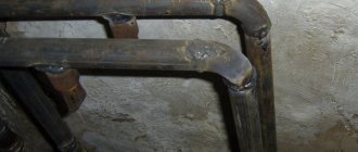
Insulation of a water pipe underground.
Possible methods of thermal insulation
Let's look at exactly how we can prevent freezing and damage to sewer pipes from exposure to low temperatures.
The following methods are distinguished:
- Lay the pipe to a depth that will retain the necessary heat and prevent it from freezing;
- Use of special heat-insulating materials;
- Using a heating electric cable.
Depth below freezing level
The first method is not suitable for those who took up the work on their own. The advantage is that if you laid the pipe below the soil freezing level, then you will not need additional insulation methods. But this is quite labor-intensive work that requires special equipment, practical knowledge and additional financial resources.
If you choose this method, then you cannot do without specialists and large investments.
Materials for thermal insulation
- Mineral wool. The classic method of insulation, but is not suitable for sewer structures, since it is not justified by the amount of material used and its price. It loses its insulating properties when exposed to moisture.
- Polyurethane foam. This option has high efficiency, low cost, and moisture resistance. It consists of cylinders that are placed like a “shell” on the insulated system. Excellent for sewerage.
- Penoizol. Liquid, highly effective thermal insulation material that creates a monolithic, impermeable shell. Requires specialist skills and special equipment to use. Therefore, it is not suitable for independent construction.
- Foamed polyethylene. A highly effective material that is easy to use and guarantees quality. It is a pipe with a cut of various diameters, which is put on the insulated area and secured at the cut site.
There are other highly advanced heat-saving materials, but they are rarely used in practice due to their high cost.
Heating electric cable
This method is divided into two options: budget and more expensive.
In the first case, an ordinary cable is used, which warms up the communication throughout its entire length. The downside is the irrational consumption of electrical energy.
In the second case, a stand-alone cable is used. It also heats the pipe, but selectively in those areas where the temperature decreases. The high price will justify the service life and save costs.
To be more economical, combine two options at once. The basic cable will be an ordinary cable, and in less heated areas a stand-alone cable.
What does depth depend on?
The level of seasonal permafrost is the main factor influencing the distance of the water main from the surface of the earth, but not the only one. Other circumstances are involved in the calculation of pipeline depth.
You should pay attention to the following factors:
- The level of location of the connecting point of the main line and the pressure water conduit from an underground source. The transition of the fluid flow from vertical to horizontal direction is carried out using a downhole adapter or through the caisson wall. Both elements of the equipment at the water intake mouth are designed to protect water from freezing.
- Location of the inlet for communication in the foundation of the house. The lower the opening is, the deeper the trench for the pipeline will be.
- Characteristics of soil along the ditch route from the source to the water supply facility. The depth of soil freezing varies depending on its condition. For areas in the middle zone, the figures are as follows: in clayey rocks - 1.3 m, sandy and loose rocks - 1.6 m, gravel - 1.7 m, hard rocky rocks - 1.9 m.
- Groundwater occurrence. When underground currents are close to the surface, the depth of the trench decreases. The amount of precipitation in a given area affects the calculations, since groundwater is fed by rain streams.
In order for the water supply system to function safely and in a stable manner, all of the above factors should be taken into account. The depth of the highway can be influenced by the use of technical means.
Protection from mechanical influences is carried out by placing pipes in steel sleeves of larger diameter and covering the water pipes on top with concrete slabs.
Microtunnelling method
Microtunneling is automated tunneling with pushing of the pipe lining structure, carried out without the presence of people in the excavation. This is a trenchless method of laying pipelines and communications using special jacking stations, when the pipe is “pushed” through the soil from one station to another using a special tunnel-boring shield, also called a drill (auger drilling) at a distance of 100-120 m, which mixes during operation rock with water and is transported by the cleaning system to the surface, where it is separated.
Microtunneling technology makes it possible to lay underground communications in densely built areas or areas crossed by transport and other communications. Work is carried out in water-saturated, non-rocky and rocky soils, including mixed mining, in coarse soils with the inclusion of gravel, pebbles, crushed stone in the form of an interlayer and boulders. The laying is carried out along a straight and curved route in profile and plan.
Behind the shield, pipes are pressed using jacks: steel, fiberglass, ceramic, concrete, reinforced concrete or polymer concrete with special fiberglass couplings that provide little resistance when pushing the pipes in the well. For the construction of sewer collectors, pipes with internal polyethylene insulation are usually used, which increases the service life of the structure by 3-5 times.
Laying is carried out using two pits: starting and receiving, the depth of which corresponds to the depth of laying. A powerful jacking station is installed in the starting pit, on which a tunneling shield is placed. Using jacks, the shield is driven into the ground to its length, after which a section of the pushing pipe of the same length is placed on the jacking station, and the process is repeated. After the pipes have been built up in separate sections, further penetration is carried out until the shield exits into the receiving pit. After this, the shield is dismantled, and the pipes remain in the ground.
By changing the standard size of the tunneling shield, it is possible to lay underground microtunnels of various internal diameters - from 250 mm to 3600 mm with a burial depth of up to 30 m. The minimum depth of the top of the pipeline relative to the ground surface should be at least 1.5-2 pipe diameters. The distance between the pipeline being laid and already located communications and structures must be at least 1 m. Shield penetration is used in semi-rocky and rocky soils, where it is impossible to use other methods, and concrete or reinforced concrete pipes are used.
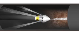
The first part of the drill string can deviate by several degrees vertically and horizontally (up to 13 mm at 200 m), which requires constant adjustment of the drilling direction. Accuracy of penetration is achieved by a computer control complex using a laser shield guidance system. The drilling process is controlled from the surface by an operator using a navigation system.
Microtunneling technology makes it possible to lay communications and pipelines using small-diameter collectors in soil of any complexity - from unstable loams and aquiferous sands to rocks, including with a mixed face, in coarse soils with the inclusion of gravel, pebbles, crushed stone in the form of an interlayer and boulders.
An advanced control system for tunnel boring complexes ensures tunneling accuracy that meets the highest requirements and allows at every moment to control values that fully characterize the position of the tunneling shield, the parameters of its movement, as well as the operating parameters of its main components and mechanisms. The complexes are built on a modular principle, which makes it possible to relocate them from one facility to another and minimize the installation time for equipment.
At what depth to bury a water pipe in a private house - how to calculate correctly
The starting point for calculations is information about the climatic conditions of the area where the land is located. You can use the freezing depth map.
Map of soil freezing in the Moscow region.
Further actions consist of considering each of the factors influencing the depth of the highway:
- The standard depth value is determined. The freezing amount taken from the map takes into account the soil structure. If other sources are used, pay attention to the nature of the soil. Loams are common rocks in the central part of the country. For the conditions of such areas, the calculated depth is 1.3 + 0.5 = 1.8 m.
- The distance of the caisson bottom from the wellhead is compared: it should not be less than the value obtained by calculations. If the condition is not met, the head structure is deepened to the norm. Another option to reduce the calculated depth is to use thermal insulation or heating of the pipeline.
- The distance from the point of passage of the highway through the foundation of the house to the earth's surface is measured. If the result does not correspond to the calculated indicator, the location of the hole is changed. If the well is located at a great distance from the house, the difference in elevations is taken into account: according to SNiP, the slope of the pipeline towards the source is ≥0.001, in practice - 0.002-0.005. The minimum difference in trench depths with a length of 100 m will be 10 cm: 1.8 m near the house, 1.9 m near the well.
Thermal calculations are complex for an untrained person. Instead of a heat insulator, it is better to use a heating cable equipped with a thermal control device, either automatically or manually. The conductor is laid when installing the pipeline along the entire length of the pipeline.
Where to start
Drawing up a layout diagram of the facility’s water supply system is the initial stage of water supply construction. The sketch depicts the location of the branches of the water pipelines on a scale, and fills out the equipment specifications - the dimensions of pipes, fittings, connecting and locking devices. The descriptive part indicates the type and thickness of rocks composing the route section and the depth of the highway. Information is necessary to complete the system with equipment, plan excavation work and carry out repairs in the future.
Practical actions:
- Level the area within the construction site and clear it of foreign objects.
- Mark the route of the pipeline sections to be laid. For the house-well route, a cord is pulled along the axis of the future trench. To prevent the twine from interfering with digging, its projection is duplicated by marking it on the ground with improvised objects, and then removed.
- Dig 2 holes with a cross section of 100x100 cm to the calculated depth. One is near the foundation, the other is at the junction of the ditch with the well head.
- Equip outlets from structures with connecting devices. To carry out the work, the installer goes down into the pit.
The next stage of construction is the choice of excavation method. They dig manually, if the volume of excavation is small, or with the help of earth-moving equipment.
Which SNiP and SP should I use?
All construction work is regulated by a set of rules (SP) and SNiP. When determining the parameters of a pit for water supply, the following documents are used:
- SNiP III-42-80;
- SNiP 2.05.06-85;
- SNiP 3.05.04-85;
- SP 34-112-97.
These documents list all the conditions for calculations, provide data on soil types, types of pipes and pipelines, and write formulas by which the optimal parameters of pits are calculated. Focusing on the norms, you will calculate everything correctly, without errors.
How to dig a trench for a water supply
To dig ditches <1 m deep, small-sized equipment is used - walk-behind tractors with mounted cutting attachments. The width of the gap for placing the pipeline ends up being 15-20 cm.
Digging a trench with an excavator with a narrow bucket.
In the layer interval of 1-2 m, a more powerful attachment to the tractor is used - a bar, which is a belt or chain mechanism with buckets reinforced with carbide teeth. Using a bar machine, a ditch with vertical walls 30 cm wide is formed in hard, frozen rocks.
Trenches for laying pipes in the soil to a depth of ≥2 m are dug using excavators with a narrow bucket : the width of the ditch is 50 cm. If the ditch is traversed manually, safety measures must be taken to prevent possible collapse of the walls.
Basic rules for constructing a ditch:
- The width of the bottom according to SNiP is ≥70 cm. In practice, the requirement is often violated: in order to reduce the volume of soil removed, the canvas is narrowed to 50 cm.
- The mass of earth extracted from the subsoil is placed at a distance of 2-3 m from the boundaries of the excavation so that the walls of the excavation do not collapse under its weight.
- The slopes of the ditch are left vertical in soils: clayey - to a depth of 1.5 m, especially dense - 2.0 m. In other cases, with such deepening, the trench walls are leveled to the natural angle of repose of the rock.
A sand and gravel cushion 15-20 cm thick is poured along the bottom of the ditch, compacted and moistened with water. Afterwards the pipes are laid and connected and a test run is done. If there are no leaks, the excavation is backfilled with previously excavated soil.
Why do you need a calculation?
Water and sewer pipes must be laid in the ground to a certain depth. This parameter is regulated by SNiP, SP, and must be strictly observed .
If you incorrectly calculate the depth of the trench, during operation of the water supply system it may freeze and be damaged. The width of the trench also matters, since you need to lay a pipe in it and provide a layer of insulation.
During construction, you also need to know the area to determine the volume of excavation work.
Advantages of HDPE compared to metal pipes, affecting the depth of their installation
Water pipes are made of metal and plastic. The first group includes steel products - they were installed in buildings of the last century, and galvanized ones, which are not used for drinking systems: the quality of the water is lost. Plastic pipes include thick-walled hoses made of low-density polyethylene - HDPE.
When installing water supply for individual houses, HDPE pipes are mainly used.
Polyethylene sleeve 350 mm coil.
They have advantages in terms of installation depth compared to metal lines:
- The thermal conductivity of plastic is 0.3 W/mºC, for steel it is 47. The ability to retain heat in HDPE is 150 times higher, which makes it possible to reduce the depth of laying the water supply. The amount of proximity of the hose to the surface is calculated according to the methodology set out in SNiP.
- Plasticity of HDPE pipes with high strength. The permitted pressure for the shell is 1 MPa (10 atm). In the event of an abnormally frosty winter, the ice plug will stretch the polyethylene without compromising the integrity of the water supply. Freezing water will break a steel pipe.
HDPE pipes are supplied in coils that can accommodate 100, 150, 200 m of hose. This allows for the installation of long sections of water pipelines without joints in the underground part. You will need 2 connections: to the well pump hose and to the water supply system distributor installed in the house. Other advantages include the corrosion resistance and flexibility of HDPE. The latter quality allows you to change the direction of the line without the use of fittings.
Connection diagram
Installation of plastic pipes begins with choosing their connection diagram. Depending on the location of the work, you should first draw a schematic representation of the location of pipes and plumbing connection points on a separate sheet.
If the circuit includes a water heater, boiler or indirect heating boiler, be sure to study in detail the connection diagram that comes with the equipment.
Based on this diagram, the further layout of the pipes is calculated. If you are planning to replace old metal pipes with new ones, then analyze how the pipes were laid before. If you don’t find any obvious errors in the diagram and the pipes don’t bother you, then you don’t need to draw up a new plan - draw the old diagram on paper with all the dimensions.
Distance between two pipes underground
Building codes prohibit the placement of water and domestic sewage pipelines in the same trench. Laying HDPE pipes in different ditches is permitted if the distance between them is ≥1.5 m.
If the intersection of two communications cannot be avoided, the water supply is located ≥20 cm above the sewer pipe.
Minimum distances of water pipelines to other communications and structures:
- 2 m - high pressure gas pipeline;
- 1.5 m - heating mains and drainage and storm sewerage;
- 1 m - low and medium pressure gas pipelines;
- 50 cm - low-voltage power cables used for communication, in accordance with the PUE.
If the cable line is insulated with a plastic pipe, it can be laid in the same trench with the water supply, but ≥25 cm above it. In this case, the voltage transmitted through the cable is <35 kV. The intersections of communications are protected by cases made of steel and concrete; their slopes must be one-sided.
Sewer level
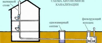
Slightly different rules apply when deciding how deep to bury a sewer pipe in a private house. This system works differently: wastewater is either drained into the septic tank by gravity due to the slope, or is pumped by a pump, so it does not linger in the pipes and there is nothing to freeze in them.
Scheme of an autonomous sewerage system Source www.alta-sib.ru