Valves are one of the most important elements in a pipeline. Their operating principle is based on blocking the flow of gaseous and liquid media by changing the flow area in systems constructed from pipes with a diameter of 50 - 2000 mm, operating at a operating pressure range from 4 to 200 kgf/cm2, and ambient temperatures not higher than 565 ºС.
There are many varieties of valves available that have design features and are designed for operation in environments with different levels of aggressiveness and temperature conditions.
Usually, the need to install shut-off valves of one type or another is thought through at the pipeline design stage. Since the reliability and safety of the entire engineering structure directly depends on the correct choice of design, the quality of its assembly, and the product’s compliance with certain parameters and standards.
General operating principles
There are many design types of shut-off devices that ensure smooth flow closure. As for valves, their principle of operation on a pipeline is based on the perpendicular movement of the locking or regulating body relative to the axis of the flow of contents in the substance system.
Structurally, the valve is a one-piece cast or welded body that holds a certain part of the working medium in the internal cavity.
To connect to the process, it is equipped with inlet and outlet pipes with ends for mounting flanges, couplings, for pin or fitting connections, as well as for welding.
Body parts are made of cast iron, various grades of steel or non-ferrous metals, and are coated on all sides with an epoxy coating to protect against corrosion.
Attention! Cast iron devices 31ch6br can be used both for locking and for regulating flow moving at a sufficiently high speed of medium flow; steel products have a locking body that can only be in the extreme positions “closed” - “open”; they are used to cut off the flow.
Inside the body there is a valve consisting of movable and fixed elements (2 annular seats), which together form the area of the flow part and a tight connection of all parts, preventing the flow of the working substance.
The moving part of the valve varies in shape depending on the modification of the valve.
Basically, the constipation organ looks like:
- wedge;
- rectangular plate (gate);
- disk (one or two).
At the moment the passage is blocked, the pressure of the medium increases, acting on one side on the valve assembly with a fairly significant force, which is then transmitted to the sealing planes of the seats and the valve.
To reduce the negative impact of this effect, a rotating shaft (spindle) is used to transmit torque from the drive or flywheel to the locking element, which is screwed at one end into the running nut fixed at the top of the locking element, and the other is rigidly connected to the flywheel.
The presence of such a system, operating on the principle of operation of the “screw” - “nut” connections, ensures the transmission of greater force and the tightness of shutting off the flow of the working medium, and also prevents spontaneous movement of the valve when the drive is turned off.
To seal the hole where the spindle extends from the housing into the external environment, a special seal is used, working on the principle of an oil seal or bellows.
To control devices with small diameters up to DN 200 mm, a flywheel is used; in products with large nominal bores, the spindle needs to make a lot of turns before the valve rises and lowers.
It is difficult to do this manually, so gear drives or hydraulic drives are used for such products. If remote control is required, the valves are equipped with electric drives.
The permissible amount of medium leakage when the valve is closed must comply with the standards established by GOST 9544-75.
Specifications
The main dimensional and physical parameters of valves are regulated by GOST 9698-86, according to this document:
- They are produced from steel, cast iron, non-ferrous metals and alloys (mainly brass).
- Dimensions are specified by the nominal diameter DN, which is approximately equal to the internal diameter. The values of Dn are fixed and are generally subject, with some exceptions, to the standard digital series.
- All types of steel valves are designed for operation in the temperature range from - 60 to + 565 ° C with a supply pressure of 1.6 to 250 bar.
- The nominal diameter of steel products depends on their pressure parameters and ranges from 15 to 1600 mm.
- The main types of connection to the pipeline of steel fittings: coupling (threaded), flanged and welded.
- The operating temperature range of cast iron valves is from - 15 to + 300 °C and from - 40 to + 300 °C for products with pressure parameters of 16 and 25 bar. The pressure withstandable by all models ranges from 1.6 to 25 bar.
- Conditional diameter of cast iron products is from 40 to 2000 mm.
- Cast iron fittings are installed in the pipeline only using flanges.
- For valves made of non-ferrous metals and their alloys, the nominal pressure ranges from 16 to 40 bar, their nominal diameters range from 15 to 300 mm.
- It is permissible to operate brass products at temperatures of the transported medium not exceeding + 200 °C.
- Methods for connecting brass valves to the pipeline - flange, coupling (threaded) and welding.
Wedge valve operation
Wedge devices include devices that have a movable shutter part in the form of a plate tapering towards the end, which is why they are called “wedge”.
Attention! The functional purpose of a wedge valve is to completely shut off the flow of working material; to regulate flow, the product is used in exceptional cases.
In such devices, the sealing surfaces on the seats are located parallel to the material of the sealing elements on the valve body and form a certain angle to the axis along which the wedge moves.
The operating principle is based on closing the passage opening by raising and lowering the shut-off element in a perpendicular direction to the moving working material.
The bolt is raised by screwing onto the spindle - a special axis with a long thread at the end, forming a threaded pair with a nut secured to the bolt element. The spindle, when receiving torque from a manual or electric drive, begins to perform movements of a rotational, rotational-translational or translational nature and carries the wedge with it.
For more information about the design and operating principle of a water wedge valve, watch the video.
Varieties of wedge design
The operating principle of wedge valves also depends on the type of valve.
It can be produced in the form of:
- A rigid plate tapering towards the bottom. In this case, the wedge is a single piece, the principle of which is to smoothly lower into the lower part of the body, while being perpendicular to the axis of the pipeline. The wedge fits tightly to the two side saddles and interrupts the movement of the working substance. This design has a number of disadvantages, among them are:
1. danger of jamming; 2. difficulties in lifting the wedge as a result of sudden changes in temperature of the working substance; 3. difficult fit to saddles. - A double-disk wedge consisting of two elements movably fastened together at an angle to each other. The double-disc wedge valve is a more advanced design than the rigid wedge.
Its operating principle is as follows: when closing the valve, the disks rotate relative to each other and are pressed tightly against the seats; when opening, the disks move away from the seats and clear the holes for the passage of the working substance. It ensures high tightness of the shut-off body, reduces the risk of jamming, and requires less effort to closing. Its sealing surfaces are less subject to wear. - Elastic locking organ. Structurally similar to a double-disk wedge, with one difference - its disks are connected to each other using an elastic element. The advantages of its operating principle are the ability to bend under the pressure of the working medium and provide a tighter relationship with the planes of the sealing material when closing the valve. Closing devices with a rubberized wedge They have low operating torque and a smooth full passage, so there is no strong friction and high wear on the locking elements.
Control methods
Opening and closing is performed by a handwheel or drive.
Controlling a steering or segment steering wheel is also called manual control, since no mechanisms are needed for adjustment - it is enough to apply physical force of a person (unscrew or tighten).
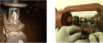
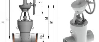
Rice. 5 Gate valve without actuator
In the basic configuration, the valves are sold without drives - they can be purchased separately to automate the system.
For ease of operation, valve control is often automated in practice. This is done using mechanical or more complex types - pneumatic and electric - drives.
Pneumatics are installed on valves with a large remote control, and electric drives can shut off flows on any valves, including the smallest ones.
Advantages and disadvantages of wedge devices
The advantages of wedge valves include providing an increased level of tightness of the flow area in the closed position, a simple operating principle, as well as a small amount of force required to connect the parts of the shut-off assembly with the maximum possible seal.
This is facilitated by the formation of an almost right angle between the directions of the drive force vector and the force vector acting on the plane of the sealing surface of the valve element. As a result, even a small force passing through the spindle can have a significant impact on the contacting surfaces of the seals.
The disadvantages of devices with this operating principle are:
- the need to equip the body cavity with guides for centering the wedge;
- rapid wear of seals on the valve;
- the complexity of the technology for obtaining tightness in the closing element.
Retractable and non-retractable stem models
When choosing a modification of a wedge valve for certain operating conditions, the location and operating principle of the travel unit are of great importance. Depending on whether it is located inside the housing or outside its cavity, devices are divided into products with a retractable and non-retractable rod.
General technical specifications
| Name | DN, mm | PN, MPa | Temperature range of the transported substance | Working environment |
| With non-retractable stem | 40 — 500 | 1,6 | From -15ºС to +130ºС | Hot and cold water, non-aggressive environments |
| With retractable stem | 15 — 1200 | 1,6 — 10,0 | From -70ºС to +450ºС | Hot and cold water, substances with any degree of aggressiveness, oil products, gas |
Design and principle of operation of shut-off valves with a retractable rod
In valves with a retractable stem, the threaded part of the spindle and the running nut are extended beyond the boundaries of the body parts. At the other end it is rigidly connected to the closing part.
The flywheel, rotating through a threaded nut, moves the rod, which in turn causes the bolt to move forward.
In this case, the upper end of the spindle moves out of the body by the amount of stroke of the bolt element. Thanks to this principle of operation of the running gear, the transported substance does not have a negative effect on the threaded pair, and the stuffing box seal is less susceptible to wear.
Attention! When placing a parallel valve with a rising stem, it is necessary to provide a free space of at least the diameter of the passage hole for the spindle exit above the cover seal.
Design and principle of operation of shut-off valves with a non-retractable rod
In these models, the threaded end of the rod is rigidly fixed to the flywheel, and the running nut is attached to the valve inside the body. When the spindle rotates, the nut is screwed onto the end of the spindle, as a result of which the movable part of the shutter begins to move.
The running mechanism of such valves is located in the working environment and therefore can be damaged by abrasive particles contained in the transported substance or quickly corrode.
These shortcomings impose restrictions on the operation of products in oil pipelines, systems transporting sea water, and chemically aggressive compounds.
Properties
A metal such as steel can be easily machined, as a result of which they are more ductile and at the same time stronger than cast iron. For the manufacture of shut-off valves, steel is used, which is an iron alloy with a low percentage of carbon in its composition.
Fig.2 Products with a nominal diameter (DN) of 250 mm.
One of the key properties is resistance to high temperature conditions.
However, these designs also have disadvantages. This is susceptible to corrosion. Therefore, they are either used in systems with the least aggressive working environment, which contributes to the formation of rust to a lesser extent), or choose a stainless steel grade that can be used even in an aggressive working environment.
General properties, for steel models:
- hydraulic resistance in open passage conditions;
- no turns in the flow of the transported substance;
- possibility of operation in conditions of transportation of high-viscosity medium flows;
- ease of daily maintenance and repair;
- relatively small dimensions;
- the possibility of the working medium entering in any direction.
However, there are also nuances of their use, which can also be attributed to properties:
- impossibility of use in highways where the working medium is a substance with crystallizing inclusions;
- relatively small permissible pressure drop across the gate (if compared with a valve);
- low shutter speed;
- risks of water hammer at the end of the stroke;
- large height required to unscrew the spindle;
- difficulties in repairing the sealing surfaces of the valve during use.
But despite this, they remain one of the most widely used types of shut-off valves.
Electric models
A gate valve equipped with an electric drive is one of the more modern shut-off devices, which are successfully used for work in process pipelines for industrial purposes and in housing and communal services. The electric drive is responsible for the timely closing and opening of the lock, holding it in an intermediate position if required by technology, and also automatically shuts off the valve in the event of an emergency. The electric drive control unit is mounted either on the unit body, or mounted in a special cabinet, on racks, or located in a remote location.
For details about the design and operation of the electric drive on the valve using the example of the URPS BEERS 13. NL series, see the video.
Design and principle of operation of an electrical apparatus
The drive mechanism is connected to the valve spindle using a special bushing and consists of an electric motor and gearbox.
The principle of its operation is as follows: when control signals are received, the engine acts through a transmission mechanism on the spindle, which in turn opens/closes the shutter or places it in an intermediate position.
Modern electric drives also include limit switches and a torque limiting clutch. They turn off the power to the electric motor when the bolt element reaches its extreme positions or when a force acting on the rod occurs above the set value.
The ability to limit torque when the valve is jammed or clogged helps prevent failure of the valve and actuator.
Thanks to this operating principle, on large highways it is possible to create a single control point for all valves equipped with an electric drive.
This method of controlling the shut-off body is very effective because it is reliable and has a long service life.
Attention! To shut down in the event of a malfunction of the electric drive or other emergency situations, the valve is equipped with a manual override - a flywheel.
Types by connection type
There are two methods of connecting shut-off valves to a pipeline:
- flange connection;
- welding.
Weld valves
Modern welding technologies ensure maximum tightness and strength of the connection. However, as a rule, welded products are made of steel. Welded cast iron valves are very rare, because... Cast iron belongs to the category of difficult-to-weld metals. During the welding process, any deviation from the technology leads to cracking of the cast iron seam.
Flanged valves
Flange connection is the most common type of joint of pipeline elements.
Flange models are equipped with:
- a flat end connection (flange), made in the shape of a circle, square or rectangle, through which the connection to the pipeline is made;
- rubber or fluoroplastic sealing rings (gaskets) that ensure the tightness of the connection;
- plugs (obturators), with the help of which the pipeline is blocked for repairs.
The advantages of a flange connection include easier installation of shut-off valves in hard-to-reach places and quick disassembly during dismantling.
Gate valve operation
Gate valves have the ability to pass large volumes of working materials, as well as carry out filtration, grinding of impurities passing through them and dosing useful components.
Based on these capabilities and the peculiarities of the operating principle of the units included in their design, the products are widely used in sewerage drainage systems, in process pipelines of chemical, oil and gas production, construction, pulp and paper, and mining industries.
Gate valves of the ZMS type are used to shut off pressure lines in fountain, wellhead and injection type equipment, and manifolds of drilling rigs.
Attention! Gate valves are always installed in a vertical position, so that the knife plates are perpendicular to the flow of work.
Design and principle of operation of gate-type fittings
A metal gate is a plate or a sharp polished and sharpened plate shaped like a knife or guillotine. Its sharp ends are equipped with strong seals (metal or synthetic), which increase the wear resistance of the main working part, especially when operating in aggressive environments with a large number of large granules and impurities.
In the production of seals, synthetic materials are used that are resistant to chemical influences and temperature changes:
- nitrile rubber;
- ethylene propylene diene rubber;
- elastomers for hot environments;
- silicone rubber.
Gate valves have a simple and at the same time reliable operating principle.
It consists of transferring force from the action of a manual, automated or mechanical control mechanism to a rod or spindle, which in turn drives the gate element to completely or partially block the passage hole.
The operating principle of a gate valve is clearly shown in the video.
In this case, the spindle can have a retractable or non-retractable design. The tightness of the retractable rod is ensured by a seal made of synthetic cotton fibers, graphite, etc.
Working Environments
Each model has its own working environment that meets technological standards. However, if we describe in general the conditions in which environment they can be used, then in a generalized form their list looks like this:
- water;
- steam;
- oil;
- oil;
- natural gas;
- liquid non-aggressive petroleum products;
- non-aggressive liquid and gaseous media.
By the way, such a working environment, like water, requires clarification. Some are designed for use at critical temperatures, for example in heating systems, while others are not.