To design new and repair existing pipeline systems, state standards regulating shut-off valves are used. The development and production of all types of valves for pipelines is carried out on the basis of these standards, which unify all dimensional values of equipment. Modern manufacturers who manufacture their products based on their internal technical specifications use the same standards as those specified in GOST.
What does the nominal diameter of a valve DN mean?
To designate and classify valves of all types in modern technical documentation, it is customary to use the designation DN - nominal diameter. This designation applies to the designation of the internal diameter of the working passage of the device body. This designation of the nominal diameter is, in addition, common to the designation of other elements of the valve design that are included in the size group.
The nominal size allows you to quickly select the desired standard size of the device for installation; in fact, this designation is also used to mark the diameter of the pipeline, which makes it possible to quickly select the range of fittings for the pipeline without going into detail. The use of the nominal size of the internal working passage DN or DU is regulated by state standards and is the official type of marking of fittings by its diameter.
Service life and installation
On average, the service life of valves ranges from 30 to 50 years and depends on:
- compliance of the installed equipment, sealing gaskets and mounting fasteners with the technical characteristics of the pipeline and the working environment;
- installation locations. Installation of fittings must be carried out in places accessible for inspection and maintenance;
- compliance of commissioning works with established standards.
Rules and stages of installation of shut-off equipment:
- Shutting off and preserving the pipeline in the area where the equipment is planned to be installed.
- Pre-installation re-preservation of valves.
- Cleaning of valve flanges and pipelines from preservative lubricants, impurities, dirt, sand, scale and rust along the entire contact length.
- Gasket between the flanges of the sealing elements and their uniform pressing.
- Alignment and fixation of flanges diagonally using bolts. Warping or tension that deforms their structure is not allowed.
- The flywheel should only be positioned in the “up” or “sideways” position.
- Checking joints for leaks. If necessary, additional sealing is required. Pressure testing is carried out exclusively in the “open” or “closed” positions.
Important. Hanging of large-sized units is carried out only by the pipes, because other elements (flywheel, electric drive, etc.) may be damaged when suspended.
What determines the diameters of valves?
The use of valves of different diameters as shut-off valves is most often caused by the technical conditions for each specific type of pipeline and the conditions of the products transported through it. The diameters of the valves are determined by the internal diameter of the device cavity. This feature of marking and sizing is caused by the need to provide the simplest possible way for the transported flow to pass through the pipeline.
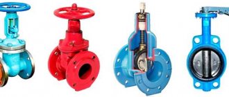
The developed state standards define the main types of shut-off valves. These types include:
- Flanged valves;
- Steel valves;
- Cast iron valves;
- Gate valve types;
- Wedge types of valves.
For each type of fittings, norms and standards have been developed that determine not only the internal diameter of the holes, but also the types of connections and the dimensions of the flange elements. The following standards are used for classification:
- GOST 3706-93 - standard for the production of flanged types of valves;
- GOST 9698-86 - defines the standard for two types of fittings for steel and cast iron valves;
- GOST 10738-76 - used to classify wedge-shaped types of shut-off valves;
- GOST R 55020-2012 - classifies gate structures.
Prices for 30h6br
| DU | RU | RUSSIA (KAZ) |
| Price including VAT RETAIL | ||
| 30ch6br Du50 | 16 | RUB 1,662 |
| 30ch6br Du80 | 16 | RUB 2,682 |
| 30ch6br Du100 | 16 | RUB 3,832 |
| 30ch6br Du125 | 16 | Great Dane |
| 30ch6br Du150 | 16 | RUB 9,113 |
| 30ch6br Du200 | 10 | RUB 16,674 |
| 30ch6br Du200 | 16 | RUB 23,666 |
| 30ch6br Du250 | 10 | RUB 23,666 |
| 30ch6br Du300 | 10 | RUB 35,734 |
| 30ch6br DN400 | 10 | RUR 76,252 |
Typical sizes of flanged valves
Flanged types of shut-off valves, most often used for installation in pipelines for various purposes, are used as a device for regulating the flow of the working medium and locking it. Fastening to the system is carried out using flanges, a bolted connection type.
The diameter dimensions of this type of device depend on:
- From the size of the nominal diameter of the housing;
- Maximum and working pressure inside the pipeline;
- Device lengths.
The diameter of the working passage of the device body has the following values:
- Small diameter 10, 25, 80 mm;
- Medium group of dimensional values 125, 250, 350 mm working passage;
- Large sizes - 500, 600, 700, 800, 1200, 1600, 2000 mm.
Flange types of devices are used in systems whose internal pressure is nominally maintained within the range of 400-40000 kPa.
The diameter of the devices is directly related to their linear dimensions, or otherwise the construction length - 140,180, 230, 290, 330, 390, 430, 470, 510, 550 mm
Attention! The marking of shut-off valves has an alphanumeric encoding, in which the first digit is the type of device, the second digit separated by a hyphen is the diameter of the nominal diameter in the body, and the third indicates the operating pressure. The second part of the marking indicates the state standard according to which the model’s design is made.
Types by location of the running gear
The valve running module can be:
- with a retractable spindle (rod).
- with a non-retractable spindle.
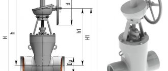
Retractable spindle
The rod on which the shutter disks are attached is located outside the body and when the flywheel rotates, it is screwed in or out of it to the height of the shutter.
The external location of the chassis allows you to monitor its condition and carry out timely maintenance. The absence of media exposure to the threads reduces wear on the running gear and packing seals.
Non-retractable spindle
The non-retractable rod is located inside the locking device body in a static position. Rotating together with the flywheel, it ensures the movement of the shutter discs along the threads. This design reduces the construction height of the products, which facilitates their use in wells, underground communications and oil wells.
The internal location of the chassis prevents access and maintenance of the device. Immersion of the undercarriage in the carrier accelerates its wear due to corrosion and exposure to abrasive particles.
The degree of wear can be reduced by operating equipment in pipelines with oil carriers (oil, mineral oils, etc.).
The models also differ in the type of seal of the running gear:
- Omental. They ensure maximum tightness through an external stuffing box in which sealing material (stuffing box packing) is placed.
- Bellows. The elastic one- or two-layer corrugated shell equipped in the external block is designed for high-cycle deformation and at the same time provides a high level of strength and tightness.
- Self-sealing. Metal, rubber and other gaskets such as rings and washers are used as a sealant. They are characterized by low wear resistance and require periodic replacement during the life of the product.
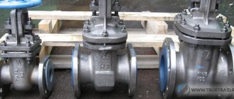
Cast iron shut-off valves
Cast iron is the material most used for the production of shut-off valves. Gray malleable cast iron makes it possible to cast housing shapes with high precision and high performance. That is why the use of cast iron valves in pipelines for various purposes is widespread.
To develop shut-off valves, standards for the dimensions of the nominal body diameter are used:
- Diameter sizes up to 100 mm - 40, 50, 80 mm;
- Dimensions of valves up to 500 mm inclusive - 125, 250, 350 and 500 mm;
- Diameter up to 1500 mm - 600, 800, 1200 mm;
- And over 1500 mm - 1600 and 2000 mm.
For cast iron products, a more stringent working pressure range has been established - 160-2500 KPa. The lower pressure threshold of valves is higher than that of flanged valves, but the upper one is lower. The dimensions of the construction length of the devices correspond to the length of flange-type valves.
The marking on the product body is the same as for other types and consists of an alphanumeric combination of encodings in the same sequence.
Gate valves
For this type of shut-off valves, the main installation location is pipelines for transporting petroleum products. The main purpose is to shut off the flow, but when used as control equipment, such devices require an additional drive.
For installation, the dimensions of the working passage of the housing with diameter are used:
- Up to 150 mm - 100 and 150 mm;
- From 150 to 500 mm - 200, 250, 300, 350, 400 and 500 mm;
- From 500 to 1000 mm - 600, 700, 800 and 1000 mm;
- Over 1000 - 1050 and 1200 mm.
To calculate the operating pressure of the pipeline, the following indicators are used: 1.6 - 12.5 MPa
Marking of the gate valve series includes:
- Method of installing a valve in a pipeline;
- Control drive type;
- Seismic resistance class of the device;
- Compliance with climatic version;
- The standard according to which the production is carried out.
Manufacturer's Warranty
- The warranty period is 12 months from the date of commissioning, but not more than 18 months from the date of manufacture.
- Warranty operating time is 400 cycles within the warranty period.
- Replacement of low-quality products - within 1 month from the date of receipt of the complaint.
Attention: During acceptance tests and in case of detection of hidden defects, it is prohibited to disassemble and repair the product by the customer without the written permission of the manufacturer. Otherwise, the product is not subject to warranty exchange and is removed from the warranty.
Wedge types of shut-off valves
The wedge type of the working body ensures simple and at the same time effective closing of the working passage. This property allows the valve to be widely used in pipelines for various purposes, from conventional water supply systems to systems for transporting aggressive substances.
Rubber-lined types of wedge valves are used in bodies made of cast iron, steel or special alloys. The connection can be either flanged or wafer; for devices with a rubberized wedge, the welding installation method is not used.
For installation, the following dimensions are used for the working passage of the cast iron body:
- 150 mm - 50, 65, 80, 100 mm;
- From 150 to 500 mm - 125, 150, 200, 250, 300, 350, 400 and 500 mm;
- Up to 1000 mm - 600 mm;
- For steel wedge valve bodies, the following working passage diameters are used:
- Up to 150 mm - 50, 65, 80, 100 mm;
- From 150 to 500 mm - 125, 150, 200, 250, 300, 350, 400 and 500 mm;
- Up to 1000 mm - 600 mm;
- Over 1000 mm - 1600 mm.
When using an electric drive, wedge valves mainly use a working passage diameter of up to 600 mm. Some manufacturers limit the series of wedge valves to a working passage diameter of 500 mm.
Types by material and manufacturing method
Gate valves are made of cast iron, stainless and carbon steel and non-ferrous metal alloys by casting, welding, stamping or forging. Combined technology combining forging, stamping and finally welding is widespread.
- Casting is used for the production of cast iron, steel and aluminum units.
- Gate valve bodies are made of steel and titanium alloys using the method of welding stamped blanks.
Welding technologies make it possible to achieve a very high strength class of products that have found their application even in nuclear energy.
Sealing elements are manufactured:
- in the form of rings made of brass, fluorine-containing polymers (fluoroplastics), polyurethane or rubber;
- with surfacing on the breech part of hard steel, resistant to corrosion (metal-to-metal technology);
- by plasma spraying of elastomer and epoxy resins or laser hardening.
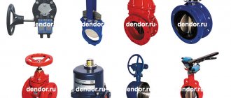
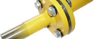
Types of valve connections
The presence in the range of valves of several size groups provides the possibility of using several types of connections between fittings and pipelines.
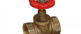
Almost all types of valves that have small diameter devices in their assortment use a coupling type of connection. Diameter up to 100 mm ensures reliable coupling connection with the pipe. The only exception here is gate types of fittings, which were designed to reduce the size of the body.
Medium sizes up to 500 mm have both standard flange mounting types in a molded case, and the possibility of installation in a wafer version. A small working passage allows the use of both mounting options. Like bolting on flanges, the use of tightening pins is equally effective for all types of valves.
Large diameter fittings are traditionally used only in flanged installations. It makes no difference how the body is made by casting iron or by welding stamped fragments. For pipelines with a diameter of over 500 mm, a flange connection using bolts provides the simplest and tightest connection possible.
Installation
Check the operation of the valve:
install an electric drive on the valve, adjust the torque limiting clutch in accordance with the value specified in this passport;
perform two complete OPEN-CLOSE cycles, in which case the electric drive must be turned off:
1) in the lower position – from the activation of the torque limiting clutch switch;
2) in the upper position - from the actuation of the limit switch when the spindle collar does not reach the stop at the upper seal from 7 to 16 mm - depending on the standard size of the valve.
In case of premature operation of the torque limiting clutch, the operation of setting its switches should be repeated.
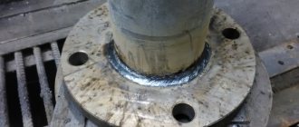
INSTALLATION PROCEDURE
The valve must be installed on a concrete foundation that prevents its weight from affecting the pipeline.
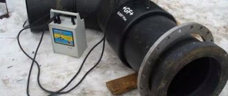
The installation position of the valve on the pipeline is vertical, with the electric drive upwards, with a permissible deviation of up to 3 degrees. The position of the wedge when welding the valve is CLOSED. Weld the nozzles (matching flanges) of the valve to the pipeline and control the weld in accordance with the rules in force at the facility under construction (VSN 012-88 “Construction of main and field pipelines”, RD 153-006-02 “Instructions for welding technology during construction and overhaul of main oil pipelines").
When installing the valve on a pipeline, the nozzles (or mating flanges) must be installed without distortions, and the holes for fasteners must coincide with the holes on the valve flanges.
IT IS PROHIBITED TO ELIMINATE DISRUPTIONS IN THE PIPELINE DUE TO TENSION (DEFORMATION) OF THE VALVE PIPE.
Install the electric drive.
Perform two complete OPEN-CLOSED cycles with the electric drive disconnected in extreme positions from the operation of the switches.
When hydrotesting a pipeline with a pressure equal to 1.5 PN, the valve must be in a fully open or intermediate position (from 25 to 75%), which will ensure the flow of the test medium into the internal cavities of the valve body.
Use an air plug to remove air.