Most pipelines for various purposes are installed by welding, which ensures reliability and long service life of the joints. But when, due to installation conditions, this method is unacceptable or periodic disassembly is required during operation, a flange connection is used. In terms of reliability and durability, it is not inferior to the welded version, and is easier to install.
Purpose and scope
Flange connections can be installed on pipelines with a diameter greater than 32 mm. In this way, branched systems are installed at industrial and chemical enterprises, in the gas and oil industries, and housing and communal services distribution networks. This type of connection is rarely used for laying intra-house pipelines.
Flange joints are needed in order to:
- connect pipes to each other or to equipment made of dissimilar materials;
- install shut-off and control valves;
- clean pipelines;
- embed measuring instruments;
- cut off a section of pipe for repair.
Marks on parts with left-hand threads
Marks are applied to all parts with left-hand threads, including parts used in machine repairs. It is not necessary to apply marks on parts with external left-hand threads, in which the direction of cutting is easily distinguishable when assembled, and on parts with left-hand threads that are not subject to disassembly.
Marking methods:
- On nuts and bolt heads that have edges, marks are applied in the form of a circular slot at the corners of the edges.
- On nuts that do not have edges, on other parts with internal threads, marks are applied in the form of a slot along the diameter at the end.
- On bolts that do not have edges, as well as on other parts with external threads, marks are applied in the form of an annular groove or a slot along the diameter at one of the ends of the part.
- Marks for metal screws are applied in the form of slots parallel to the groove for the screwdriver.
- On screws with a hexagonal or other recess for a key in the head, marks are applied in the form of a slot along the diameter at the end.
Parts to which the indicated methods of marking cannot be applied may be branded with the letter L. The marks of parts with left-hand threads must be clearly visible when disassembling the unit. The marks must not reduce the strength of the parts and must be different from the structural elements of the parts. The dimensions of the mark are established by the drawing.
What does a flange connection consist of?
A kit for one joint consists of two identical flanges with central holes corresponding to the diameters of the pipes, a gasket, a set of bolts or studs with nuts and washers. If it is necessary to protect the pipeline from stray currents, insulating sleeves are put on the bolts, and the gasket is installed from a dielectric material. If the pressure in the pipeline does not exceed 2.5 MPa, the flanges are bolted together. The studs distribute the tightening force more evenly and are more convenient for working in inconvenient places. Flange connections with studs are used at pressures up to 4 MPa.
Flange connection design
A bolt isn't really a bolt
A bolt in a connection is not a bolt - it's a spring! Tightening the flanges is where you tighten or loosen the spring. Figures No. 1 show how a spring can be considered to support a bolt tightening the flanges.
Figure No. 1. Forces acting on the “bolt-spring”
The bolt is called a “spring bolt”.
The bolt-spring force must bring the flanges closer together than the forces acting to push them apart. If the bolt spring is too loose, the pressure stretches the bolt, causing the flange to open and leak. To prevent flange separation, the bolts are preloaded (tensioned). Bolt torque values are calculated to obtain a bolt stretched to at least 65% of its yield strength.
The yield strength is the stress at which the bolt shank begins to stretch (the limit is the moment at which it breaks).
What is a flange and what types are there?
In most cases, flanges are ring-shaped plates of steel, but sometimes they are made in the form of a square or rectangle. The end of the pipe is inserted into the central large hole, and bolts or studs are inserted into the holes evenly distributed along the outer perimeter. The list of flange types includes feedthroughs and plugs. The first are intended for joining pipeline elements, the second close dead ends or cut off sections being repaired or replaced.
To ensure that products made in different countries are interchangeable, a unified classification of flanges has been developed. In Russia this is GOST, European countries use the German DIN standard, and America, Japan and Australia use ANSI/ASME. However, often the same flanges are indicated by different symbols. Therefore, standards are translated using special tables.
The performance standards are indicated in GOST 12815-80 in numbers from 1 to 9:
- With a connecting protrusion in the form of a chamfer at an angle of 45⁰.
- Same as 1, but the protrusion is at a right angle.
- With a groove on the inside and a projection at an angle of 45⁰ on the outside.
- With a spike.
- With internal annular groove.
- With a chamfer for the lens gasket (vibration insert) on the inside.
- Sample for oval gasket.
- With spike for fluoroplastic gasket.
- Same as 8, but instead of a tenon there is a groove.
Types of flanges
When installing pipelines, several types of flanges are used:
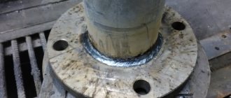
- The collar ones are designed for a pressure of 0.1 - 20 MPa at a temperature of -200 - +600⁰ The protrusion in the central part (collar) is butt welded to the pipe with one seam.
- Flat ones hold pressure up to 2.5 MPa at temperatures -70 - +300⁰. They are put on the ends and secured with two welds.
- Hardware for connecting equipment or devices;
- Threaded versions are screwed onto the ends.
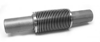
- Freely rotating ones consist of a plate and a ring, which is welded to the end, and the flange rotates freely on it. This flange connection is installed in hard-to-reach places or where frequent preventive measures are required on the pipeline. Designed for pressure up to 2.5 MPa.
- Ring options for plugs are made without a central hole.
Calculation of tightening modes for flange studs and nuts
Calculation of stud tightening modes. The one-time mode of tightening the studs is a special case of the single-pass group tightening mode, in which the number of groups of studs is n=1, i.e. All flange studs are loaded simultaneously. In the single-pass mode of tightening the studs, the current loading force of the next group of studs (RD26-01-122-89)
, (5)
where Kz 1 is the unloading coefficient of the studs of the corresponding group; Qn is the final tightening force of the studs of the last group; n = m/i is the number of groups of pins in the gate; m is the number of pins in the gate; i is the number of simultaneously operating loading devices (hydraulic jacks); z is the serial number of the loaded group of shutter plates. The final force Qn per group of studs at the end of the tightening process is
Qn = Q3/n, (6)
where Q3 is the total tightening force of all bolt studs.
Relative compliance coefficient of the sealing gasket
α=λ0 / λШ(Q), (7)
Where
λ0 and λШ(Q) are the axial compliances of the sealing gasket and group of studs. Current value of the loading force of one stud of the corresponding group
Qz = Qz/i. (8)
The current value of the loading force of one stud of the first group Q'z=1 is compared with the permissible load on one stud [Q']; in this case the condition must be met
Q'z=1 ≤ [Q'] (9)
The permissible load on one stud [Q'] is taken equal to the smaller of the two values:
1. from the condition of ensuring the strength of the mounting area of the stud thread
[Q'] ≤ 0.8 σ20ТШФШ, (10)
where σ20ТШ is the yield strength of the stud material at a temperature of 20°C; FШ - cross-sectional area of the mounting section of the stud;
2. or by the working force of the loading device (hydraulic jack)
[Q'] ≤ Qн.у.. (11)
If condition (9) is not met, then it is necessary to calculate the bypass-equalizing mode of tightening the studs, and the current value of the loading force of the next group of studs with the corresponding bypass
, (12)
where [Q] is the permissible load on a group of studs; N is the sequence number of the bypass;
[Q] = i[Q']. (13)
Required number of rounds
(14)
where Kz2 is the unloading coefficient of the studs in the bypass-equalizing tightening mode.
↑ To the beginning
Design features of flanges
When choosing flanges for a pipeline, you need to consider some features:
- The nominal bore (DN), measured in millimeters, shows the discrepancy between the internal diameter of the flange and the pipe. This is important for flat and rotating parts. Therefore, the indices A and B are added to their designation. The letter A indicates the diameter of the flange, and B the pipe. For the collar type, this parameter is not critical.
- The row shows the distance in millimeters between the axes of the bolt holes. Flanges of the same DN, made according to standard size row 1 or row 2, will differ in diameter and number of holes. If the customer has no special wishes, standard row 2 is performed.
- Conditional pressure is its permissible value at which the connection operates without leaks or damage. The value of the parameter depends on the type of flange connection of the pipes, material, diameter, width, taking into account the design of the joined surfaces. It must be taken into account that the pressure value can be indicated in atm., Pa, bar, kgf/cm².
- The operating temperature parameters determine the permissible pressure value, since it decreases when heated. This dependence must be taken into account for pipelines with hot media. The degree of influence of temperature on pressure is determined from the tables.
The regulations require the mandatory installation of a protective casing on the flanges of the pipeline through which aggressive liquid is pumped. It will prevent spillage in case of leakage. Casings are made of textiles, sheet steel, polymer materials with a diameter of 15 to 120 cm. Popular fluoroplastic models can withstand temperatures of -200 - +230⁰C.
Flange production: technology and materials
Typically, flanges are made of low-alloy, carbon steel, which is resistant to corrosion. If cast iron is used, then the following grades are used: SCh15, SCh20, malleable cast iron KCh30-6; High strength cast iron HF 40 and HF 45.
As for flanges of type 01-04, sheet metal can be used for their production. In the case where the seams along the entire cross-section are connected by welding, the flanges can also be made welded. However, for type 11 products, sheet metal is not used. Here stamped blanks or forgings are used.
Flanges, which are made by hot metal forging, stamping, rolling, best meet modern operational requirements. It is best when, after hot stamping, the products undergo additional thermal hardening.
Cast iron flanges are deformed to a lesser extent. However, they must be handled with care, given that cast iron is a fragile material. For example, when tightening fasteners, a force threshold must be observed so as not to break cast iron.
Gaskets for flange connections
The tightness of the connection is ensured by a gasket that is inserted between the flanges. Depending on the characteristics of the medium, temperature and pressure, it is made from appropriate materials:
- rubber resistant to petroleum products:
- general purpose paronitis;
- heat-resistant rubber;
- asbestos cardboard;
- paronite, resistant to oil and gasoline;
- acid and alkali resistant rubber;
- graphite;
- fluoroplastic;
- metal (aluminum, copper);
- metalgraphite.
Pressure
An important parameter when installing flange connections is the nominal pressure that the unit can withstand. The limit values are influenced by the materials from which the flanges are made, geometric parameters, as well as the design of the surface of the connecting element. This parameter is designated Ru during design. It is an important parameter of responsibility in pipeline design and safety.
Working pressure is expressed in several values, most often it is the increased mass of the flange and the accuracy of the connection (smaller tolerances for mating), the mandatory use of sealing gaskets.
The pressure indicator is measured in kgf/cm2. It can also be denoted by the following units of measurement: MPa, Pa, bar, atm.
Depending on the type of flanges, connections can withstand pressure from 25 to 200 kgf/cm2.
The material from which the connections are made has a great influence on the pressure withstand performance. The most common material for making flanges is steel.
20 steel is used to connect parts of steam and water pipelines. According to GOST, it is indicated by Article 20. Used at external temperatures from -40 to internal exposure temperatures +475
Steel grade 09G2S is no less common, since low-alloy steel is recommended for use for welded structures. Its advantage is based on the ability to operate at ambient temperatures down to -70 degrees Celsius. Allows oil and gas pipelines to operate in harsh climatic conditions. The upper limit of the internal operating temperature is +475 degrees Celsius.
Steel grade 12Х18Н10Т has cryogenic properties. Flanges made from it are used when components of units are exposed to aggressive media: acids (acetic, phosphoric, nitric), alkalis, salts. Operating temperatures must correspond to the range from -196 to +350 degrees Celsius.
Steel grade 10Х17Н13М2Т is resistant to corrosion. It is used to fix parts of pipes that conduct aggressive media. Resistant to chemicals and stress corrosion. The temperature range at which application is possible is from -196 to +600°C. Thanks to its resistance to destruction, it has a long service life.
Low-alloy steel grade 15Х5М has increased heat resistance. Flanges made from it do not oxidize and can withstand temperatures up to +650 degrees Celsius.
This list of steel grades used for the manufacture of flanges is not exhaustive. In addition, steel grades 13KhFA, 10G2FBU, 08Kh18N10T, 17G1S, 10G2S, 30KhMA, 40Kh and others are used for their production.
Preparing flanges for installation
Before you begin assembling the flange connection, you must check them for rust and mechanical damage. Surfaces are cleaned and degreased. Remove burrs from the threaded part of the bolts and nuts. Pre-run the threads by screwing the nuts onto the bolts and then lubricating them. Cut and try on the gasket. It should be centered without blocking the mounting holes. Reusing old gaskets is undesirable, but if there is no other choice, install several used ones.
How is a detachable connection made?
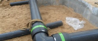
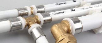
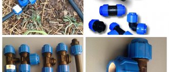
A flange socket connection is the most popular type of fastening of polyethylene pipes at home without welding. It is convenient to perform it on water pipes with a diameter of 50 mm or more. For smaller diameters you need to work with fittings or special clamps or clamps. Flanges are also used to connect copper, metal or cast iron pipelines to polyethylene pipelines.
Photo: flange for polyethylene pipes
A flange is a threaded part that is used to connect different types of pipes. Metal flanges are mainly used for gas communications, metal water pipelines, as well as for connecting water supply systems made of different materials. At the same time, to install polyethylene pipes with metal ones, a special type of flange is used, which has a thread on one side and a seal on the other. This allows for the strongest and tightest possible connection.
How to make a threaded connection of PE pipes with your own hands:
- Prepare the pipeline. To do this, cut the plastic pipe at a right angle, the same should be done with the metal one;
- If the place that needs to be connected to the polyethylene pipe does not have a metal thread, you need to do it. This work is carried out using special thread-cutting attachments;
- Next, you need to secure the flange to the pipe thread, do not overtighten, so as not to break the self-tapping connection. In this case, it is advisable to treat the threads with sealants or mastics before starting work to avoid leaks. Sometimes it is allowed to protect the threaded connection with a resin-treated cord;
- Now a plastic pipe, also treated with special substances, is inserted into the free end of the flange.
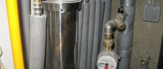
It is very convenient to work with flanges at home, but only if your pipe diameters are not too large, otherwise you will need special tools to install the connections. Their main advantage is that they are suitable for pressure plastic pipes. At the same time, fittings are very different: compression, electric-welded from alloy steel, cast from polyvinyl chloride.
Photo: pipe connection
To connect non-pressure polyethylene and polypropylene pipes with a diameter of up to 50 mm, fittings are used. The technology is as follows:
- Before starting work, make a project to calculate the number of fittings. You also need to determine the required diameter of these connecting devices and their material;
- Take care of purchasing tools for the job. You will need a shaped wrench, special clamps, sealants;
- Turn off the water supply. Pipes must be dry;
- Apply sealants to the surface of water supply lines, which protect against leaks;
- Then insert the fittings into the places where the pipes are separated. It is advisable to trim each communication to create a right angle in the structure;
- This connection of plastic pipes does not require any knowledge of threading tools or work experience. All you need is to cut the pipe to the required size and connect it using shaped elements.
- After finishing work, you cannot immediately turn on the water; the sealant needs to dry and harden. On average, its hardening period varies between 3 – 8 hours.
Fastening with a clamp is used only for non-pressure polyethylene pipes, otherwise the sewer will burst. A similar connection is used for fastening asbestos-cement pipes using free-flow concrete rings.
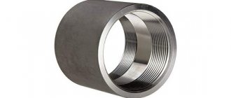
Photo: fitting for polyethylene pipes
Flange connection assembly
To ensure reliable joints on the pipeline, all types of flange connections are assembled in a strictly defined order. First, a randomly selected bolt is tightened with slight force, then the diametrically opposite one. The next pair should be a quarter of a circle away from the first. The remaining bolts are tightened in the same order. If there are only 4 holes on the flanges, tighten them crosswise.
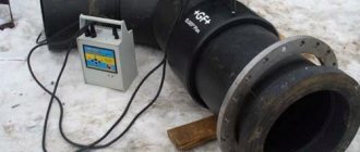
To ensure that the force is distributed evenly, the final part of the installation is carried out with tools that allow it to be controlled:
- hydraulic tension device;
- pneumatic impact wrench;
- manual torque wrench;
- hydraulic torque wrench.
Hand tightening should only be done by experienced workers. During the first day of operation, due to vibrations, shrinkage of the gasket material, and temperature changes, the strength of the connection is reduced to 10%. Therefore, during this period, tightening of the nuts is required.
Installation of all types of flange connections is simple, but only specially trained mechanics are allowed to carry it out. When laying or repairing pipelines with aggressive media or operating under high pressure, the progress of the work must be monitored by an engineer. The assembly of non-pressure systems (sewage, irrigation) can be carried out by unskilled workers.
Detachable pipe connection without threads and without welding
There are many more ways to connect pipes without threads so that they can be separated later.
With coupling
There are situations when difficulties arise in replacing a piece of pipe without threads. In this case, use a special coupling, which consists of:
- housings;
- 4 washers and two nuts;
- two rubber gaskets.
In order to connect two pipes, you need to thread their ends through nuts, washers and gaskets and connect them inside the housing. Now all that remains is to screw in the nuts. The gaskets are compressed and provide a tight seal; if this does not happen, then another gasket ring should be added.
The most important thing is to choose a coupling of the required diameter. If you take a large coupling, then leaks cannot be eliminated.
Flange connection of steel pipes
Joining using flanges is mainly used for steel pipes. A flange is a part for the repair and installation of individual parts of a pipeline. When combining pipes in this way, several points are taken into account:
- The nuts should not be skewed, so the order of screwing them is as follows: first, turn the nuts located one against the other, and not around the circumference.
- For water supply, use a rag cardboard gasket impregnated with drying oil.
- Heating pipes require a lining made of asbestos cardboard.
- The ends of the bolts should not protrude more than halfway from the nuts.
- The inner diameter of the gasket should be slightly larger than the diameter of the pipe, and the outer diameter should not touch the bolts.
- You should not use several gaskets for one flange, this will reduce the tightness.
The flange connection is used for pipes of both small and large diameters. Can be used for gas pipes, chimneys, sewers and others.
Pipe collet connection
For the installation of plastic pipes, collet fittings are used, which consist of a body in which a crimp ring and a rubber gasket are placed. Advantages:
- low cost and availability;
- reliability;
- ease of installation;
- Possibility of reusing the collet.
Please note that sometimes this fastening becomes loose, so it is necessary to tighten it from time to time. Connecting pipes in this way is simple: first, insert the collet inside the pipe, and then tighten the outer nut
Do the same with the second pipe.
It should be remembered that this part exerts high pressure on the pipe, so when tightening the nut it is important not to twist it in order to prevent the appearance of cracks and cracks. Connecting pipes in this way is simple: first, insert the collet inside the pipe, and then tighten the outer nut
Do the same with the second pipe. It should be remembered that this part exerts high pressure on the pipe, so when tightening the nut it is important not to twist it in order to prevent the appearance of cracks and cracks
Connecting pipes in this way is simple: first insert the collet inside the pipe, and then tighten the outer nut. Do the same with the second pipe.
It should be remembered that this part exerts high pressure on the pipe, so when tightening the nut it is important not to twist it in order to prevent the appearance of cracks and cracks
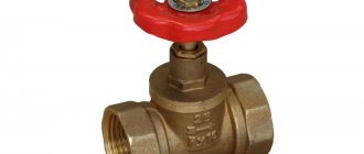
Using clamps
There are different types of connections, one of them is quick-release pipe joining. It is carried out using clamps - a device in the form of a metal ring with a tightening mechanism: nuts with metric threads. This method is designed to create a tight seal between a hose and rubber pipes with a solid base. Installation is effortless.
Clamps can be different, for example, on sale you can find spring wire clamps that work on the principle of clothespins. Despite the simplicity of the design, such devices can ensure complete tightness of the connection.
Compression fittings
Compression fittings are used to connect plastic pipes. These parts allow you to make branches and turns, and also increase the length of products. Advantages:
- does not require constant monitoring, there is no need to periodically tighten the bolts;
- can be laid in concrete or at depth;
- high degree of tightness, not susceptible to corrosion;
- easy and quick installation.
Basic parameters of flange fasteners
Working pressure is the pressure with which a liquid or gas flows through a pipeline. This term also means the highest excess pressure at which long-term operation of the pipeline, fittings and connecting units is possible at the operating temperature of the environment. The higher the operating pressure, the stronger the fasteners must be used when constructing the pipeline. The strength of the fastener is determined by the characteristics of the material from which it is made and proper heat treatment. It is necessary to compare the parameters of the working environment and the technical characteristics of the material. Thus, steel 35 is designed for use at operating pressures up to 100 kgf/cm² and temperatures from -40 to +400 degrees Celsius. Accordingly, when the operating pressure increases to 200 kgf/cm², you should choose a different grade of steel for the manufacture of fasteners, for example, 20X13.
Working temperature. It is one of the most important parameters when choosing fastening materials. Working temperature is the temperature of substances transported through the pipeline. When choosing a steel grade, the ambient temperature is also taken into account. Each material has its own operating temperature range at which the reliability of fastening is guaranteed during long-term operation.
If two pipelines have the same nominal pressure, but one of them is planned to operate at ambient temperatures down to -30 degrees Celsius, then a 35 steel stud is used for flange connections. If the pipeline is used in harsh climatic conditions with ambient temperatures down to -70 degrees Celsius , it is necessary to use fasteners made of cold-resistant steel 09G2S or 10G2 for connections.
Working environment. In accordance with the temperature and physico-chemical parameters of the working environment, flange fasteners must be selected. The material from which it is made must meet the requirements depending on the properties of the working environment, for example, anti-corrosion, resistance to high temperatures, aggressive environments. For aggressive environments, choose fasteners made from steel grades 20X13, 14X17N2, 12X18N9T.
Thread diameter. Fastening elements can have both internal threads, such as nuts, and external threads, such as bolts, studs, and others. The thread has a pitch that can vary in metric or inch systems. Depends on the regulatory documents to which the specific project refers. The first thread pitch is measured in millimeters, the second is measured in inches. Inches are indicated in whole and fractional numbers, in increments of ¼ inch.
Thread pitch. This is the distance between the nearest vertices of threads lying parallel to one axis. There are two main groups of fasteners: with coarse and fine pitch. The choice depends on the specific specification; if it does not specify much, then the main thread pitch is considered to be large.
For example, an M6x20 bolt means a fastener with a fine thread pitch of 20 mm, a nominal diameter of 6 mm.
Turnkey size. In the technical literature it is designated by the symbol S; in fact, the turnkey size is the distance between two parallel faces of a hexagonal or octagonal bolt. Each standard thread diameter corresponds to the size of the working profile of the fastener. Knowing it, you can determine the appropriate key.
Bolt length. When designating a numerical expression for the length of a bolt, only the length of the rod itself is taken into account, without taking into account the head. For example, for an M6×50 bolt its length is 50 mm. In this case, the overall overall length of the bolt will be greater by the height of the head, which is 4 mm, that is, 54 mm.
Hairpin length. As a rule, the length of the stud specified in the specification means the overall overall length, unless otherwise provided in other documents. For example, GOST 22032-76, which regulates the use of studs with a screw-in end, requires specifying the length of the stud without taking into account the screw-in end.
Threaded end length. That part of a stud or bolt with threads onto which a nut is supposed to be screwed.
Coating. In the case of using fasteners on highways and assemblies that are expected to be exposed to aggressive environments, the bolts and studs are coated with a protective layer of zinc, nickel or chromium.