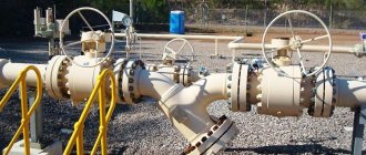
Hello, dear reader! If it is necessary to repair water supply lines, eliminate “accidents” on them, replace plumbing fixtures, the water supply in such cases can be stopped by a flange shut-off valve installed at the entrance to the apartment.
However, emergency situations arise not only in your apartment, but also in city public utility systems. Therefore, all pipelines and mains supplying water, gas and heat to our homes are equipped with modern shut-off valves, ensuring resource conservation, reducing the cost of services provided and saving money.
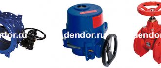
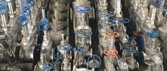
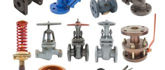
Classification of reinforcement by design
Several types of pipeline fittings are produced, differing in the shape of the shut-off and control valve and its operating principle:
- valves;
- valves;
- gates;
- taps;
- valves
Let's consider each type of reinforcement separately.
Valves
Valves are a type of pipeline fittings in which the shut-off or control element moves using a threaded pair in a direction parallel to the axis of the pipeline.
The list of their main advantages includes:
- low coefficient of friction of the sealing planes at the moment the devices are activated to close as a result of the movement of the shutter perpendicular to them, which reduces the risk of damage (scuffing);
- the height of the product is not high compared to gate valves, due to the fact that the valve has a short spindle stroke.
The disadvantages of valves include the fact that they are longer than gate valves, since they require space inside the body to be able to turn the flow.
Valves
A valve with a shut-off or control element that moves perpendicular to the flow axis of the medium transported in the system.
Gate valves are available in different designs; in the manufacturers' catalogs you can find the following products:
- with a locking mechanism in the form of a rectangular plate (gate), wedge or disk;
- with retractable and non-retractable spindle;
- full bore or with a narrowed flow hole;
- body - cast, welded or stamped;
- To ensure the tightness of the body/cover interface, an stuffing box or bellows seal is used.
The advantages of steel flanged valves are due to:
- no need to overcome the pressure of the environment when moving the shutting organ;
- straightness of movement of the working substance flow, without turns;
- ability to work in systems with viscous media;
- short construction length, which means they can be installed in limited space;
- the ability to supply the working substance in any direction;
- ease of installation, repair and maintenance.
The disadvantages of valves include:
- low speed when triggered;
- large building height;
- restrictions on use in transport systems for media consisting of solid particles.
Gates
Gates (dampers) are devices with a disc-shaped locking body that rotates around its axis.
The movement occurs in a perpendicular direction or at an acute angle. They are used for installation in systems with large pipe diameters, low media pressure levels and reduced requirements for the tightness of the shut-off element, for example, on ventilation and air conditioning ducts, gas pipeline structures.
Cranes
For valves of this type, the shut-off element is a body of rotation or a segment thereof, moving in any direction relative to the axis of the pipeline. There is another name for a faucet shutter - a plug. The plug has a hole through which the flow of medium moves. In the “open” position of the valve, the hole is in the same plane with the flow axis, in the “closed” position - in a perpendicular position to the flow.
According to the direction of flow they are divided into:
- walk-through - with a constant flow direction;
- angular - the flow changes direction at a right angle;
- three-way - with one outlet and two inlet pipes.
The shape of the valve valve element can be:
- ball;
- conical;
- cylindrical configuration.
To ensure that the plug is tightly pressed to the surface of the body, a stuffing box or spring is used, put on a threaded rod and tightened with a nut, like with tension taps.
To ensure a high level of tightness, a lubricant is used to fill the microscopic gaps between the planes of the body and the plug.
Lubrication is also necessary to reduce the force required to rotate the bolt.
Valves
A mechanical device through which the flow of a working substance maintains the direction of movement or turns at an angle.
Available in several design options, differing in:
- shutter shape - disc-shaped, needle-shaped;
- number of saddles - single-saddle, double-saddle;
- location of the running nut - external and submersible thread types;
- The method of sealing the interface between the housing and the lid is an stuffing box or membrane type of seal.
Depending on the purpose, flanged valves are:
- constipating;
- regulatory;
- safety;
- bypass;
- reductionist;
- reverse;
- drain;
- suction, etc.
Recommendations for valve selection
Due to the fact that flanged valves are widely used, their selection should be approached extremely carefully and scrupulously. If the device is chosen incorrectly, there is a chance that it will soon fail. There are several key parameters to consider when purchasing a tool:
- material from which the body is made;
- type of shell;
- type of drive mechanism.
Valves whose body is made of steel are wear-resistant and durable, but it is recommended to install them on pipelines through which steam, gas, oil products or water are transported. The advantage of alloy steel is that it can withstand low ambient temperatures reaching 60 degrees below zero.
Stainless steel valves have high resistance to corrosion and are also resistant to aggressive chemical elements. Stainless steel flanged valves are widely used in the food industry, since it is necessary to maintain high purity of the environment that is transported through the pipeline. Cast iron parts have low resistance to environmental factors, and they are also fragile and have a high specific gravity. It is recommended to install exactly such mechanisms on water supply systems.
When purchasing a shut-off valve, you need to take into account the design of its body, which can be all-welded or dismountable. The size of the part and the ability to carry out one or another type of repair work will depend on the design. All-welded spare parts have a one-piece body, which does not provide for the possibility of carrying out inspection measures, therefore such a valve should be installed in those areas where adjustment of the flow of the medium occurs extremely rarely. This precaution is necessary in order to extend the life of the device.
The design of dismountable valves consists of individual spare parts, which, if necessary, can be replaced if any of them becomes unusable. It is precisely because the valve is disassembled that it can be used to carry out any type of repair work, but such a tool is very expensive.
Depending on the features of the technological process, you can select a flanged valve with a suitable control mechanism. The simplest drive mechanism for flange fittings is a handle, with which the valve is switched to open or closed mode. When choosing a valve to regulate the flow of thick substances, it should be taken into account that the handle must be strong and made of durable materials.
Another common type of drive mechanism is a gearbox, which must be installed on pipes if their cross-section is more than 300 mm. The rod is driven by a flywheel, which begins to rotate when the toggle switch is switched. Automatic devices are represented by pneumatic and electric control systems, with which you can control the valve even from a distance. Such devices contribute to the most efficient regulation of all technical processes.
To ensure proper operation of the flange shut-off valve, it is recommended to purchase spare parts only from official and reliable suppliers. Otherwise, there is a risk of buying a fake, which will become unusable after a short period of time.
Classification by connection method to workflow
Types of connecting fittings to the process have been developed in several options:
- flanged - flanged fittings are made with hardware parts on the connecting pipes (flanges). They can be square, hexagonal or round in shape with evenly spaced holes for mounting bolts. The pipeline must also have a counter flange with similar connecting dimensions;
- coupling - devices are connected to the process using couplings with internal threads;
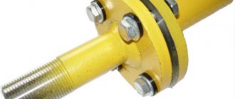
- pin-type - the fittings are fastened using an external thread with a collar under the control; a sealing gasket is used to seal the connection;
- fitting - this type of connection is a threaded pair, when fittings with external threads are attracted to the pipeline with a union nut;
- welded - devices are attached to the pipe by welding.
Standard flange installation
Quote from John H. Bickford, Introduction to the Design and Use of Bolted Joints:
All that important clamping force that holds a connection—and without which there would be no connection—is not created by a good connection designer or by high-quality parts. It is created by a mechanic on the job site using the tools, procedures and working conditions provided to him... And one more thing: the final, significant force creator is the mechanic, and the time of creation is during assembly. Therefore, it is very important for us to understand this process.
The industry has recognized the critical nature of installation and assembly for several years.
In Europe the emphasis was on ensuring that co-manufacturing was carried out by trained and tested technicians and this led to the publication of a European technical standard: TS EN 1591 Part 4 entitled “Flanges and their connections. Design rules for a round flange with gasket. Connections. Qualification of personnel in the assembly of bolted connections installed on equipment subject to the Pressure Equipment Directive (PED).”
The standard provides a methodology for training and evaluating technicians involved in the fabrication and breaking of flange joints and can be considered similar to the training required for welders working on a pressure vessel. Its publication demonstrates the importance placed on competent process control of joints in ensuring flange tightness.
The gasket is just one of many reasons why a bolted flange joint can leak.
Even when all the complex interconnected components of a bolted flange joint work in perfect harmony, the single most important factor leading to the success or failure of that bolted flange joint will be the attention given to proper installation and assembly procedures by the person installing the gasket. If done correctly, the assembly will remain sealed for its expected service life.
Note
Types of flanges
The flange is the connecting part of pipes, shut-off and control valves, control and measuring devices that are part of the pipeline structure.
The flange type of connection of pipeline fittings facilitates easy access for maintenance, repair and replacement of system elements. Flanges are usually internally threaded or welded. For their manufacture, various materials are used: gray and ductile cast iron, high-strength cast iron with inclusion of nodular graphite, brass, aluminum, bronze, plastic, forged carbon alloy steel or stainless steel.
The flange connection design consists of two flanges secured with bolts and a gasket between them to ensure tightness.
The gasket has the shape of a ring made of an alloy of high-alloy steel, brass, bronze, fluoroplastic, dense rubber, rubber elastomer, ebonite and other materials. It is installed between the surfaces of two flanges, filling microscopic cavities on them and smoothing out unevenness. The method of its installation depends on the shape and design of the sealing surfaces of the flanges, which may have:
- tenon and groove;
- protrusion and depression;
or be:
- flat with a connecting protrusion;
- flat welded without protrusion.
Tongue and groove flanges
The sealing surfaces of products of this type must match. One flange is made with a protruding ring (spike), and the counter flange has a machined groove in a similar location. The connection is sealed with a gasket, which must correspond to the height of the groove or be slightly smaller, and not exceed its width by more than 1/16.
Products with a sealing surface having a projection or depression
Flanges of this type are also the same. One part has an area on its surface that extends beyond its plane (male).
The mating flange has a corresponding cavity (mother) in the sealing surface, bored to a depth equal to or less than the height of the protruding part.
Flat surface of products with a connecting protrusion
Flat raised flanges have a flat sealing surface with the gasket extending 1/16 or ¼ above the bolting surface. The seal has the shape of a ring and is completely recessed into the bolted connection.
Flat weld face flanges without projection
A flat welded flange without a protrusion has the simplest design, is made of steel grades VST3SP2 and VST3SP3 in sheet form and is used to connect elements of pipeline lines for a nominal pressure of 1 to 25 kgf/cm².
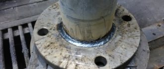
During installation, the product is screwed onto the end of the pipe and welded with two welds along the entire circumference of the pipe.
Our offers
carries out wholesale sales of all types of shut-off valves, both in straight-through and corner versions. Our advantages are the low cost of products, as well as their fast delivery to all regions of the Russian Federation and the CIS countries. We have 15 branches and 20 warehouses with a total area of 25,000 m2 in the regions of Russia. This allows us to ship products from the warehouse closest to the final delivery point. To place an order for a wholesale batch of pipeline fittings, use the services of our online store.
Design types and principles of operation of valves
Structurally, the valve is a one-piece cast or welded body with a cover and a partition in the middle. In the body cavity there is a breech body, consisting of a stationary element - the seat and a moving part - the spool. The saddle is located in the middle part of the partition and is equipped with a passage hole.
The spool is attached to a spindle passing through a stuffing box or bellows type seal and a cover to the steering wheel. The steering wheel can be controlled manually or electrically. For connection to the pipeline line, the housing has inlet and outlet pipes.
Its operating principle is based on the transmission of torque from the steering wheel through the spindle to the spool. The spool, making translational movements, reaches the lowest position, where it is pressed tightly against the seat and completely stops the movement of the medium.
According to the design of the shut-off body, the valves differ in:
- ball rotary - in them, instead of a spool and a seat, a saddle with a ball-shaped shutter fixed to it, which has a through passage for the medium, is used as a shut-off element. The ball rotates freely around its axis, changing the position of this hole to pass, block or adjust the intensity of the flow of the working substance;
- wedge - the movable part of the shutter has a shape in the form of a plate (wedge) narrowed on one side. The wedge covers the saddle in a horizontal plane parallel to the flow of the transported substance, forcing its flow to make a double bend at an angle of 90º.
Electrically operated valves
Valves equipped with an electric drive are installed in water treatment systems of swimming pools. When voltage is applied, the electrified valve is activated to open or close the throughput hole, regulates the flow of water, and automatically controls the process of filling and topping up water in the pool.
In the absence of electricity, the valve can be controlled manually.
Features of the use of valve 15kch19p
A flange shut-off and control valve is installed in the system in a place convenient for the plumber, which will be accessible for quality service. When installed in an open space, the device must be protected from precipitation and mechanical shock. When conducting hydraulic tests of the pipeline system, the flange shut-off valve 15kch19p must be fully opened, and additional stress should not be created at the junction of the valve and pipe. When installing devices, it is necessary to tighten the connections where gaskets and seals are located to prevent depressurization of the pipeline.
During operation, the 15kch19p flange shut-off valve requires periodic (once a year) lubrication of its spindle and its moving part with an antifriction compound. If the tightness of the oil seal was broken, and it was not possible to repair it by tightening it, the element must be replaced with fum or filled with APK-31 GOST 5152-84. It is necessary to repair the 15kch19p valve if the gasket or seal needs to be replaced. It is prohibited to repair valve defects when there is pressure in the pipeline. If the shut-off valve 15kch19p has expired, it should be dismantled and sent for recycling. When operating the devices, the use of additional levers is not allowed; safety precautions in accordance with GOST 12.2.063-81 must be strictly observed. During transportation and storage, the shut-off valve 15kch19p must be closed. On average, our cast iron valve 15kch19p can operate 3500 cycles, after which the device needs to be replaced with a new one.
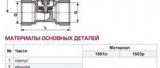
Manufacturing technology and groups of materials used
For the manufacture of components and parts that make up the valve, various materials are used, which are divided into 4 groups:
- Materials for making the case. They must have good casting properties, a sufficient level of strength and corrosion resistance, and be subject to mechanical processing. Basically, the valve body is manufactured using casting technology.
- Materials for sealing the places where the spindle passes through the cover. Gaskets must be elastic, heat-resistant, moisture-resistant, durable and inexpensive products.
- Seals in the area of the seat and valve. The material for their manufacture must also have elasticity, wear resistance and anti-friction properties.
- Lubricants that reduce the coefficient of friction in the moving parts of the valve.
The body materials most often used in the manufacture of valves are:
- brass. This is a yellow plastic metal that can be easily machined (grinding, polishing, etc.). It is an alloy of pure copper with a small amount of impurities. Among the alloying elements of alloys, zinc and tin can be distinguished, which increase the anti-corrosion properties and thermal conductivity of the material. Brass valves are one of the most reliable models in operation, but expensive;
- cast iron. A heavy gray metal with high strength and corrosion resistance. Cast iron valves are inexpensive, can withstand ambient temperatures up to 200º, but are not very resistant to dynamic loads, so they can easily crack from a strong blow to the body.
- steel. The material is quite plastic and easy to process. The steel reinforcement body is resistant to mechanical stress and strong impacts. Products for the manufacture of which high-alloy steel (stainless steel) is used, in addition to high strength, have absolute resistance to any type of corrosion processes, resistance to high temperatures, and durability.
Purpose and application of shut-off flange valves
A flanged valve made of steel or cast iron is mainly used to turn on the flow of a medium or completely turn it off during repair work, switching individual lines and equipment. The working medium can be any liquid, steam or gaseous substance.
The advantages of shut-off valves include:
- small geometric parameters;
- low hydraulic resistance;
- absence of stagnant zones.
The disadvantages are:
- the need for regular maintenance;
- limitation in application by the level of pressure in the system;
- low wear resistance of the connection points between the housing and the pipeline.
Principle of operation
The flange valve design can be straight-through, straight-through or angled. In direct-flow valves, the direction of the fluid is maintained, but the spindle is located obliquely to the axis of the passage, and not perpendicular. The design of direct-flow valves is intended to reduce hydraulic resistance, as well as to straighten the flow of the working medium.
With straight-through valves, the fluid flows in and out in the same direction, but inside the master cylinder it makes two 90-degree turns. With the help of such valves, the movement of liquids that have high temperatures and pressures is blocked. Excessive loads do not pose any danger to straight-through flanged valves, since the valves help maintain tightness. But inside such structures there is often high hydraulic resistance, which leads to stagnant zones appearing in the cylinder.
With the help of angle valves, the fluid flow is rotated 90 degrees, and they are installed in those areas where the pipeline turns. If we compare such a valve with passage parts, they have lower hydraulic resistance.
Installation
When installing a steel flanged valve, perform the following steps:
- clean the flange surfaces from dirt and scale;
- inspect the threads of bolts and nuts for areas damaged by corrosion. If damage is detected, the hardware should be replaced or repaired;
- remove burrs from threaded parts;
- For fasteners, lubricate the threaded areas adjacent to the flange or washer. Lubrication will reduce the coefficient of friction when tightening bolts, reduce the number of bolt failures and extend their service life;
- install a new O-ring, aligning it in the center;
- check the alignment of the flanges according to ASME B31.3 regulations;
- adjust the position of the nuts so that the thread of the bolt rises 2-3 turns above its upper surface;
- tighten the bolts with any torque wrench.
Found something interesting for yourself? Subscribe to our channel and share useful ideas on social networks.
Device
In the classical sense, a flanged shut-off valve consists of a body with flanges and a seat, a spindle, a yoke assembly, and a steering wheel (flywheel). The first is made of high-carbon or stainless steel, cast iron, brass and polymer composites.
The yoke assembly is a part of the body or a running nut, through the threads of which the rod, rotating, moves the working element fixed to it (spool, cone).
The valve can be disc-type (spool-type) or conical. The sealing surface of a poppet valve can be flat or conical. To make the latter, a conical chamfer is machined into it. Conical metal/metal seals are used for environments with high pressures and the presence of suspended particles.
Flat seals perform well in all media without suspended particles. Rubber or polymer gaskets are installed in the saddles of such valves.
Shut-off valve 101
Look
Shut-off valve 120
Look
Shut-off valve 220
View Torque is imparted to the spindle by a handwheel or mechanical drive. The rod can also move under the action of an electric, hydraulic, or pneumatic actuator. In this case, its movements are reciprocating without a running nut. Such drives are used in industry.