Gate valves and ball valves are popular types of pipeline fittings. Their use optimizes the design of pipelines, ensuring efficient organization of the production process and safe operation of the system and technical devices. The products are responsible for controlling the movement of the working medium and are used to shut off/open the flow, as well as regulate the intensity of the supply of the substance. At the same time, the design and operational capabilities of various types of fittings have certain features and discrepancies. That is why it is better to find out which valves and ball valves are better before installing the equipment at the preparatory stage.
Valves
The gate valve is a simple and reliable shut-off device designed to operate in energy mains with various working environments. According to the design and the material used, this element can withstand pressure in the system up to 25 MPa.
Structurally, the valve consists of the following parts:
- housing closed with a bolted lid;
- shutter;
- a spindle with a nut making up a screw pair;
- flywheel;
- wedge or damper (taking into account the design of the element).
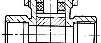
Rice.
1. Valve diagram The cross-section of the channel with the working medium is blocked by a wedge or valve when the flywheel rotates, moving the spindle in the nut. Inside the body there are seats with mirror surfaces that seal the shutter. On shut-off elements for large pipeline diameters, a pneumatic, electric or hydraulic drive is installed, which automates the operation of the device. The drive mechanism is equipped with a gearbox that converts torque. The valve body parts are made of cast iron or steel (alloyed or stainless). The valve element is made of steel, selecting the material according to the properties of the working environment under which operation is expected. Typically, valves are used to operate in an open or closed state, without the function of adjusting the open cross-section of the line. Leaving the locking part in an intermediate position will result in deformation of the valve, resulting in damage to the device.
Comparison
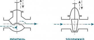
The main difference between a valve and a faucet is that the main element of the first shut-off device is a partition that moves perpendicular to the flow of liquid or gas in the pipeline. The main element of the faucet is a valve with a channel made in it, which, when placed parallel to the flow or at a slight angle to it, increases the intensity of fluid movement in the pipe, and when placed perpendicular to the flow or at a large angle to it, reduces its intensity.
The difference between the considered types of locking elements can also be traced in the following aspect:
- wear;
- requirements for spaces outside the pipeline cross-section;
- scope of application, prevalence of inclusion in the structure of household faucets.
Having determined what the difference is between a valve and a faucet, we will record the conclusions in a small table.
Types of valves
The operating principle of the valve is based on blocking the flow of the working medium in the main line, due to the movement of the valve body in a perpendicular direction. Several varieties of these devices are manufactured, taking into account the design of the valve element and the location of the threaded pair. Based on the listed features, valves can be:
- wedge (with a hard, double-disc, or elastic wedge), for example 30s41nzh, 30s64nzh
- parallel - 30h6br;
- gate;
- hose
Rice.
2. Wedge valve Based on the location of the threaded pair, the locking devices require retractable and non-retractable spindles.
In wedge fittings, the working flow is blocked by a wedge that fits tightly to the inclined surfaces of the seats, ensuring tight operation. The wedge design can be:
- rigid (30s41nzh) – in the form of a wedge-shaped steel plate, fitted to the saddles; the wedge is characterized by high strength, but rigidity can lead to jamming when temperature or pressure changes;
- double-disc (30ch6br) – made of two fastened wedges that adapt to the shape of the seats in the body when lowered; the risk of jamming is minimal, with moderate wear of surfaces;
- elastic - a similar design, with a spring-loaded connection of the wedges.
In parallel valves, the gate elements are located parallel, in the form of two disks, pressed by a wedge to the seat mirrors.
Gate valves block the flow of the working medium with a perpendicularly located plate. Another name for such fittings is knife fittings, since the movement of the shutter resembles cutting, blocking the flow.
Hose valves are used less frequently than others. Their design is completely different from the others. The flow of the working medium passes through the hose, which is clamped by a shut-off element, blocking the nominal passage. These fittings are installed on small-diameter pipelines, slurry pipelines and other networks transporting liquids with impurities.
In a locking element with a sliding spindle design, the nut is located outside the housing cover, inside the flywheel. When rotated, the rod extends, moving the bolt. The running unit is not exposed to the working environment, which increases the service life of the valve.
Rice. 3. Gate valve with a rising spindle (30s41nzh, 30s64nzh, 30ch6br)
This device is simpler and more reliable in operation. Easy access to the stuffing box simplifies maintenance. Disadvantages - large mass, with the need for free space at the top of the element for the rod to exit.
In valves with a non-retractable spindle, the threaded connection is placed inside the body. When the flywheel rotates, the shutter element moves along the spindle along with the nut.
The location of the running gear in the working environment complicates operation. But this design benefits in weight and size.
Rice. 4. Gate valve with non-rising spindle
The table shows the comparative characteristics of valves with a retractable and non-retractable spindle device:
| Characteristic | Non-retractable spindle | Retractable spindle |
| Nominal diameter, mm | From 40 to 1200 | From 15 to 1,200 |
| Ultimate pressure, MPa | 1,6 | 10 |
| Working environment temperature, °C | -15 to +130 | -70 to +450 |
| What formulations are they used for? | Pure cold and hot water, non-aggressive environments | Components of any degree of aggressiveness |
What is a faucet?
A faucet is a shut-off element, the main part of which is a valve, presented in the shape of a ball, a cone or a cylinder. They have a channel with a diameter that is sufficient to ensure the passage of flow if the corresponding channel is located parallel to the flow or is located at a slight angle to it. In turn, when the channel is placed perpendicular to the flow (by rotating the ball, cone or cylinder in which it is made) or at a large angle to the flow, the movement of liquid or gas in the pipe stops or its intensity decreases.
Changing the position of the valve is carried out by rotating a spherical, cone-shaped or cylindrical valve around its axis perpendicularly or parallel to the flow (this is not important, the main thing is to achieve the necessary tightness).
The faucet, like the valve, is characterized by a high degree of tightness. Therefore, it can be installed on pipelines with high pressure. At the same time, cranes are not characterized by the main disadvantage of valves - wear. Provided that the locking device in question is properly lubricated and maintained, it can last a long time.
The valve is thus excellent for regulating the rate of movement of liquid or gas in a high-pressure pipe. This explains its frequent use as a locking mechanism at the final section of pipelines. For example, as the main element of household faucets, which are located in bathrooms, kitchens, and showers.
The valve, as a rule, does not require a large space outside the pipeline cross-section, since its main element - the valve - rotates around its axis within the pipe. True, additional space may be required for the control valve and other mechanisms that complement it.
Features of labeling and packaging
A sign is attached to the valve indicating:
- symbol of the product;
- nominal pressure in kgf/cm2;
- passage diameter in mm;
- manufacturer's trademark;
- release dates;
- serial number.
The product is packaged in accordance with state standards and manufacturer's specifications. The inlet and outlet openings are closed with transport plugs. The contact surfaces of the flanges protect against possible damage during transportation. The shutter elements are installed in the closed position.
Diameter
There are different diameters of the passage hole and connecting pipes. Valves according to the passage diameter can be:
- full bore;
- incomplete bore.
The first option means that when assigning a valve to a pipe with a diameter of 200 mm, the passage in the valve will correspond to the passage in the nozzles. With a partial bore design, the internal diameter in the valve is smaller than the internal diameter of the nozzles.
Ball valves are:
- also full bore;
- standard passage.
We've already sorted out the full bore issue. With standard bore valves, the same is true as with partial bore valves. The internal diameter of the valve is one order of magnitude lower than the diameter of the nozzles.
Installation of valves
Trained personnel with the necessary skills are allowed to install the engines after familiarizing themselves with the contents of the product passport and operating instructions.
Installation is carried out under the condition of a closed supply of the working medium to the area where the shut-off valves are installed.
If the valve weight is large, a lifting device is used. The locking element is grabbed with a strap sling by the body. Do not pick up the flywheel.
Before installation, check that the flanges are installed correctly on the main line, with parallel planes, without distortions or deviations.
After installation, the shut-off element should not experience additional loads from the pipeline.
Before installation you must:
- depreserve the valve by removing the preservative grease using a clean rag soaked in solvent;
- check the integrity and completeness of the device;
- tighten the bolted connections on the cover;
- remove the transport plugs on the pipes;
- check the tightness of the shutter, making sure there are no foreign particles or debris.
Installation of a flange valve is performed in the following order:
1) the shutter element is moved to the installation location;
2) receiving flanges with branch pipes are pre-attached to the valve;
3) the fittings are placed on the pipeline in the installation opening using a lifting mechanism;
4) the pipes of the external flanges are tacked by electric or gas welding;
5) remove the valve by removing the bolts from the flanges;
6) weld the joints, ensuring tightness;
7) install the valve, placing the seals and tightening the bolts.
When tightening, do not use extensions for keys to increase the torque. The bolts are tightened evenly, first on one side, then on the other, in a cross pattern.
Rice. 5. Appearance of the installed valve
Upon completion of installation, check the operation of the device. Gradually apply pressure to the line.
It is important to check the tightness of the connections. After installation, the system is subjected to pressure testing, applying pressure 25 percent higher than the nominal one.
The pressure is maintained for two minutes, checking the tightness visually. If there are leaks of the working medium, additional measures are taken to eliminate the problem.
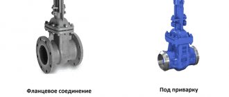
Functional purpose and design features
Steel flanged valves differ from other types of pipeline fittings in that the locking mechanism in them moves perpendicular to the movement of the working medium. Such structures are produced in diameters of 15-2000 mm; they are intended for installation on pipelines whose operating temperature does not exceed 600 degrees and pressure up to 25 MPa.
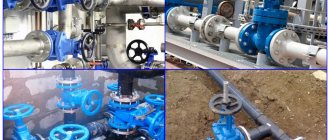
Gate valves are widely used in all areas of industry:
- water supply systems and heating communications of housing and communal services;
- oil and gas transport systems;
- main pipelines of the energy industry.
The spread of this type of pipeline fittings is due to the following operational advantages:
- simplicity and maintainability of the design;
- minimum construction length;
- reliability in difficult operating conditions;
- low level of hydraulic resistance.
Gate valves also have disadvantages, the main one of which is the large overall height of the structure, which is especially typical for products with a sliding-type spindle, in which the stroke of the rod must be equal to the full diameter of the passage opening. Also a disadvantage is the long opening time and the tendency to operational wear of the sealing elements, as a result of which the valves require periodic maintenance and.
Please note that the design features of the valves do not imply their use as control valves - during operation, the locking mechanism must be in the extreme open or closed position
, and not in the intermediate.
Almost all types of valves are produced in a full-bore configuration - the cross-section of their passage opening is identical to the diameter of the pipes on which the product is installed. Reducing valves (with a narrowed cross-section of the passage opening) are also produced, but they have a narrow scope of use - they are installed only on pipelines, in order to control the valves on which it is necessary to reduce the torque exerted by the working medium.
The control mechanism in shut-off valves is a hand wheel; there are also designs equipped with hydraulic or electric drives, less often with a pneumatic drive. Large-sized valves, which are manually operated, are equipped with a gearbox to facilitate opening efforts.
Manufacturing technology and materials used
Valves, depending on the manufacturing method, are classified into cast and welded. The casting method produces steel, aluminum and, using welding joints, titanium and some types of steel products. In terms of strength and reliability, welded structures are practically not inferior to their cast counterparts.
The sealing elements of the fittings can be made of fluoroplastic, brass or rubber. Elastic materials (rubber and synthetic rubber - EPDM) are most often used in production (where the walls of the locking mechanism are covered with rubber) and hose structures (the pinch hose is made of rubber).
The valves have a unified marking according to GOST No. 9698, type 30nzh42p du50
, wherein:
- 30 - nomenclature of fittings (number 31 can also be used);
- nzh - designation of the material from which the structure is made, in this case nzh - stainless steel (s - carbon steel, ls - alloy steel, h - cast iron, tn - titanium);
- 42 — model number;
- p - material for manufacturing the sealing elements (p - plastic, br - bronze or brass, p - rubber, p - plastic);
- DN50 - diameter 50 mm (varies between 15-2000 mm).
Installation of flanged valve DN219 (video)
Maintenance
To eliminate malfunctions and the danger of emergency failure, periodic inspections of the fittings are carried out, checking the operation of the device. The frequency of inspections, including maintenance, is determined by the system adopted at the enterprise and the manufacturer’s conditions given in the passport.
Maintenance includes the following operations performed taking into account the technical condition of the element:
- lubricating the spindle threads with grease, in accordance with the manufacturer’s operating instructions;
- tightening the stuffing box seal by tightening the nuts that tighten the bushing;
- adding or replacing the oil seal - if the bushing is lowered to the lower position and the tightness is not maintained;
- lubricating the threaded connection between the spindle and the nut.
When tightening and replacing the oil seal, turn off the supply of the working medium, removing pressure from the valve.
The minimum frequency of maintenance is every six months.
Rice. 6. Valve maintenance
To comply with safety measures, it is prohibited:
- tighten, add, change stuffing box seals while applying pressure to the locking element;
- tighten the oil seal by hitting the bushing;
- dismantle and repair the valve without removing the pressure in the line;
- exceed the pressure when pressing the pipeline, established by the limiting characteristics of the fittings.
Personnel performs maintenance of locking elements using special clothing and protective equipment required by labor protection standards.
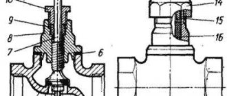
Valve or shut-off valve
The valve is very similar in appearance to a valve.
The principle of operation of the valve is quite simple: when the flywheel is turned, rotation is transmitted to the spindle located in the device body and having an oil seal; thanks to the worm gear, the spindle moves forward.
At the other end of the spindle there is a locking spool equipped with a gasket; when the valve is closed, the spool, reaching its lowest position, rests against the seat, due to which the flow of liquid or other medium is tightly shut off.
Hence the name of the locking device itself - the shut-off valve.
Shut-off valves are widely used in plumbing and heating systems and are shut-off and control devices that can have different appearance, design and application.
Valves also have their advantages and disadvantages.
On the plus side, the valve has the ability to smoothly adjust the flow and in most cases is repairable; when repairing it, the most common option is to replace the spool gasket or replace and tighten the stuffing box gasket.
By its design, the valve has fewer rubbing parts located in the working environment and, accordingly, has a longer service life compared to a gate valve.
Among the disadvantages - The main disadvantage of the valve is the increased hydraulic resistance for the flowing medium, which is determined by the design features of the valve, which increases the likelihood of the formation of stagnant zones in which impurities can accumulate that contribute to the corrosion process in the product body.
A small exception to the rule can probably be called direct-flow valves with an inclined spindle arrangement, where lower hydraulic resistance is achieved due to a more oriented seat position relative to the flow.
Valves may have a certain orientation relative to the flow movement, which must be taken into account when installing them.
Also, during operation of the valve, there is a possibility of the spool gasket coming off due to sticking or “drying out,” which leads to loss of sealing and the need for repairs. This situation can occur in cases where the valve is left closed or open for a long time, as well as when the system with the valve is left for a long time without a working environment.
Therefore, when installing valves, many plumbers may advise you to completely close and open the valve at least once a year for preventive purposes.
In any case, in some situations you cannot do without a valve, for example, in a collector system, thanks to the valves located in the collector comb, you can smoothly regulate the flow for individual water intake points or adjust the underfloor heating system, and for example, a thermal valve located in the heating system helps regulate the flow of coolant in heating radiators.
Pros and cons of valves
Valves are characterized by positive qualities:
- simplicity of the design;
- small installation length, which is convenient for installation in networks with limited space;
- versatility of application - suitable for pipelines of various diameters with different working environments;
- possibility of use in any direction of flow of working fluid;
- low hydraulic resistance.
The disadvantages are due to:
- long response time, there is no possibility of stopping in an intermediate position, with adjustment of the open section of the line;
- increased building height, especially for devices with a retractable spindle;
- rapid wear of the stuffing box seals, during labor-intensive repairs and replacement of elements;
- high cost of repairs, with low prices for the locking devices themselves.
Gate valves are more often used in industrial production conditions, installed on large-diameter power lines.
Ball Valves
A ball valve is a shut-off element with a shutter device in the form of a ball with a through hole, enclosed in a body, with a tight fit to the surfaces of the seat.
Rice. 7. Appearance of the ball valve
The ball valve consists of the following components:
- all-welded or collapsible body;
- rod with o-ring seals;
- a ball-shaped shutter with a mirror-polished surface;
- seat seals sealing the connection;
- handles in the form of a butterfly or a lever secured to the rod with a nut.
The operating principle is based on reversing the hole of the valve element, changing the location of the through hole in the ball relative to the flow of the working medium.
Rice. 8. Operating principle of a ball valve
Classification of ball valves
The body of ball valves is made of the following materials:
- brass - used on gas and water lines; not suitable for operation in conditions of high media temperature. For example, brass taps from Bugatti, Valtec or GALLOP;
- steel – products with the lowest price, with a wide range of standard sizes; should not be installed on cold water lines due to susceptibility to corrosion;
- stainless steel alloys - more expensive but effective devices when compared with steel ones;
- cast iron - used infrequently, since products made from modern materials are superior to them in most characteristics;
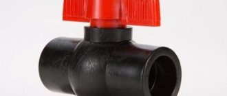
- polypropylene - installed in plastic pipelines; The service life and strength are comparable to brass products, with low weight and low price.
The valve element is made of a steel alloy or brass coated with an anti-corrosion compound (nickel, chromium). They produce products with plastic balls for use on appropriate water pipelines. But such taps are short-lived and are not suitable for working with hot water.
Seat sealing elements are often made of fluoroplastic, designed for operation at operating temperatures from -10 to +150 degrees. Metal seals are used less frequently. Such shut-off valves are distinguished by less tightness.
According to the installation method, taps can be:
- coupling - on threaded connections, which is convenient when used in household networks;
- welding - elements of small weight and size that guarantee the tightness of the connection; difficult to install, requiring the use of electric or gas welding;
- flanged - bulky fittings used on pipelines with a diameter of 40 mm or more; ease of maintenance and installation, if necessary, control the tightening of flange bolts.
Products with a coupling fastening method are made with external or internal threads for various installation conditions.
The body of ball valves can be:
- collapsible - consists of individual elements, with the ability to replace failed parts;
- all-welded, for example LD cranes - characterized by a low price, with complete replacement in case of malfunction.
The estimated service life is from 15 to 20 years. Considering this circumstance, the use of products with all-welded bodies is more economically justified.
Cranes are produced with the following control methods:
- manual - most often used in everyday life; controlled manually by turning the handle or butterfly;
- electric drive – activated by an electric motor through a mechanical gearbox;
- pneumatic drive is a switching method used in conditions where it is dangerous to use an electrical device.
Rice. 10. Electric ball valve
According to the design of the body, taking into account the type of passage, the following types of cranes are distinguished:
- full bore - when the diameter of the valve at the inlet and outlet matches the size of the hole in the valve element; used in networks where pressure losses are unacceptable;
- standard bore - the diameter of the pipeline passage is one size larger than the size of the hole in the valve.
The last of the cranes is easier to manufacture, at a low price, and reduces the risk of water hammer.
Reliability indicators
Manufacturers in the technical documentation indicate the following duration of operation of the shut-off valves.
For steel valves:
- average service life – 10 years from the date of commissioning until major repairs;
- designated service life - 30 years or 2500 cycles;
- Manufacturer's warranty – 1 year from the date of commissioning or 1.5 years from the date of sale.
For cast iron valves with rubber wedge, the average service life is 16 years or 4500 cycles. The indicator is higher than that of steel ones due to the absence of increased friction in the valve seals and stuffing box.
For ball valve:
- service life – 7, 10, 25 years (depending on the manufacturer and working environment);
- average resource – 25,000 cycles;
- The warranty period is 1.5 years from the date of sale (some manufacturers provide a 10-year warranty if the specifications are met).
The valves have a significantly higher number of operating cycles due to reduced friction in the valve and gland.
Advantages and disadvantages
The advantages of ball valves are:
- compact, with the possibility of installation on pipelines running parallel at short distances;
- low torque value, which eliminates the risk of stagnation and the formation of turbulence in the flow of the working medium;
- high tightness of the connection (class “A” according to GOST 9544-2015).
The disadvantages of this fitting are the need to monitor the condition of the working surface, the application of high torque to rotate the valve, and the danger of water hammer when the device is quickly turned on.
This element must be periodically checked during operation to avoid deposits on the surface of the ball element. Otherwise, the shutter may stick, making it difficult to operate.
Table
| Gate valve | Tap |
| What do they have in common? | |
| Gate valves and taps provide high tightness to block the flow of liquid or gas in a pipeline, suitable for high pressure pipes | |
| What is the difference between them? | |
| The main locking element of the valve is a partition that moves left-right or up-down (unless it is represented by a more complex - for example, double-leaf - design) | The main shut-off element of a faucet is a valve that can rotate around its axis and place the channel made in it at a greater or lesser angle relative to the flow of liquid or gas in the pipe |
| Wears more intensely with frequent use | Less wear and tear with frequent use |
| As a rule, it requires significant space outside the pipeline cross-section to accommodate the extending part of the partition | Requires spaces outside the pipeline only for the purpose of placing control elements - valves and their complementary mechanisms |
| It is mainly used as a typical locking element that is in the “open”, “closed” or other static position for a long time | It is used as an adjusting element, through which you can set the desired flow rate in the pipeline at any convenient time |
| Generally not used as a component of household faucets | Is one of the main components in household faucets |
How to select a crane?
When purchasing a faucet, take into account a number of nuances:
- purpose of the locking element - the handle is painted in a certain color, based on the nature of use; devices for gas pipelines are designated black or yellow, for cold water - blue, hot - red;
- installation method - in household networks, a faucet mounted on threaded connections; if the working environment involves acidic or alkaline compounds, liquids heated to high temperatures, weld fittings are used.
Rice.
11. Appearance of a ball valve for gas The product is selected according to the following criteria:
- nominal diameter - depends on the size of the pipe; in everyday life, shut-off valves from 15 to 50 mm are used;
- type of connection - a product with threaded fixation with union nuts (“American” ones) is more convenient;
- maximum operating pressure - this indicator is marked on the body; taken according to the characteristics of the network, selecting a shut-off element with a reserve;
- body material - take into account the composition of the working environment, the type of pipeline; brass or plastic taps are used for water supply;
- the quality of the shutter element - assessed visually, by the absence of jamming and unevenness during operation;
- release date - you should not buy a product that has been in storage for five years or more;
- brand – preference is given to products of well-known brands.
The purchased faucet is carefully inspected to exclude external defects and damage - chips, nicks, cracks on the body, deformation of elements. Check the completeness of the goods.
When buying a durable and expensive brass faucet, it is important to exclude a fake - a cheap silumin device. The actual product is determined by its weight. It is necessary to request from the seller certificates and passport documentation confirming the quality of the products.
Errors when purchasing will lead to the fact that the product will have to be urgently replaced when the owner is not ready for this situation.
Installation features
It is important to follow the rules for installing the crane, according to the conditions provided by the manufacturer. If installed incorrectly, the owner will lose warranty coverage for the product.
The crane is installed under the following conditions:
- the shutter is placed in the open position to prevent foreign particles from entering the device;
- Before installation, the pipe is cleaned of scale and dirt;
- the length of the installation gap must be sufficient to prevent the joints from resting on the valve body;
- Do not use tools that compress the housing shanks (gas wrenches, etc.);
- the torque should not exceed that specified in the passport documentation;
- sealing materials are used taking into account the temperature and characteristics of the working environment;
- maintain strict alignment of pipeline sections on opposite sides of the tap to eliminate unforeseen loads; if it is necessary to remove additional impact on the product body, compensators and fasteners are used to fix the pipeline.
During installation, you cannot use keys that do not fit in size or insert additional elements.
Rice. 12. Installed ball valve with threaded connections, “American”
Before installation, the fittings are carefully inspected, checking:
- no damage to the packaging;
- condition of the reinforcement - for the absence of external defects (chips, cracks, dents or deformations);
- the condition of the outer covering of the body and other elements;
- the presence of conservation lubricant on internal surfaces;
- correspondence of the designations on the body to the data in the product passport.
The element is inspected visually. If unacceptable defects are identified, the product is returned to the seller for replacement with a working device.
When handling the product, do not allow impacts. Such handling leads to damage to the fittings.
Installation of the tap, using LD PRIDE brass taps as an example (the example is given for installing an element on threaded connections), is performed in the following order:
1) weld the fittings, taking into account the installation distance of the locking element, check the quality of welding and the absence of leaks of the working medium;
2) the product is removed from the packaging, the completeness and serviceability are checked, the shutter is turned to the open position;
3) the tap is fixed with nuts, with a seal that takes into account the design of the element - fum tape, winding, rubber or paronite seals;
4) tighten threaded connections with a force not exceeding that specified in the passport;
5) assess the tightness of the connections.
During installation, check the direction of flow of the working fluid according to the arrow indicated on the housing. In the absence of such a designation, the tap can be installed in any location.
If the crane has an automatic drive, pre-set the limit switches with stops set according to the operating manual. Incorrect shutdown control can damage the valve.
Maintenance
Considering that taps are installed at the inlet and outlet of equipment, the frequency of maintenance is tied to the timing of checking these devices.
During the above work, the functioning of the shutter element is checked, turning in both directions. The valve must completely close the line, with the rod moving freely. The fittings are inspected visually for defects and damage - chips, cracks, deformations, leaks of the working medium.
Check the fastening of the handle. If necessary, tighten the nut securing the lever or butterfly. If you use a valve with a loose control, this may cause the stem journal to break.
If the device is used outdoors, the pressure on the shut-off element is turned off during the winter, and the shutter is moved to the open position to prevent the liquid from freezing inside the housing.
Rice. 13. The tap is inspected to ensure there are no external leaks.
If there is a drive mechanism, the gearbox is serviced by replacing (adding) lubricant and tightening fasteners. The frequency of drive maintenance is no less than every 100 - 120 operating cycles.
The fittings need to be replaced when the following signs appear:
- loss of external sealing of the housing;
- valve leakage exceeding the permissible value;
- the occurrence of cracks and deformations that pose a risk of destruction of the device or interfere with its normal operation.
For replacement, a similar element is selected based on operating characteristics and dimensions.
If the faucet breaks down within the warranty period, the product must be replaced with a new one, unless the failure is associated with the following circumstances:
- violation of the operating rules specified in the valve data sheet;
- damage during transportation - these defects are checked upon purchase; otherwise, cracks and other deviations from normal condition can be explained by improper handling of the crane by the owner;
- use in conditions for which the valves are not designed, with excess pressure, violation of the prescribed composition and characteristics of the working environment;
- unauthorized interference with the design of the device.
The decision to replace the product within the warranty period is made by the manufacturer, subject to the provision of original passport documentation.