Valve –
the main pipeline instrument that is capable of blocking the flow of a substance. There are many varieties of this device on the pipeline fittings market. Some are intended for utility workers, others for gas and oil workers. Third...
To make a choice, you need to know:
- what types of valves are there;
- in what working environments they are allowed to be used;
- how to install them;
- and store.
You will learn about all the nuances by reading this review.
Application area
The gate valve refers to the shut-off valve. It is used to completely block the flow of the working medium in the pipe.
In the operating technology of various enterprises that have pipeline systems on their balance sheets, there are processes that cannot be carried out without the use of a valve.
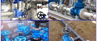
Here are the industries in which valves are used:
- city utility networks;
- oil and gas industry;
- shipbuilding;
- food and construction industry.
Almost any manufacturing and operating plant that has the smallest pipeline network needs shut-off valves. The valve is its most common representative.
What types of valves are there?
To work with different substances circulating through pipes, valves are manufactured in different designs. They differ in:
- body material;
- spindle type;
- material of sealing surfaces of the valve;
- drive type;
- method of connection to the pipe.
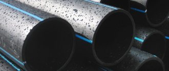
Depending on the material of the body parts, cast iron and steel valves are produced. Cast iron is designed for non-aggressive environments such as fresh water and steam. The maximum pressure in the pipe at which the valve operates under normal conditions is not high - up to 1.6 MPa (or 16 atmospheres).
Steel valves are divided into high-carbon and alloy steel products. High-carbon alloys are designed to work with water, steam, and oil products.
But valves made of alloy alloys can be used in pipelines that carry aggressive media (acids, alkalis, etc.). The maximum system pressure is up to 250 MPa.
When determining acceptable working environments, one must be guided by GOST 9.908-85g. According to this document, the corrosion rate of valve body parts during operation should not be higher than 0.1 mm/year.
According to the type of spindle, valves come with a retractable and non-retractable spindle. This classifier also affects the scope of application of the fittings. For example, valves with a non-rising spindle are installed only for clean water, steam and oils. But devices with a retractable spindle are used for a wide range of working environments.
The material of the valve seals also affects the scope of application of the valve. For municipal needs, as well as for highways where water and steam are transported, rubberized valves are used. But for petroleum products and other substances, manufacturers use steel valves with stainless steel overlay.
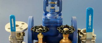
According to the type of drive, valves are:
- manual (steering wheel);
- mechanical (gearbox);
- and electric (electric motor).
Gate valve bodies are equipped with 2 types of connections - flanged and welded (welded, with cutting of connecting pipes).
Each modification of the valve has its own advantages and disadvantages, as well as scope of application.
Where are wedge valves used?
Shut-off valves with wedge elements are used on pipelines of local and main importance. Suitable for use in a wide range of temperatures, pressures and pipeline diameters - up to 565 degrees Celsius, 25 MPa and 2000 mm, respectively. Convenient for heat, gas and water supply, transportation of oil and gas on an industrial scale.
One of the application options is intra-house and transport communications (for example, the pipeline system of a ship or submarine).
The choice of an automated or manually controlled valve depends on the diameter of the pipeline, pressure in the pipes (as well as temperature) and other operational features of the communications.
Operating principle
The valve is designed to stop the flow of substance in the pipeline. The main moving part is a valve located perpendicular to the flow axis.
Valves are installed in pipelines through which they circulate
:
- water;
- steam;
- gas;
- petroleum products;
- chemical substances.
Using the steering wheel (1) and the running nut (2), the spindle (6), secured in a T-shape with the shutter (9), is driven.
The rotation of the nut is transmitted to the spindle, which, through a rotational-translational movement, opens/closes the shutter. The section on the right shows that the valve and part of the spindle are located directly in the working space, in contact with the substance circulating in the pipe. To prevent the substance from escaping into the environment, the moving part is hermetically sealed using hinged gland bolts (4).
The oil seal itself is equipped with a packing tightly wound around the smooth part of the spindle (rod), which is a seal. In addition, the seal is placed in a special groove in the flange connection of the cover (5) and the body (7).
To fix the valve, connecting flanges (8) are used, which are also sealed using a gasket - paronite.
In Fig. Figure 2 shows a steel gate valve with a rising spindle. When the steering wheel rotates, the spindle moves up, opening the shutter, for the full release of which a yoke assembly (3) is provided in the device. The height of this unit is no less than 1 nominal diameter.
Gate valves are available in different modifications.
Most Popular:
- 30h6br;
- 30s41nzh;
- 30s15nzh;
- 30s64nzh.
After manufacturing, each valve is subjected to factory testing for the strength of the body parts and the tightness of the valve.
With non-retractable spindle
In addition to the valve with a rising spindle shown in Fig. 2, devices with a non-retractable spindle are manufactured. Their main feature is their lower construction height.
Valves with a non-rising spindle are installed in cramped conditions, mainly for operation in pipelines through which water (without impurities), oil and petroleum products, and oils circulate. This type of fittings is widely used for ship construction.
The principle of operation of a non-retractable spindle is that when the steering wheel rotates, it (the spindle) makes only rotational movement. In this case, the wedge is screwed onto a spindle, which is “hidden” in a special hole (groove) formed in the body of the wedge.
Gate valves with a non-rising stem are mostly made of cast iron.
The model range is represented by the following products:
- 30h39r;
- M3B;
- M3VG.
Like steel and cast iron valves, they are subject to factory tests before sale, with the results mandatory being recorded in the product passport.
Ball valve and valve: differences and product features!
What is better to buy: a faucet or a device such as a valve? It is actually impossible to accurately answer such a question. Indeed, in some situations it is necessary to use a ball valve, but in others - a special valve. Additionally, it is recommended to note here the fact that the faucet is considered a more convenient device to use. In this situation, the handle can be rotated a full 90 degrees. Due to this, the incoming water is blocked. But the shut-off valve present in the valve must be screwed in order to close or open the water supply.
Additionally, the valve has special valves with gaskets. When they wear out, you can simply replace them with a new version. It is also recommended to periodically replace the oil seal itself. But with the ball type of valve, such problems actually do not exist. Only constant and careful care of the surface itself is recommended here. It should always be in the most ideal condition.
In general, if the water supplied to the room is really quite hard, then installing a valve is recommended. After all, such a product is subject to, although partial, repair. In a situation where the faucet is damaged for certain reasons, then it is impossible to do without its full replacement.
With all this, the valve can most often be purchased at a lower cost when compared to the second type of product. This not too high price is primarily due to the fact that the device has a simple design of an element such as a shut-off valve.
In any situation, shut-off valves are used in modern times to create a variety of sewer and gas pipeline systems. It is also often found in pipelines for general purposes. The device is intended to shut off gas or water flow. For this purpose, it is possible to install not only valves and gate valves, but also devices such as taps and valves. They all have a huge number of advantages, and some negative characteristics. It all depends on the situation.
Thus, the difference between a valve and a tap initially lies in the fact that using a tap it is impossible to regulate the pressure of the working flow. But the second product allows such an action.
Add to bookmarks
They are used on pipelines with a large diameter, more than 50 mm, where it is necessary to slowly shut off the flow to prevent water hammer.
At the valve, the valve moves perpendicularly, and at the moment of closing the sealing surfaces do not experience friction, which significantly reduces the occurrence of scoring.
Due to the fact that inside the valve body the flow direction changes twice, and the flow area is smaller than that of gate valves, the valve has increased hydraulic resistance, which is its main disadvantage.
The valve cannot be operated in different directions relative to the flow. Its working position is the direction of flow when, in a closed state, it presses on the plate from the side of the seat, and not from the side of the rod. In this position, the flow pressure when the valve opens even helps lift the plate from the seat. If the valve is installed incorrectly, the flow pressure in the closed position presses the plate, and when the valve is opened, a very significant force will have to be applied to move the rod, since it will be necessary to overcome the flow pressure. This can lead to its failure, since the shutter plate can be torn off the rod, which will require large labor costs for repair.
How to distinguish a cast iron valve from a steel one?
You can distinguish a cast iron product from a steel one by several parameters.
1. Name of the reinforcement according to the table of figures.
2. Case color.
3. Scope of application.
4. Material of the sealing surfaces of the wedge.
Let's compare the designation of steel (30s41nzh) and cast iron (30ch39r) fittings.
30s41nzh – steel valve with stainless steel sealing surfaces. The letter “c” in the designation indicates the material of the body parts. In this case, “c” is high-carbon steel. The marking “NZ” indicates stainless steel overlays. Such seals are mainly used for petroleum products, oils, gasoline, kerosene and some gases.
30ch39r – cast iron valve with a rubberized wedge. The designation “h” indicates the material of the body parts. The letter "ch" is cast iron. The marking “p” indicates that the wedge is made of rubber. Rubber-lined valves are used to transport water and steam.
The color of the body, steel and cast iron fittings are also different. Carbon steel products are painted gray. But cast iron valves can be black, red and blue.
Do not confuse the blue and light blue markings of the fittings. The blue color means that the body is made of alloy steel.
If the product passport indicates that only water and steam can be used as the working medium, this is cast iron fittings. If it can be used in pipelines through which gases, oil products and other substances circulate, this is a steel valve.
Advantages and disadvantages of valves
Valve design diagram: 1 - valve body, 2 - nut, 3 - washer, 4 - gasket, 5 - valve, 6 - seal, 7 - rod, 8 - special bushing, 9, 16 - oil seal, 10, 15 - oil seal bushing, 11 - flywheel, 12 - washer, 13 - screw, 14 - cap washer.
The main advantage of valves is that there is no need to overcome the pressure of the medium during the movement of the working element, which in turn is the force required to move the valve. Of considerable importance is the direct flow of the transported medium and the low resistance coefficient in the open state.
Due to the symmetry of the design, it is possible to use valves in different directions of movement of the transported medium, without unnecessary assembly and disassembly of flange connections when it is necessary to change the direction of movement of the internal medium.
The main disadvantage of the design is that in the process of moving the working body of the valves, strong friction occurs. Gate valves have a large construction height due to the need to extend the stem.
When the valve is located in an intermediate position, the seat section is partially blocked by the plates, the flow actively flows around the lower areas of the sealing ring surfaces, exposing them to abrasive wear by solid inclusions of the working medium. Therefore, after operation in partial closing mode, the valves do not provide sufficient tightness when they are closed. This drawback is inherent in various types of fittings and limits the use of the valve as a control element. In addition, the control characteristics of the valves are unsatisfactory.
Gate
The gate valves are represented by 3 types according to the type of formation.
1. Wedge. The sealing surfaces are at an angle to each other.
2. Disc. The seals are parallel.
3. Sheet (gate). The shutter is made of solid metal sheet.
Wedge valves are divided into designs with a rigid, elastic and double-disc wedge. Each type has its own advantages and disadvantages. For example, a rigid wedge has high tightness ratings, but the process of adjusting the geometry of the seals is difficult.
Depending on the type of sealing surfaces, there are 2 types of valves.
1. With EPDM rubber coating (shown in Fig. 3). The rubber wedge is used for installation in pipelines of utility systems. The rubberized wedge is not subject to corrosion and has excellent abrasion resistance when working in hard water.
2. With welded surfaces on the wedge and on the body rings. Stainless steel wire is used as a welding material. Stainless steel is used on lines with high pressure and temperatures up to +4250C, as well as in the chemical industry.
Figure 5 shows a valve with stainless steel overlay. A wedge (2) is attached to the rod (1) using a T-shaped connection. The housing rings (3) have a welded part that is in contact with the welded part (5) of the disks (4).
The quality of surfacing and grinding of ring and disk seals directly affects the tightness class of the valve, determined according to GOST 9544-2015. test method.
Varieties of wedge design
The choice of wedge type for a gate valve depends on the operating conditions of the device.
- Hard wedge. Features of application: for maximum tight constipation. It requires precise adjustment of the working parts (the angle of the wedge narrowing and the inclination of the seats), and can lock up due to sudden temperature changes or damage to the contact surfaces.
- Double-disk design - the lock consists of two disks that have little freedom of movement. Thanks to this, such precise adjustment of the contact surfaces of the wedge and seats is not required, and the risk of the system stopping is reduced, although the design of the mechanism is a little more complex to implement.
- The elastic wedge is a modification of the mechanism with two disks. Changing their position relative to each other is ensured by a flexible element. The self-alignment of the disks relative to the contact surface of the seats is smaller, and the mechanism as a whole is simpler.
type of drive
According to GOST 5762-2002, the valves produced are manufactured for pipelines with a bore diameter from 15 to 1600 mm. Devices with a nominal diameter of 50 to 800 mm are in demand in production.
This variation in standard sizes causes a large difference in the dimensions of each model. For example, the weight of a valve with a passage diameter of DN 50 is no more than 40 kg. But the 800 mm model weighs about 3.5 tons. Accordingly, it is inconvenient to use such a device with a manual mechanism.
Therefore, manufacturers complete valves with different drives.
There are:
- manual;
- mechanical;
- electrical;
- electromagnetic;
- pneumatic;
- hydraulically driven.
Visually, the hydraulic drive is similar to a pneumatic drive. They differ only in the control medium: the first uses liquid, the second, respectively, gas (air).
The control medium is the way the gate is influenced. In our case, it is a liquid or gas.
The most popular drives are manual, mechanical gear and electric.
Marking of models equipped with a mechanical gearbox: 30s564nzh, 30s527nzh. The number “5” indicates the type of drive – gearbox.
Models on which an electric drive is installed are marked with the number “9”. For example: 30s964nzh, 30s941nzh.
Cast iron fittings are marked in a similar way. Example: 30h906br.
Electric drives are also installed on small diameter valves. This is due to the length of the pipeline systems. In this case, the highway is divided into sections controlled by a single remote control.
When installing an electric drive, you must be guided by the type of drive connection specified in GOST R 55510-2013. The product data sheet indicates the maximum torque. It is individual for each model. Failure to comply with these requirements may result in damage to the wedge or leakage of the operating fluid into the atmosphere.
Valve valve design and operation
The most important working part of the valve is the seat with a shutter moved manually by a spindle. The water valve, the design of which is shown below, contains threads in the body and on the stem, which have the property of braking. As a result, the valve disc is pressed tightly against the seat, shutting off flow when the valve is closed. In the open state, the flow area remains unchanged when the water flow moves.
Typically, the body is not threaded because it wears out quickly. To do this, a running nut is attached to it, into which the spindle is screwed. Then, instead of the worn-out unit, you can install another one, and the housing will be preserved. All parts are interchangeable with a water valve (GOST 12.2.063-81, GOST 5761-74).
The valve is opened by turning the handle. At the same time, the spindle moves progressively, freeing up the passage for liquid. If the rotation is performed in the opposite direction, the valve will close.
The device is connected to the pipeline through the inlet and outlet pipes. They can be distinguished from each other by the presence of an arrow indicating the direction of flow.
Housing material
Body parts of valves, which include the body, cover and steering wheel, can be made from;
- cast iron grade GGG40;
- steel grade 25/35L;
- alloy steel 20GL;
stainless steel grades 20Х5МЛ, 12Х18Н9ТЛ or 12Х18Н12М3ТЛ.
Each metal has its own individual strength characteristics and structure.
Cast iron
Cast iron bodies are cast for fittings used in municipal systems, for heating and water supply, mainly for water and steam. Additionally, the body is coated with an epoxy powder composition.
GGG40 cast iron is a high-strength cast iron whose crystal lattice contains spheroidal graphite, which has a lower surface-to-volume ratio. This factor has a positive effect on the continuity of the metal, which becomes more resistant to corrosion.
Continuity is the property of a metal to fill the entire space (volume) without voids or defects. The higher the continuity, the better the quality of the alloy.
Treatment of the internal cavities and outer body of a cast iron valve with an epoxy powder composition increases corrosion resistance, significantly increasing its service life.
Some valve models are treated with nickel plating.
Nickel plating is the process of applying a layer of nickel to the surface. The layer thickness is 50 microns.
The nickel layer protects the metal from corrosive destruction, extending the service life of the product.
Steel
Steel bodies made of 25/35L are wide-profile. They are successfully used both for water/steam and for oil and gas pipelines, nuclear power plant and energy systems.
Alloy 25L is widely used in mechanical engineering. Bearing housings, pistons and cylinder covers are made from it. The operating temperature range for 25L is from -400C to +4500C. The use of alloy 25L for valves is an indicator of strength and reliability.
The production of housings from alloy and stainless steel is carried out for pipelines operated in cold regions (temperatures up to -600C), as well as for highly aggressive environments. Such valves are manufactured to order from a specific production facility.
Pressure, flow and level regulators
Figure 7. Pressure regulator with connecting flanges
Purpose of regulators
Regulators (reducers) of pressure, flow and level are designed to automatically maintain the corresponding parameter without the use of secondary energy sources.
Regulator design
The design of the regulator is a valve with a pneumatic or hydraulic actuator of a membrane, bellows or plunger type, as well as a special installation spring designed to adjust the regulator to the required parameter value. The designs of regulators are extremely diverse.
Level regulators are divided into:
- supply regulators, in which the level is maintained by periodically adding liquid to the vessel, and
- overflow regulators, in which excess liquid is drained.
Pressure regulator
Consider a pressure regulator
using the example of a gas cylinder reducer. The opening of the gas inlet pipe is the valve seat, against which the valve plate attached to one end of the angle lever is pressed. The second end of the lever is connected to a movable membrane, which is acted on from the outside by the force of atmospheric pressure and the compression force of the installation spring, and on the other side by the force of gas pressure in the cavity of the regulator. The axis of rotation of the lever is fixed to the bottom of the regulator body. If the pressure of one of the burners of the gas stove is closed, the gas flow will decrease, as a result of which the gas pressure in the reducer cavity will begin to increase. This will cause the membrane to move, which will pull the end of the lever connected to it. The second end of the lever with the valves attached to it will also move and cover the hole for the passage of gas. As a result, the gas pressure in the reducer cavity will be at an almost constant level, since the valve stroke is extremely small and the force of the installation spring will change slightly when the membrane moves.
The regulator will ensure that the required gas flow is passed at a constant pressure value in front of the burners.
Flow regulator
Figure 7. Direct-acting flow regulator with connecting flanges.
Flow regulator is working
similar to a level regulator, maintaining a constant differential pressure across some throttling device, such as a diaphragm or adjustable nozzle. Since the local resistance coefficient of the throttling device does not change, a constant pressure drop means that the flow rate through the throttling device is constant and therefore the flow rate is constant. Some regulators have a throttle, the design of which allows you to adjust its resistance, adjusting the regulator to the required flow rate. More often, however, the resistance of the throttling device is left constant, and the compression of the set spring is changed, which allows the pressure drop across the throttle and, consequently, the flow through the regulator to be adjusted.
In regulators, an important principle is to unload the valve from the one-sided pressure of the working medium, which can significantly reduce the effort required to move the working element. The most perfect type of unloading is a double-seat valve design, when the forces acting on two plates are opposite in direction and mutually compensated. However, in this housing design it is more difficult to manufacture the housing and it is more difficult to ensure that two valves are completely sealed at the same time. Despite such difficulties, this design is very widely used in modern regulators.
Nut and spindle material
High demands are placed on drive parts. For example, one end of the spindle is in the working environment, and the other is a member of a threaded pair, where it is affected by friction.
The spindle is made of steel:
- 20Х13;
- 14Х17Н2;
- 12Х18Н9Т.
The increased chromium content ensures normal operation of the reinforcement under difficult conditions with constant friction.
The requirements for the drive nut are lower since it is not affected by the operating environment. LS59-1 brass, which is resistant to friction, is used here. For cold regions, nuts are made of 40X steel.
In some models, the spindle is made of bronze BrAZhMts10-3-1.5.
Design differences
You can often come across the phrase “valve valve”. But in fact, there is a difference between a gate valve and a valve in the design and operating principle of the shut-off element. Thus, in a valve, in most cases, the lumen of the pipeline is blocked by a wedge, which moves perpendicular to the flow of the working medium. And at the valve, the shutter is made in the form of a cone or disk (spool) moving parallel to the flow. When closing the valve, the shutter moves against the flow of the medium; when opening, it moves vice versa.
In order for any pipeline shut-off mechanism to work, an appropriate structure of the valve body is necessary. The valve has a cylindrical body, the medium moves straight through it. When the device is open, the flow may be slightly obstructed by the narrowing of the lumen and the presence of o-rings in it (they ensure a tight fit of the wedge when the valve is closed). This design is characterized by low hydraulic resistance.
The valve body is much more complex. In it, the flow of the medium makes two successive turns at right angles. This creates a lot of resistance when the valve is raised and significantly reduces the flow rate. But when closing and opening a shut-off valve, the shutter moves only 0.25 DN, and for gate valves it must be moved to the full diameter. Because of this, the valves have a much higher construction height.
Briefly the main design features of the valve and gate valve are given in the table:
| Constructive | Gate valve | Valve |
| Hull structure | The body is simple cylindrical (full bore or narrowed), the medium flow moves straight | Housing with a complex internal design, thanks to which the flow turns 90° twice |
| Gate | Wedge, gate | Spool, cone-shaped valve |
| Direction of movement of the locking element | Perpendicular to flow | Parallel to the flow |
| Types of connections to the pipeline | Flanged, socket, welded | |
| Control methods | Manual (flywheel), using a mechanical gearbox, drive mechanisms (force is transmitted to the valve through a threaded pair) | |
Functional differences: advantages and disadvantages
How does a gate valve differ from a valve in terms of operation? Let's start with the fact that these two types of fittings have a lot in common:
- Variety of material designs. This allows you to select a gate valve or valve for any working environment.
- Both gate valves and shut-off valves are available with different methods of connection to the pipeline. They are convenient to install into the system.
- Both types of devices provide high tightness of the overlap. They are used only to completely shut off the flow and cannot serve as control valves (except for special models).
At the same time, valves and valves have their pros and cons. For clarity, we have collected them in a table:
| Gate valve | Valve |
| – Large valve stroke for full opening (1 nominal diameter), therefore, it takes a long time to open and close the valve | + Small valve stroke for full opening (up to 0.25 nominal diameter), so the valve can be opened or closed faster than a gate valve |
| + Low hydraulic resistance (for full bore valves it is practically absent) | – High hydraulic resistance due to complex housing design |
| + Absence of stagnant zones, which allows the use of valves with thick, viscous, contaminated media | – The presence of stagnant zones in the design of the shut-off valve limits its scope of application, since with some media this feature can cause accelerated corrosion |
| – It is more difficult to ensure high tightness of the overlap during the manufacture of fittings | + It is easier to ensure the required tightness of the valve |
| – Friction when closing and opening the valve gradually leads to wear of the sealing surfaces of the wedge and body | + There is virtually no friction when the bolt is seated |
| – To seal the valves with respect to the external environment, seals are used | + Gland or bellows seal possible |
| – Valves are installed only on straight sections of the pipeline | + There are straight-through and angle shut-off valves. Angled ones can be installed in places where pipelines turn 90° |
| – The direction of movement of the medium during installation does not matter | + During installation, the fittings should be installed so that the arrow on the body coincides with the direction of the medium flow |
| + Possibility of using valves on pipelines with large diameters. Above 30mm in diameter they work more efficiently than valves | – Diameter limitation (with a large nominal diameter, the operation of the valve becomes much more complicated; a powerful flow of medium prevents the valve from properly seating in the seat) |
| – Large construction height and weight | + Low construction height, less weight than a gate valve |
| + Short face-to-face length | – Face-to-face length is approximately 1.5 times greater than that of a valve of similar DN |
Thus, there are fundamental differences between a valve and a gate valve that affect the scope of their application and the process of operation.
Gate
In cast iron valves, ethylene-propylene rubber (EPDM, VITON, Silicon) is used as a wedge seal. The wedge body is cast from GGG40/50 cast iron. To improve the wedge's resistance to corrosion, a layer of nickel is applied to its surface.
In steel reinforcement, the requirements for the wedge and discs are higher than in cast iron products. Therefore, they are made from steel grades 25L, 20GL, or from alloys containing stainless chromium and nickel additives (for use in severe climatic conditions).
Surfacing on the sealing parts of the body rings is carried out using corrosion-resistant wire:
- 07Х25Н13;
- 08Х21Н10Г6.
Since surfacing occurs at high temperatures (up to 35000C), the surfacing wire contains certain additives that help preserve the crystal lattice of metals.
Wedge seals are fused with steel 13Х25Т, or 10Х17Т.
These alloys contain nickel, chromium, titanium and copper. Due to these metals, the deposited surfaces have excellent strength, toughness, abrasion resistance and corrosion resistance.
Cranes: main characteristics
A faucet differs from a valve and gate valve in that to start or stop the flow using a faucet, it is not necessary to rotate the spindle
They do not have a rod, and their valve is made in the shape of a ball, cone or cylinder with a hole for the passage of flow and rotates perpendicular to the flow. If the axis of the valve hole coincides with the axis of the pipeline, then the valve is open, since the flow passes through the hole. If the shutter is turned 90°, the valve will be closed. A faucet differs from a valve and gate valve in that to start or stop the flow using a faucet, it is not necessary to rotate the spindle. To do this, just turn the shutter 90°. This differs from a valve to a valve. It does not have a flywheel, so it is operated by a crank. The valve is in the open state if the handle is located along the pipeline, and if it is perpendicular, it is closed.
In cone valves, the valve is made as a truncated cone. It has a hole for the passage of flow in the form of a rectangle or circle. The valve body also has a conical surface. This was done so that the plug could fit tightly to the saddle.
For tightness, the seal is sealed with lubricant, which should fill all micro-gaps between the body and the shutter. At the same time, it reduces the force required to turn. The cork is pressed against the surface of the body.
There are two ways to press the valve, and therefore a distinction is made between stuffing box and tension valves. In gland valves, between the upper end of the plug and the valve cover there is a gland packing. This is an elastic element that presses the valve to the body with constant force. Tension taps have a rod at the bottom of the plug that passes through the body hole. The shutter is pressed by a spring. Such taps are more reliable, since they do not have gland packing, the elastic properties of which are lost over time. Therefore, in such important industries as gas supply, tension cranes are used.
Cone valves are low cost, they are not difficult to inspect, they have a simple design and relatively low hydraulic resistance. This is their advantage
But such cranes also have disadvantages. It takes a lot of force to turn the plug. Over time, the microgaps between the shutter and the body surface become covered with deposits. In this case, turning the valve requires a lot of force, which can lead to breakage of the valve.
The production of taps requires a high-quality processed surface of the valve and body, so they are made of bronze and brass. In addition, these metals are less susceptible to corrosion, which extends its service life.
Almost no pipeline system is complete without critical elements designed to shut off or control the flow of fluid within it. In domestic conditions, valves are usually used for these purposes. Valves and gate valves are larger devices that are used on large utility lines. There is a lot in common between them, but, nevertheless, these are different elements that differ from each other functionally and have a different structural structure.
Gland packing
Basically, in modern valve manufacturing plants, TRG rings are used as gland seals.
TRG is thermally expanded graphite reinforced with various materials.
TRG is used as a reinforcing agent:
- stainless steel wire;
- cotton thread;
- fiberglass;
- lavsan;
- Inconel wire.
Also, AGI asbestos cord is used to seal the oil seal. It is impregnated with special graphite.
The use of one or another sealant determines the industry of use of the fittings. For example, when sealing TRGs reinforced with stainless steel wire, it is allowed to operate the valves in aggressive environments of the chemical industry.
Diameters and dimensions
The overall and installation dimensions of wedge valves are determined by GOSTs and TUs and differ for products made from different materials for different purposes. So, for products 30ch925brM and 30ch39r the parameters are given in the table.
The model range of wedge gate valves includes products with a nominal diameter (nominal diameter of the passage opening) of 15...2000 mm.
Flange seals
The valves are mounted in the pipeline using a flange connection. In addition to this method, a welded connection is used. But the flange is more common.
To ensure an exact match between the holes of the flanges of the fittings and the pipe, they are made to match. The process is regulated by GOST 33259-2015.
The fastening of dimensional fittings into the pipeline occurs using lifting structures (gantry, portal or other cranes). In order not to damage the body parts, the slings are installed in the places specified in the operating instructions for the specific model.
The valve and pipe flanges have grooves. They are needed for laying the sealant - paronite.
Paronite can be used in 4 types:
- ordinary (general purpose);
- reinforced (holds high pressure);
- oil-gasoline resistant (for oil, liquid gas);
- electrolysis (for acids).
The valve body and cover are also connected by a flange and have corresponding counter grooves. The specific seal gasket is selected for each application.
Main parameters of valves
Gate valves are produced for specific operating conditions and are divided into:
- nominal diameter DN;
- nominal pressure PN;
- climatic design;
- maximum temperature of the working environment;
- spatial location in the pipeline;
- seal tightness class.
The nominal diameter is the diameter of the nominal diameter measured in the valve. Gate valves can be produced as full bore or partial bore. The second option means that the diameter in the valve will be smaller than the diameter of the pipe for which the valve is intended.
Nominal pressure is the maximum pressure in the line at which the valve will operate normally according to the tightness class stated in the passport. Note that the nominal pressure value indicated in the passport determines the maximum pressure of the working medium at its temperature of 200C.
Climatic performance
This parameter characterizes the maximum ambient temperature at which the valve can be operated.
1. T1 – from -100С to +500С.
2. ТпУ1 – from -290С to +400С.
3. U1 – from -400С to +400С.
4. HL1 – from -600С to +400С.
Climatic design is classified according to GOST 15150-69.
Maximum operating temperature
For valves whose bodies are made of stainless steel, the temperature limits of the media are wider than for steel and cast iron.
For stainless steel cases the temperature range is from -400C to +5500C. For steel products – from -10 to +4250С.
But for cast iron these figures are significantly lower:
- from -50С to +900С when using an EPDM shutter;
- from -50C to +1500C when using VITON and Silicon shutters.
Operation of valves at maximum temperature is carried out with a mandatory reduction in the pressure of the working medium. This is due to a decrease in the strength of body parts.
Location in pipeline
Basically, cast iron and steel valves are designed to operate in a vertical spindle position. When installed in a pipeline, it is allowed to place the fittings with a deviation of up to 90 degrees in any direction. The location requirements of the drive must be taken into account.
There are no spatial restrictions for manual and mechanical drives. But for an electric drive, pneumatic or hydraulic, manufacturers can set restrictions that are indicated in the product passport.
When installing valves of large diameter (from 400 mm), as well as those equipped with an electric drive, it is additionally necessary to provide support for the drive (when installed with a deviation of up to 90 degrees).
Support is also necessary for the valve if the pipeline in this place is not reinforced.
Structural features
The difference between the elements lies in the design of the locking elements: for a gate valve it is a wedge, gate or parallel lock of one or two disks, which moves perpendicular to the flow, closing the passage hole; for a valve, it is a valve with a threaded spindle.
Gate valve
A valve is a part for blocking a passage opening. There are gate, hose and parallel, which is due to the design feature.
Gate valve elements:
- body made of cast iron, steel, brass,
- housing cover made of the same material as the housing,
- constipation (wedge, gate, discs),
- spindle (threaded rod) retractable or rotatable,
- flywheel or gear drive (for automatic control).
In pipelines, full bore devices are most often installed, in which the diameter of the bore is equal to the diameter of the pipe, but in some cases narrowed valves are used to reduce wear on the seals.
Valves work more efficiently on large pipelines, where the pipe diameter is above 300 mm and the pressure level is increased. The valve is devoid of bends and therefore does not create unnecessary resistance. One-sided pressure presses the valve tightly against the seat, so the device is more reliable and durable.
Valve
A shut-off device for systems for various purposes, in which the passage hole is closed using a valve.
Design elements:
- the valve body can be made of cast iron, steel, bronze;
- shut-off valve seat;
- the valve itself with a threaded spindle;
- rotation handle
A valve is used as a shut-off element, which is adjacent to the seat parallel to the movement of the working medium and divides its flow at a right angle, narrowing the passage holes. In this case, the resistance only increases, which creates additional mechanical load on the shut-off valves.
Leakage class
Before you buy a batch of valves, you need to select the required valve tightness class. At factories, this parameter is determined by pilot (acceptance) tests on special installations.
The testing procedure and tightness class are determined by GOST 9544-2015. According to this document, valves are tested with liquid or gas.
- If the valve will be installed in a pipeline for transporting liquid and non-hazardous substances, tests can be carried out with liquid (water, kerosene).
- When installed on pipelines in which the working medium is gas or a hazardous chemical, tests are carried out only with gas (air, nitrogen).
- In each specific case, by agreement between the plant and the customer, tests can be carried out with liquid and gas, only gas or only liquid.
Test requirements for liquid and gas are different. So, when water is supplied to the pipe, its pressure rises to the PN mark indicated in the passport for the valve and increases by 10%. The valve is kept in this state for some time and the leakage volume is measured.
The start time for leakage measurement after steady pressure is different for each valve.
1. For DN up to 50mm, the holding time is 1 minute.
2. DN from 65mm to 150mm – 2 minutes.
3. For DN from 200mm and more – 3 minutes.
These standards apply to both water and air tests. For air, the pressure in the system is increased to 0.6 MPa, regardless of the diameter of the passage.
The manufactured fittings can have a tightness class from A to G. Class A is the highest and is assigned to fittings that have absolutely no leaks in the valve.
Manufacturers and average prices
Among the manufacturers we can distinguish the following domestic and foreign companies (near abroad):
- Agrokomplekt, JSC (Russia, Podolsk);
- Armalit, OJSC (Russia, St. Petersburg);
- Blagoveshchensk Reinforcement Plant, JSC (Russia, Blagoveshchensk);
- Budava, JSC (Lithuania, Kaunis);
- Pipeline Elements Plant, JSC (Russia, Bolshoi Istok);
- Ivano-Frankivsk Reinforcement Plant, JSC (Ukraine, Ivano-Frankovsk);
- IKAR, Kurgan Pipeline Fittings Plant, LLC (Russia, Kurgan);
- InterArm, group of companies (Russia, Moscow).
For gate valves made of ferrous metals, the price index for the indicated manufacturers is 1.9777 rubles/+12.90% (according to Infogeo.ru).
For foreign manufacturers (Tecofi, HAWLE, BRANDONI, UKSPAR and others) prices range from 800...170,000 rubles, depending on the brand, characteristics and purpose of the product.
Installation
Since pipelines operate under high pressure, an installer’s mistake will result in casualties. Therefore, the installation of valves should only be carried out by trained personnel who have access and permission to carry out this type of work.
Before installation you must:
- carry out re-preservation, in compliance with the requirements of GOST 9.014-78;
- lubricate the spindle with special lubricant;
- remove the factory plugs from the pipe;
- check the cavities of the pipes for the presence of foreign objects and dirt;
- Check the operation of the shutter by opening and closing it.
Installation into the main line is carried out using lifting mechanisms (cranes). The valve can only be hung by the pipes or using the method specified in the operating instructions.
It is necessary to re-preserve the fittings immediately before installation.
When supplying the valve to the pipeline, its collision with the connecting pipes is not allowed. The hangers can be removed only after installing all bolts, nuts and studs in the flange holes (or after completing welding work). Failure to comply with this point will lead to misalignment of the flange connection and loss of tightness.
Bolts and nuts are tightened using a special torque wrench with a built-in dynamometer. This device ensures that the fasteners are tightened with the required forces, avoiding overtightening.
Features of choosing shut-off valves
For reliable service of the valve, it is necessary to select its model in accordance with the specified operational characteristics.
It is necessary to determine:
- planned operating conditions – properties of the serviced working flow: temperature, pressure, corrosion properties;
- throughput;
- required level of tightness;
- size of connecting flanges, method of connection to the pipeline;
- dimensions and design of the case;
- method of controlling the valve (manual or using an electric, hydraulic, or pneumatic drive);
- safety requirements: explosion-proof, ability to withstand hydraulic shocks.
Tests
After installation of the fittings, hydraulic tests (pressure testing) are carried out. This procedure is carried out with a working medium, increasing the maximum pressure by 25%.
During crimping, the following are checked:
- tight connection between valve flanges and pipeline;
- tightness of the gasket connection between the body and the cover;
- tightness of the stuffing box seal.
Pressure testing is carried out with a mandatory open passage. Moving the valve when the test pressure is reached is not allowed.
The results of hydraulic tests are entered into the product passport.
GOSTs and technical specifications
Technical requirements and standards relating to the manufacture, design, operation of wedge valves and other shut-off valves are set out in the following regulatory documents.
GOSTs of the USSR period
And:
GOST 5762—2002. Industrial pipeline fittings. Valves with a nominal pressure of no more than PN 250.
Regulatory documents define the following technical characteristics of valves:
Storage
If, after purchasing a batch of fittings, there are no plans to install it in the main line in the near future, or the removed valve needs to be removed for long-term storage, conservation measures are carried out.
The procedure for conservation is specified in GOST 9.014-78. The device must be stored in its original packaging with the pipes cleaned of any remaining media and plugged. The spindle must be lubricated with special grease VNIINP-232.
The shutter must be closed during storage.
Transportation of preserved fittings is carried out in original packaging. The boxes must be secured with transportation fasteners that do not allow longitudinal and transverse displacements during movement. Loading and unloading operations are carried out without shocks or impacts.