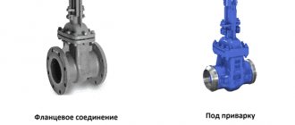
Unlike household communications with ball valves and valves, the problem of shutting off the flow of the working medium in industrial pipelines is solved through the use of special shut-off valves. One of the most popular and frequently used devices for these purposes is a wedge valve.
This type of fittings has different design options and materials of manufacture. In order not to make a mistake in choosing suitable devices, it is useful to study their areas of use, types, operating principles, and technical parameters of wedge valves.
Rice. 1 Examples of valve placement
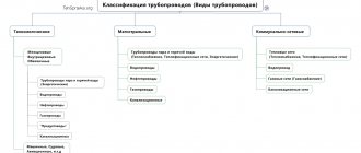
Valves classification
In order to meet the technological needs of the entire pipeline industry, valves are produced with different technical characteristics and for different purposes. They differ in:
- designs;
- drive type;
- material of manufacture;
- connecting dimensions;
- connection type;
- operating temperature;
- the type of substance transported in the pipe;
- climatic design;
- tightness class;
- wedge designs;
- bore diameter;
- indicator of maximum pressure in the system;
- type of sealing surfaces of the valve;
- type of seals of the cover and stuffing box.
As you can see from the list above, valves have a wide range of characteristics. To simplify the selection of a product for a specific production with all its features, a uniform procedure for marking shut-off valves has been established. It is indicated in the document ST TsKBA 036-2017.
In addition, manufacturing plants additionally equip valves with information plates reflecting the main technical and operational characteristics of the product. In the following sections, sufficient attention will be paid to notation. But first, let's get acquainted with the design of the valve and its principle of operation.
Areas of application
Wedge valves are installed at the end of the pipeline and in areas where the movement of the medium is blocked in order to carry out emergency and technical work. Such parts have a wide range of diameters and operating pressures, as they are used in various pipeline systems.
Valves, which have elastic wedge-shaped valves, are designed for high-speed flows and can work with high-pressure media. They are suitable for gas and oil industries. In addition, these types of products are used at chemical plants that have lines for transporting aggressive solutions.
In water supply and heat supply systems, a wedge-shaped gate valve of the dividing type is used. For such products, the shutter has 2 parts so that the displacement area increases. Due to this, thermal expansion is compensated. Similar products are also used on steam lines.
Design
The valve consists of 3 main parts.
- Drive with drive mechanism.
- Cover with stuffing box.
- Housing with pipes.
Figure 1. Design
Figure 1 shows two types of valves:
- with retractable;
- and a non-retractable spindle.
The difference between these two types of shut-off valves is as follows.
In the first version, the spindle, when the shutter is raised to the “open” position, moves up, providing the required wedge stroke. This design has both advantages and disadvantages. An advantage is the fact that the spindle does not come into contact with the working environment, and therefore is not subject to corrosion. But due to the increased construction height, such a valve is not suitable for all installation conditions.
The second option does not have the disadvantage of a retractable spindle. This valve can be installed in cramped conditions. But here the spindle is located inside the housing, which means that during operation it will be affected by the working environment.
Figure 1 shows designs of manually operated valves.
But in addition to this design, devices are produced equipped with:
- mechanical gearbox;
- electric drive;
- pneumatic drive;
- hydraulic drive.
Figure 2. Types of drives
The most popular are valves with manual, mechanical and electric drives. This is explained by the fact that such devices are the most reliable and durable in operation. The use of pneumatic and hydraulic drives is very rare, since servicing tanks with liquid or air under pressure requires additional costs.
Purpose
Gate valves are a type of pipeline fittings with a locking (regulating) element that moves perpendicular to the axis of the flow of the working medium. Valves
– two-position valves. They can only be used to turn pipelines on or off. The use of valves as control devices is prohibited.
Valves are installed on both horizontal and vertical pipelines. It is advisable to install valves with a built-in electric drive on horizontal sections of pipelines with the spindle up. Where valves are installed, free access must be provided for their maintenance and repair without cutting out from the pipeline, for installation and dismantling.
Gate valves are available with wedge and parallel type gates. The valves are mainly equipped with wedge type gates. A feature of valves of this type is the dependence of the force of pressing the working surfaces of the gate on the working surfaces of the seats on the force on the actuator.
Principle of operation
Let's look at the operating principle of a valve with a sliding spindle.
In order to move the shutter to one of the extreme positions (open/closed), you need to turn the steering wheel clockwise or counterclockwise. Rotation is transmitted to a drive nut located in the center of the flywheel.
Due to the threaded connection of the nut with the spindle, the latter performs a rotational-translational movement, dragging the bolt along with it. The wedge and the spindle are connected to each other by a T-shaped joint of the tongue-and-groove type. When the shutter reaches one of the extreme positions, the movement of the steering wheel becomes sharply difficult, signaling a full cycle of operation.
Non-rising stem valves operate differently. From the name it is already clear that the spindle here does not move up/down, but only rotates around its axis. The drive nut in such a device is located directly in the wedge, secured to it with a similar T-shaped connection.
When the steering wheel rotates, movement is transmitted from the spindle to the nut. It (the nut) screws onto the spindle axis, dragging the bolt along with it. In order for the spindle to have “where to go,” a hole is formed in the wedge.
Figure 3. Shutter design
Non-rising stem valves have a limited range of applications. They are used in pipelines that transport light petroleum products, oils, as well as water with a low content of salts of alkaline earth metals calcium and magnesium (soft water).
Parallel (gate)
In gate valve devices, the surfaces of the seats and the gate disk are parallel; when lowered, the disk (gate) seals the passage due to the pressure of the conductive medium on its surface. The disadvantages include high energy consumption for movement as a result of friction of the sealing rings of the seat and gate along the entire path of movement and, accordingly, increased abrasion of the sealing surfaces. Used with reduced requirements for tightness, easy to maintain and repair.
Fig. 10 Parallel gate valves
Manufacturing materials
For comparison, let’s look at 2 popular valve brands 30s41nzh and 30ch39r.
Steel valves
The 30s41nzh case is made of steel, as indicated by the letter “c” in the marking. The prefix “NZh” at the end means that the sealing surfaces of the wedge discs and body seats are made of stainless steel.
Figure 4. Shutter 30s41nzh
But what grades of steel are the remaining parts made from:
- The lid and body 30s41nzh are cast from 25L. The letter “L” in the brand indicates that it is cast steel, and the numerical value “25” indicates the content of 0.25% carbon in the alloy.
- The spindle is made of 20X13. This steel contains 14% chromium, which makes it possible to classify this alloy as corrosion-resistant (stainless steel). 20X13 belongs to the martensitic class with operating temperatures up to 6000C.
- Wedge discs and flywheel are cast from 25L.
- Spindle drive nut – LS59-1 (brass). This alloy is a copper-zinc alloy with the addition of 1% lead. Thanks to this chemical composition, the 30s41nzh drive nut is not subject to mechanical damage due to friction for a long time.
- Nuts, studs and flange bolts are made from 35 steel. The high carbon content (0.35%) makes this alloy an excellent material for parts requiring precision machining.
- The sealing surfaces on the 30s41nzh wedge are made of 13X25T stainless steel. This steel with a high chromium content (up to 30%) provides excellent wear resistance. The alloy contains 0.5% titanium, which increases the service life of the shutter.
- The seals on the housing rings are made of stainless steel 08Х21Н10Г6. The chemical composition contains 10% nickel and 20% chromium. This alloy content provides high resistance to corrosion.
Oil seal
In addition to metal parts, the 30s41nzh valve contains an stuffing box seal in the form of a TRG packing. This material prevents the working fluid from escaping through the oil seal at the point where the spindle enters the housing.
Figure 5. Types of packing
TRG is thermally expanded graphite. It comes in the form of a cord or a ring. Several modifications of it can be used in pipeline fittings.
Here's what we're talking about:
- TRG-100L. This stuffing is reinforced with lavsan thread. There is also a modification TRG-100LF, additionally impregnated with a mixture containing fluoroplastic.
- TRG-101N. Here, stainless steel wire is used as a reinforcing material.
- TRG-102S. Reinforcement material – glass fiber.
Steel wedge valves are produced by the Siberian pipeline fittings plant SibZTA. Modern materials are used in the manufacturing process. One of them, thermoplastic graphite, is used in the stuffing box to seal the system against the environment. The addition of thermoplastics to the composition allows the packing to repeatedly transform into a viscous-flowing and highly elastic state. This means that under the influence of high temperatures of the working environment, the seal does not change its quality characteristics.
Cast iron valves
Model 30ch39r is made of cast iron grades GGG40 and GGG50. The use of this metal allows the valve body parts to withstand burst pressures of up to 370 MPa.
Unlike steel products, it is intended exclusively for use in pipelines through which hot/cold water and steam are transported.
Materials for manufacturing parts.
- The body, cover, and wedge are GGG40/50.
- The spindle is made from 20X13 or an analogue of 2Cr13.
- The seal on the wedge is EPDM.
- The bushing on the spindle is made of bronze or brass.
EPDM is the international marking of ethylene-propylene rubber. In addition to this seal, Viton (fluorine rubber) or Silicon (organosilicon compound) are used. The first has excellent resistance to highly acidic environments, while the second copes well with extreme and rapidly changing temperatures.
The main difference between cast iron valves and steel ones, in addition to the metal body, is the use of a rubber wedge (EPDM, Viton or Silicon). For water, this design is the best, since corrosion of the valve is completely eliminated.
Drive part
The drive part of the valve includes a nut and a spindle. The requirements for these components are increased. This is due to the interaction of the spindle (its smooth part) with the working environment, as well as its friction against the nut.
The nut is made from a brass rod (circle) brand LS59-1. This alloy contains:
- up to 42% zinc;
- 57% copper;
- up to 1.9% lead.
Lead increases anti-friction properties and improves workpiece machinability. Manufacturing a drive nut comes down to 3 steps.
1. Cutting a workpiece to specific dimensions from a rod.
2. Drilling a hole on a machine.
3. Milling internal threads.
The valve spindle is also made from rod, but I use a different alloy. 20X13 is used here. This metal belongs to the corrosion-resistant, heat-resistant class – ferritic-martensitic.
Rice. 3
The composition contains up to 14% chromium. Parts made from this alloy can operate in normal mode at temperatures up to +7000C without changing their physical properties.
The technology for manufacturing a spindle from 20X13 steel is similar to the process with a nut. The exception is threads that are rolled along the surface of the spindle. Accordingly, there is no drilling of the hole here.
Factories supply valves equipped with a spindle with different threads.
Wedge design
The valve design in steel and cast iron valves is different. This is due to the scope of application of the devices in the pipeline industry.
Figure 6. Types of wedge
Steel valves
Steel valves are used in highways intended for transportation of:
- hot/cold water in housing and communal services systems;
- petroleum products;
- natural gas;
- chemical substances;
- steam in heating systems and boiler rooms;
- in exceptional cases for sea water and raw materials at processing plants.
The impact of working media on the sealing surfaces of the valve causes mechanical damage and corrosion. To reduce negative consequences and increase the service life of the product, sealing surfaces are fused using corrosion-resistant wire of grades 08Х21Н10Г6 and 13Х25Т.
There are two methods of applying sealant to the wedge discs and body seats.
- Using arc welding.
- Using laser cladding.
Figure 7. Laser cladding
Both methods characterize a chemical reaction in which, under the influence of high temperature, wire from a certain grade of alloy is mixed into the base metal of the wedge (or ring). After the surfacing weld has cooled and gained strength, it is subjected to manual or automatic scraping.
Scraping is the process of creating perfectly smooth geometric parameters of surfaces. This procedure is carried out both with the wedge and with the rings in the body. The purpose of scraping is to perfectly fit two surfaces relative to each other. The main operational indicator of the valve operation – the tightness class of the valve – depends on this.
The gate wedge in steel gate valves can have 3 types of design.
- Cast all-metal.
- Double-disc team.
- The team is elastic.
In terms of performance characteristics, the best wedge design is a double-disc design. With this assembly method, it is much easier to adjust the disc and ring seals. This has a positive effect on the degree of tightness of the shutter.
Double-disc valves retain their factory tightness class longer during operation due to reduced friction of the seals. They are also less susceptible to jamming and “welding” due to corrosive destruction of the metal.
Cast iron valves with rubber wedge
The wedge of the cast iron valve is made of special EPDM rubber. Due to the physical and chemical properties of this material, during operation the valve is practically not subject to any defects or damage.
EPDM is not subject to corrosion and retains its original geometric parameters under the influence of high/low water temperatures. The addition of rubber to the sealant makes the 30x39r wedge elastic and at the same time soft.
Valves 30ch39r using EPDM as a sealant material are commonly called valves with a rubber wedge.
30ch39r is used exclusively for water and steam in urban water supply, sewerage and heating systems, as well as in enterprises operating such pipelines.
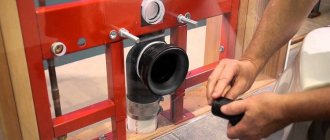
Equipment installation
The installation of valves on main pipeline systems in industry is carried out exclusively by a team of specialists. The most commonly used connecting elements are various flange connections. When carrying out all necessary work, you should adhere to the following basic rules:
- Equipment can be dismantled only after the working medium has completely drained from the system. If necessary, individual areas should be protected from plaque, scale or dirt.
- The quality of flange connections must be checked before installation. The washer itself should not have any visible damage - defects, gouges, scratches or cracks.
- Such equipment can be placed exclusively in a straight line on the main part of the highway, on previously cleaned and prepared flat surface areas. This will eliminate the possible occurrence of stress in individual areas of distortions and bends, which can lead to the formation of leaks. Rigid supports are used during the installation process as additional support.
- It is prohibited to apply pressure on the flywheels, since it is thanks to them that the valves are manipulated. Neglecting this requirement will inevitably lead to the formation of cracks and further breakdowns.
Strapping with a soft sling is mandatory, but it is recommended to avoid fastening to the steering wheel or stem, as there is a risk of damaging the protective coating. This can lead to the onset of premature corrosion.
All characteristics of the selected model of shut-off equipment must coincide with the requirements specified in GOST.
Operational performance indicators
Regardless of the valve models, general performance indicators have been established. These include:
- bore diameter du - the indicator varies from 50mm to 1200mm;
- nominal pressure pn – from 10 to 40 atmospheres (1.0-4.0 MPa);
- seal tightness class - A, AA, B, C, established in accordance with the provisions of GOST 9544-2015;
- type of connection to the pipe - welding or flange connection, made in accordance with GOST 33259-2015;
- ambient temperature indicators in accordance with the climatic design, which is determined according to GOST 15150-69;
- lower and upper limits of the working environment temperature depending on the climatic version;
- medium supply direction
- drive type – manual, mechanical or electric drive (adapter installation dimensions according to OST 26-07-763-73).
The selection of a valve for a specific working environment is based on the resistance of the material of the body parts to corrosion damage. In accordance with GOST 9.908-85, the corrosion rate cannot exceed 1 mm per year.
The climatic design of steel and cast iron valves according to GOST 15150 is different. So for steel products the following versions are used:
- T1 – operation at temperatures ranging from -100C to +500C;
- ТпУ1 – from -290С to +400С;
- U1 – from -400С to +400С;
- HL1 – from -600С to +400С.
Cast iron products are also classified according to GOST 15150, but with other markings (U, T, UHL, OM).
Flange seals
The valves are mounted in the pipeline using a flange connection. In addition to this method, a welded connection is used. But the flange is more common.
To ensure an exact match between the holes of the flanges of the fittings and the pipe, they are made to match. The process is regulated by GOST 33259-2015.
The fastening of dimensional fittings into the pipeline occurs using lifting structures (gantry, portal or other cranes). In order not to damage the body parts, the slings are installed in the places specified in the operating instructions for the specific model.
The valve and pipe flanges have grooves. They are needed for laying the sealant - paronite.
Paronite can be used in 4 types:
- ordinary (general purpose);
- reinforced (holds high pressure);
- oil-gasoline resistant (for oil, liquid gas);
- electrolysis (for acids).
The valve body and cover are also connected by a flange and have corresponding counter grooves. The specific seal gasket is selected for each application.
Marking
Requirements for marking and designation of steel and cast iron valves can be found in 3 documents.
- ST TsKBA 036-2017 – contains tables of figures for each model.
- GOST 4666-2015 – contains requirements for marking and painting.
- TU is a local document of the manufacturer, containing additional requirements for marking and painting.
Let's look at the example of a steel valve 30s515nzh. According to ST TsKBA:
- 30 – means that this is a valve;
- c – the body is made of steel;
- 5 – indication of the drive type (mechanical gearbox in this case);
- 15 – model number;
- nzh – sealing material on the wedge.
If there are 2 numbers in the middle of the designation (30s15nzh), this means that the valve has a manual drive. The number "5" before the model number indicates a mechanical drive. But the number “9” (30s915nzh) indicates the presence of an adapter for an electric drive.
Figure 8. Marking
According to GOST 4666, the following data must be present on the valve body.
- Manufacturer's trademark. If absent, the name of the plant is indicated.
- Full name according to ST TsKBA. For example, 30s927nzh.
- Nominal pressure.
- Diameter is nominal.
- Unique serial number of the device.
- Date of issue.
This data can be indicated both on the device body and on an information plate attached to the body or cover. If there is an electric drive, a separate information plate is installed on it.
Also, the manufacturer may additionally indicate other information about the product established in the technical specifications for the product.
By agreement with the customer, it is possible to supply products for electric drives and mechanical gearboxes.
Designations are applied to the valve body using the casting or impact method. The information plate can be printed using a typographic method. It is also possible to make plates using the impact method.
Stuffing box
This part is responsible for sealing the internal working space of the valve from the environment. The oil seal is subjected to friction against the smooth part of the spindle. It is also subject to pressure inside the pipeline, which tends to push it out.
Rice. 5
In Figure 5, numbers 1,2,3 indicate the rings of the stuffing box. They are wound around the spindle (4) and pressed by the ground book (5). The latter serves to prevent the stuffing box from being pushed out by pressure.
The following is used as oil seal packing:
- asbestos cord;
- paronitis;
- TRG cord.
Asbestos cord and paronite are used in different designs. The specific type depends on the valve model. In 30s41nzh, general purpose asbestos (paronite) is used. At the customer's request, the pipeline valve manufacturer can supply a batch of valves for specific operating conditions with a different packing.
Asbestos cord can be of the following brands:
- APR31 – reinforced with wire and impregnated with an antifriction component;
- AP31 – ordinary wicker, impregnated with fat;
- APRPS – reinforced with brass wire, impregnated with graphite composition;
- AGI – graphitized, glued.
Paronite can also be additionally reinforced with stainless steel wire and impregnated with adhesives.
In addition to paronite and asbestos cord, TRG cord is used in the gland. This material is deciphered as follows: packing made of thermally expanded graphite. This modern seal has excellent anti-friction properties.
The ground box is cast from carbon steel 35L or gray cast iron. Alloy 35L is designed for parts operating under medium static and dynamic loads.
Gray cast iron is used less frequently for casting chambers for steel valves.
Transportation and storage
Before the valve goes on sale, it undergoes final inspection with an inspector’s mark in the product passport (QC). After this, the device is subject to preservation in compliance with the requirements set out in GOST 9.014-78.
Protection options used:
- VU-1;
- VU-0.
Transportation of the product to the place of permanent storage or installation is carried out strictly in the original packaging. In this case, the requirements for transportation and storage set out in GOST 15150-69, paragraph G1 must be met. For transportation of valves with electric drive, the requirements of paragraph G2 are met.
During transportation, boxes with products must be secured in transport containers (railway car, road train body, etc.). During unloading on the territory of the enterprise, you must not throw or tilt (turn over) containers with a valve.
If the product is subject to long-term storage, then all necessary conservation measures specified in GOST 9.014 are carried out.
The valve must be stored in its original box, or, if it is missing, in a clean container of similar dimensions and material of manufacture. In this case, the wedge should be lowered to the lower “closed” position, and the connecting pipes should be closed with plugs.
Figure 9. Container
This procedure will ensure safe storage of the valve for a long time. Additionally, the product is lubricated every six months.
Tests
After installation of the fittings, hydraulic tests (pressure testing) are carried out. This procedure is carried out with a working medium, increasing the maximum pressure by 25%.
During crimping, the following are checked:
- tight connection between valve flanges and pipeline;
- tightness of the gasket connection between the body and the cover;
- tightness of the stuffing box seal.
Pressure testing is carried out with a mandatory open passage. Moving the valve when the test pressure is reached is not allowed.
The results of hydraulic tests are entered into the product passport.
Installation rules
When installing a valve into a pipeline, the worker must:
- comply with the rules for carrying out relevant work at the enterprise;
- norms and rules of labor protection;
- have protective clothing and equipment (PPE);
- pass certification;
- have experience in installing shut-off valves.
The procedure for training enterprise employees in labor safety rules is set out in GOST R 53672-2009.
The product must be in its original packaging until it is installed. Immediately before installation, the valve must be checked for functionality by performing 3 cycles of operation of the valve. A visual inspection of the external and internal parts of the housing is also carried out.
Before installation, the spindle (thread) must be lubricated with VNII NP-232 paste, regulated according to GOST 14068.
The product can only be hung by the connecting pipes.
Figure 10. Slinging
Work order.
- Shut off and relieve pressure in the pipeline.
- Flush the system with water.
- Clean the installation site from foreign objects and dirt.
- Sling the product according to the diagram attached to the instruction manual.
- Carefully, avoiding hitting the pipeline, bring the valve to the connecting flanges.
- Insert studs into all flange holes provided by the design.
- Screw the nuts onto the studs.
- Tighten the nuts with a special wrench.
- The slings can be removed only after the fittings on the pipeline are fully tightened.
Products with large diameters have a large mass. For example, 30ch539r Ru16 Du1000 weighs about 1.5 tons. Therefore, when installing such a “giant” into the highway, a support is provided. Installation supported by a pipe is strictly prohibited.
Leakage class
Before you buy a batch of valves, you need to select the required valve tightness class. At factories, this parameter is determined by pilot (acceptance) tests on special installations.
The testing procedure and tightness class are determined by GOST 9544-2015. According to this document, valves are tested with liquid or gas.
- If the valve will be installed in a pipeline for transporting liquid and non-hazardous substances, tests can be carried out with liquid (water, kerosene).
- When installed on pipelines in which the working medium is gas or a hazardous chemical, tests are carried out only with gas (air, nitrogen).
- In each specific case, by agreement between the plant and the customer, tests can be carried out with liquid and gas, only gas or only liquid.
Test requirements for liquid and gas are different. So, when water is supplied to the pipe, its pressure rises to the PN mark indicated in the passport for the valve and increases by 10%. The valve is kept in this state for some time and the leakage volume is measured.
The start time for leakage measurement after steady pressure is different for each valve.
1. For DN up to 50mm, the holding time is 1 minute.
2. DN from 65mm to 150mm – 2 minutes.
3. For DN from 200mm and more – 3 minutes.
These standards apply to both water and air tests. For air, the pressure in the system is increased to 0.6 MPa, regardless of the diameter of the passage.
The manufactured fittings can have a tightness class from A to G. Class A is the highest and is assigned to fittings that have absolutely no leaks in the valve.
Advantages
The design of modern valve models is universal. They require virtually no repairs and will last without breakdowns for a long period of time. The spare part has the following advantages:
- Precise interaction between individual elements.
- The valves do not break even under the influence of high-speed flows.
- The system ensures tightness at a high level.
- Parts of the case do not deteriorate even from sudden temperature changes.
- The connected parts may be washed with products containing abrasive elements. In this case, no deterioration in the properties of the protective coating is observed.
The design of modern valve models is universal. They require virtually no repairs and will last without breakdowns for a long period of time.
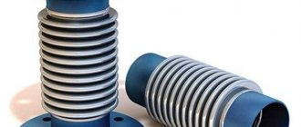
Water supply valves
In a water pipeline valve, the shut-off element is made in the form of a disk, the diameter of which is equal to the size of the internal diameter of the pipe. When the valve opens and closes, the disk rotates around an axis perpendicular to the direction of flow.
The valve body has a shortened cylindrical shape, can be dismounted or monolithic (all-welded design). It is made from cast iron alloys, different types of steels, non-ferrous metals, and composite polymers. In its cavity there is a locking organ, consisting of a movable part - a flat or biconvex disk and a fixed part - the saddle. Elastic rubber rings are used as seals.