The water jacket of a heating boiler is a container operating under pressure. In order to eliminate the risk of system depressurization due to excess pressure, a safety valve is installed for the boiler. For safe operation of the boiler unit, it is important to correctly select and install the protective device.
Heating system safety valve
Why are thermal relief valves necessary in principle?
It would seem that such a valve is not really needed.
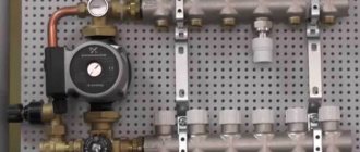
After all, other devices also provide security. In particular, a safety valve that is triggered (broken) when the pressure is exceeded. It is often called that - disruptive or disruptive. On most heating systems you can see so-called “safety groups”. They consist of a pressure gauge indicating the pressure in the circuit, an automatic air vent and a safety blow-off valve (on the left in the illustration).
We will not focus on this device now - such valves have already been reviewed on our portal earlier.
Safety valve in the heating system
Such devices usually have a very simple design and a completely understandable principle of operation. When the pressure in the system rises to a certain set point, an operation occurs with the release of excess coolant. more about the operation of the safety valve in the heating system in a separate publication on our portal.
Well, so why “fence the garden” - there is already protection, right? If something goes wrong, for example, an increase in temperature in the circuit causes an increase in excess pressure, the valve will operate and the emergency will be prevented. Is it true?
Alas, this is not always 100% true. From excess pressure, yes, such protection should help. But with temperature, the question is more complicated.
Allowing the coolant to reach the boiling point (conventionally 100 ℃) in household boiler equipment is unacceptable! Therefore, the border of 95, maximum 100 ℃ should become “impassable”. Too high a temperature can lead to deformation of the boiler heat exchanger, rupture of the pipes of the laid circuit or connections between them. to massive vapor formation and the appearance of gas locks, to other not only unpleasant, but also extremely dangerous consequences.
Do not forget that in closed volumes, with increased pressure in the system, the boiling point shifts significantly higher. That is, if the temperature is uncontrolled, an extremely dangerous situation can arise. The water has already been superheated above the limit of 100 ℃, but there is still no boiling. However, as soon as the pressure drops (a leak has appeared or a relief tap or valve has opened somewhere), the entire superheated mass of water boils at once. Explosions happen such that they simply blow down walls.
These are the consequences of a boiler explosion!
For some reason, popular rumor attributes “increased explosiveness” to gas boilers. Apparently, due to occasional reports of explosions due to gas leaks. Meanwhile, this is not so. Indeed, gas leaks are dangerous in themselves. But the greatest danger is posed by solid fuel boilers, no matter how strange it may seem.
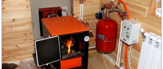
Meanwhile, this is explained quite simply. The combustion temperature of solid fuel is much higher than that of gas, and so is the energy potential. But monitoring and managing the combustion process is no example more difficult. “Tightening the wick” on gas or liquid fuel equipment is a matter of a few seconds. We are not talking about electric ones - the control there is even simpler and more sensitive. But the operation of a boiler using wood or coal is always characterized by significant thermal inertia, that is, even changes made to the fuel combustion mode do not work immediately. It is not for nothing that many solid fuel boilers are equipped with special cooling circuits - this is a necessary measure in order to prevent overheating above critical temperatures.
Yes, the pressure safety valve should take over the protection duty here. But, firstly, the operating accuracy of such spring devices is low; ±30% of the nominal value is considered the norm. For some systems, such “punctuality” is not enough. And secondly, and this is the main thing, if the heating system is equipped with an open type expansion tank, then the pressure valve becomes completely useless. It will not in any way protect the system from possible overheating and reaching the boiling point.
In open-type heating systems, the pressure safety valve becomes a useless “decoration”.
Therefore, a protection system is needed that would trigger when the upper temperature threshold is reached.
Such a “line of defense” is also necessary in other circumstances. For example, a solid fuel boiler operates in a system with forced circulation of coolant. If, due to power supply problems, the pump suddenly stops and circulation stops, an extremely dangerous situation can arise. This means that the “temperature” protection system must be completely energy-independent, capable of helping out in any case.
These types of devices include thermal relief valves.
Expert advice
- A blasting device with standard technical characteristics allows water to pass through even at low pressure levels when clogged. The problem can be solved by cleaning the body parts. To do this, the product must be dismantled and placed in a container with vinegar for 2 - 3 hours. Then rinse it with water until completely clean and install it in its original place, lubricating the connection area with alcohol.
- If the valve continues to leak even after cleaning, then most likely the rubber gasket resting on the seat is clogged with debris. It is easier to replace such a part than to clean it without deformation. Replacing the valve on the supply pipeline to the boiler can be seen in the video:
- A number of consumers quite reasonably doubt the durability of shut-off valves with plastic parts. They actually have a shorter service life, so it’s better to immediately buy ones with metal components. Such products are on average 100 - 150 rubles more expensive, but they last much longer.
- You cannot simply turn off the device, even if it is leaking. A huge number of heating boilers have failed precisely after installing the plug.
Purpose and installation location
Closed heating systems operate under a certain pressure. A significant increase in operating pressure leads to equipment failure. Connections may leak, plastic parts and elements may burst. In the most unfavorable situations, the boiler heat exchanger may explode. This is already very dangerous and threatens not only the floor flooded with hot coolant, but also burns. After all, the temperature is serious.
The overpressure relief valve must protect the heating system from excessively high pressure. As long as the system parameters are within normal limits, it does not manifest itself in any way. Although the pressure in the system gradually increases from the moment the boiler starts, the expansion tank compensates for it, maintaining a stable state of the system. But it may not do this indefinitely, although, with proper calculation, it is enough for standard situations. If the expander fails to cope with the task, the pressure begins to rise. When it exceeds the threshold, the excess pressure relief valve is activated. It simply releases part of the coolant, thereby stabilizing the emergency situation.
That is, the excess pressure relief valve in the heating system works in emergency situations. That is why it is also called “emergency”. And also “discharge”, “drain”, “protective” and “explosive”. All these are names of the same device.
What does a safety (emergency) valve for heating look like?
As is clear from the description, when the pressure increases above a certain limit, a certain amount of coolant is simply released from the system. If you came to the boiler room and a puddle formed under the emergency valve, it means there was an emergency situation during which the pressure increased. There is no other alarm. So these traces are worth paying attention to. It is worth immediately checking the functionality of the valve itself and the membrane tank. Most likely, they are the reason. If you do not pay attention to these symptoms, after a while you may encounter problems: either something will “fly” in the system, or the water heating boiler will rupture.
We recommend: Drip furnace: do-it-yourself testing, drawings, options
Installation location of the emergency heating valve - on the supply pipeline, near the boiler
Of all the equipment in an individual heating system, the most dangerous is the boiler. Therefore, the excess pressure relief valve is installed either directly on the boiler itself (if there is an appropriate outlet for installation) or on the supply line immediately after the boiler. The distance is small - 20-30 cm from the body. If the boiler does not have this type of fittings (indicated in the description), then it is installed in the so-called safety group or placed separately. The safety group is placed at the outlet from the supply line immediately after the boiler (before the first branch and any other device), on which a pressure gauge, automatic air vent and excess pressure relief valve are installed.
Types of security groups and the principle of choosing the appropriate model
A standard safety valve for a boiler may differ in design in several design features. These nuances do not change the functionality of the device, but only simplify use and maintenance. To choose the right safety unit, you need to know what safety valves for boilers are and how they differ.
Lever models
The most common type of standard safety assembly is the lever model. This mechanism can be activated manually, which is convenient when checking or draining water from the boiler tank. They do it like this:
- A horizontally located lever is installed vertically;
- direct connection to the stem activates the spring mechanism;
- the safety valve plate forcibly opens the hole and water begins to flow from the fitting.
Even if the tank is not completely emptied, a control drain is performed monthly to check the functionality of the safety unit.
The products differ in the design of the lever and the fitting for discharging water. If possible, it is better to choose a model with a flag fixed to the body. The fastening is made with a bolt that prevents children from manually opening the lever. The product has a convenient herringbone-shaped fitting with three threads, which ensures reliable fixation of the hose.
The cheaper model does not have a flag lock. You can accidentally catch the lever with your hand and unnecessary drainage of water will begin. The fitting is short, with only one threading ring. It is inconvenient to fix the hose onto such a protrusion and can tear it off under strong pressure.
Models without lever
Safety valves without a lever are the cheapest and most inconvenient option. Such models often come complete with a water heater. Experienced plumbers simply throw them away. The units operate similarly to lever models, but there is no way to manually perform a control drain or empty the boiler tank.
Models without a lever come in two versions: with a cover at the end of the body and blind. The first option is more convenient. If clogged, the cover can be unscrewed to clean the mechanism. A blind model cannot be tested for functionality and cannot be descaled. The fluid discharge fittings for both valves are short with one threaded ring.
Safety components for large water heaters
Water heaters with a storage tank volume of 100 liters or more are equipped with improved safety valves. They work in a similar way, only they are additionally equipped with a ball valve for forced drainage, as well as a pressure gauge.
Particular attention should be paid to the fluid drainage fitting. It's threaded
Reliable fastening prevents the hose from being torn off by strong pressure and eliminates the inconvenient use of the clamp.
Original models
For lovers of aesthetics and comfort, manufacturers offer original safety components. The product is equipped with a pressure gauge, chrome plated, and given an elegant shape. The products look beautiful, but their cost is high.
Difference in body markings
High-quality products must be marked on the body. The manufacturer indicates the maximum permissible pressure, as well as the direction of water movement. The second marking is an arrow. It helps to determine which side to place the part on the boiler pipe.
On cheap Chinese models there are often no markings. You can figure out the direction of the liquid without an arrow. The check valve plate must open upward in relation to the boiler pipe so that water from the water supply flows into the tank. But it’s impossible to determine the permissible pressure without markings. If the indicator does not match, the safety unit will constantly leak or will not work at all in an emergency.
Other types of valves
When they try to save money on a safety group, they try to install a blast valve designed for the heating system on the water heater. The nodes are similar in functionality, but there is one nuance. The blast valve is not capable of releasing liquid little by little. The mechanism will work when the excess pressure reaches a critical point. The blast valve can only release all the water from the tank in the event of an accident.
Separately, it is worth considering installing only a check valve. The mechanism of this unit, on the contrary, locks the water inside the tank, preventing it from draining into the pipeline. If there is excess pressure, the working plate with the rod is not able to work in the opposite direction, which will lead to rupture of the tank.
Excess pressure relief valve: types, device, principle of operation
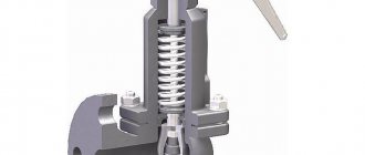
There are two types of “demolition” - lever-load and spring. Lever-load units are not used in heating private houses, so it makes no sense to consider them. Let's talk about spring "resetters". We see their structure in section in the figure below.
Spring safety valve device for heating system
A shut-off and control element or a valve itself is inserted into the metal body, which takes on the pressure of the coolant. It is pressed by a spring, the elastic force of which is designed for a certain load. When the pressure in the heating system acts on the valve with a force greater than the force of the spring, it begins to compress and the disk rises. A certain amount of coolant is drained into the opened gap, the pressure drops, and the spring blocks the flow. This is how the overpressure relief valve works.
Types and designs
Relief valves are divided into two main groups:
- direct action, opening only under the influence of pressure from the internal environment. These include devices used to prevent excessive pressure build-up in oil and fuel systems;
- indirect acting, using an external pressure source. They are more suitable for liquid and air systems.
Depending on the design features and principle of operation, they are divided into four types.
With remote sensor
The device is equipped with a spring mechanism and a rod driven by main or backup bellows. When the water overheats, they are affected by a heat-sensitive liquid rising through the capillary tube from the sensor flask.
When the device is triggered, the rod opens the plate for the movement of coolant. There are two pipes in the valve body to the supply line and to the sewerage system to discharge excess water.
Combined with make-up systems
They are a type of safety valve in heating systems that can perform 3 functions at once:
- dump overheated coolant from the boiler tank based on a signal from an external sensor;
- effectively cool the heat generator;
- automatically recharge the heating system with cold water.
The rod of such a product is equipped with two plates that can simultaneously open 2 passages: one for discharging boiling coolant, the other for supplying cold water.
The models presented in the next photo have a triple output. They are built into the pipeline in front of the heating device or boiler. The lower pipe is used to discharge the medium; two upper pipes are used to connect the water supply and make-up lines.
Spring
In such devices, the spool is driven by the compression force of the working spring. The settings of the same valve can be adjusted by replacing different types of springs included in its kit.
A number of models have an additional lever built into the body that performs manual detonation. With its help, you can manually purge the valve to check its general technical condition or release part of the working fluid.
Since the spring in most cases is exposed to the internal working environment, for devices that work with aggressive substances, it is covered with a protective layer of polymer. Such product models have stem seals like a stuffing box or bellows device.
Lever-load
The main unit of this type of valve mechanism is a lever with a weight suspended on it. The operation of the device is affected by the weight of the load and the length of the lever arm to the place where it is placed. The more massive it is and the farther it is from the rod, the higher the pressure the relief valve is triggered.
To ensure complete sealing of large seats, it will be necessary to use a heavier load, and this can lead to quite a high level of vibration of the entire device. In such cases, valves are used in which the medium discharge cross-section is formed by two parallel seats. The body of such a device also contains two shutters that operate in parallel. This design reduces the weight of the weighting material and the length of the levers and has a positive effect on increasing the rate of operation of the unit.
Advantages and disadvantages
The relief valve has the following advantages:
- eliminates water hammer and pressure surges;
- prevent the appearance of air pockets in the liquid media transportation system;
- simple design that is easy to maintain and repair;
- relatively low cost;
- possibility of automatic control and pressure release;
- simple installation technology;
- unpretentiousness to operating conditions;
- do not require frequent maintenance.
Flaws:
- presence of operating error;
- increased wear of critical parts;
- limited service life.
Simple valve design
Controls and technical characteristics
The simplest models of low-flow blast valves, used mainly for domestic engineering systems, are manually controlled mechanically. Products installed on large-section production pipelines can be controlled remotely.
Depending on the material of manufacture and design features, the devices are endowed with different technical characteristics.
The characteristics of several models of emergency pressure relief valves designed to work with gaseous substances are presented in the table.
Determination of the conditional cross section and response threshold
It is easy to determine the cross-section of the emergency valve - it must be no less than the diameter of the supply pipe. Otherwise, it will not work as it should. When installing not as part of a safety group, we make the tap with a slight slope towards the boiler (it can be vertical, but definitely not in the opposite direction). If your wiring is inch, we use the same pipe to make an outlet, and install a blast valve of the same cross-section. This is understandable.
Can be part of a security group or installed separately
The response threshold is determined based on the operating pressure of the system. For normal operation it should be 20-30% higher. If your heating operates at 1.2 Bar, then the excess pressure relief valve should operate at 1.45-1.55 Bar.
It is not always possible to find an emergency valve with the required response value. You can either take one with similar parameters, or find an adjustable one (there is one for 1.5 Bar).
Installation rules, replacement frequency
An emergency valve is always installed on the supply side, after the boiler. In this case, the following rules are observed:
- If the relief valve is installed separately, a pressure gauge is placed in front of it to monitor the condition of the system.
- Placed at a distance of 20-30 cm from the boiler.
- The outlet is made with a pipe of the same diameter as the supply pipeline. To determine the pressure as accurately as possible, it may have a slight slope towards the boiler.
- Shut-off devices (taps, check valves, etc.) must not be installed between the boiler and the blast valve.
- In systems with natural circulation, this device is placed at the highest point of the system.
Placed close to the boiler (in many models it is located in the boiler itself, in some boilers there is space for installation)
To prevent the discharged coolant from leaking onto the floor, you can put a hose on the outlet pipe. It can be placed in a container or discharged into the sewer. But in this case, it is necessary to somehow monitor the operation - set an alarm. After all, he doesn’t just play off, but for some reason.
Another important point: after several operations (5-6), the excess pressure relief valve must be replaced. This is due to spring wear. The device starts to work incorrectly. The valve costs a little, so it’s not expensive. The only unpleasant point is that locking devices cannot be placed in front of it. Therefore, the emergency valve can only be removed by completely stopping the system and reducing the pressure to atmospheric pressure. That's the rub.
Where to install the overpressure relief valve
The situation can be improved if shut-off valves are placed after the demolition man. In this case, at least you won’t have to drain the coolant from the system, but only from the boiler, which is not so scary.
Types of overpressure relief valves
There are several generally accepted classifications of safety valves. Depending on the method of action, there are:
- direct-acting valves - devices are activated by direct action of the working medium on the spring mechanism;
- indirect action - operate under the influence of an external pressure source (hydraulic fluid or electric drive).
Based on the type of load on the membrane, the device is divided into the following types:
- cargo - the most common mechanism for adjusting the working pressure in the system;
- spring - the pressure of the working medium is counteracted by a lever that presses on the rod, holding it in the closed position;
- lever-spring – hybrid devices equipped with a spring and a lever mechanism;
- magnetic spring valves are indirectly acting valves equipped with an electromagnetic drive.
Modern manufacturers offer other types of excess pressure relief valves.
For example, there are thermal relief valves on the market that respond not to an increase in pressure, but to an increase in the temperature of the working environment. They may have a remote or built-in temperature sensor, which operates on the basis of a heat-sensitive liquid located in a bellows.
When the water temperature heats up to 95-100 degrees, the liquid in the capillary tube of the sensor flask puts pressure on the bellows, which opens the rod and drains the superheated water to normalize the pressure.
We recommend that you read: Shut-off valves and their use in pipeline systems
According to the control method, the valves are divided into two groups: manual and automatic - they are controlled, respectively, manually or are activated automatically when the pressure of the working medium increases. In addition, there are regulated and unregulated. Adjustment allows you to set any water pressure threshold.
Depending on the type of working medium, there are water and air. The former remove excess liquid, the latter discharge excess gases from the system, preventing airing of circuits in closed heating systems.
There are also control valves equipped with a built-in thermostat, which changes the throughput of the device, slightly opening or completely blocking the outflow of the working medium. Such devices are usually installed at the entrance to the heating radiator in the room.
Recommendations for choosing an air valve
Theoretically, an automatic air release valve can be installed in all necessary places. But in practice, the scope of application of automatic machines is limited for many reasons. For example, the design of the Mayevsky crane is simpler and has no moving parts, so it is more reliable. The manual tap is a cylindrical body made of plumbing brass with external threads. There is a through hole made inside the housing, the passage in which is blocked by a screw with a conical end.
A round calibrated channel extends from the main hole located in the center. When you unscrew the screw between these two channels, a message appears, causing air to leave the system. During operation, the screw is completely tightened, and to release gases from the system, it is enough to unscrew it a couple of turns with a screwdriver or even by hand.
In turn, an automatic air valve is a hollow cylinder, inside of which there is a plastic float. The operating position of the device is vertical, the internal chamber is filled with coolant entering through the lower hole under the influence of pressure in the system. The float is mechanically attached to the needle release valve by means of a lever. Gases coming from the pipelines gradually displace water from the chamber and the float begins to descend. As soon as the liquid is completely displaced, the lever will open the valve and all the air will quickly leave the chamber. The latter will immediately be filled with coolant again.
The internal moving parts of the automatic air release gradually become covered with scale, and the working openings become silted. As a result, the mechanism jams, gases come out slowly, and water begins to flow through the assembly with the needle. This type of air release valve is easier to replace than to repair. Hence the conclusion: car air vents are installed only in those places where it is impossible to do without them. They are selected for:
- boiler safety groups where the coolant temperature is the highest;
- the highest points of vertical risers, where all gases rise;
- distribution manifold for underfloor heating, where air from all heating circuits accumulates;
- loops of U-shaped expansion joints made of polymer pipes, turned upward.
When choosing a device, you should pay attention to 2 parameters: maximum operating temperature and pressure. If we are talking about a heating scheme for a private house up to 2 floors high, then, in principle, any automatic air vent valve will do
The minimum parameters of air vents offered on the market are as follows: operating temperature up to 110 ºС, pressure range in which the device operates effectively - from 0.5 to 7 Bar.
In high-rise cottages, circulation pumps can develop higher pressure, so when selecting, you need to focus on their performance. As for the temperature, in private residential networks it rarely exceeds 95 ºС.
Advice. Experts and practitioners recommend purchasing car air vents with an exhaust pipe directed upwards. According to reviews, a device with a side exit begins to leak much more often. In addition, during installation it is necessary to strictly observe the vertical position of the housing.
Manual air vents for heating systems (Mayevsky taps) are most often accepted for installation on radiators. Moreover, many manufacturers of sectional and panel appliances complete their products with taps for gas removal. In this case, there are 3 types of air vents according to the method of unscrewing the screw:
- traditional, with slots for a screwdriver;
- with a rod in the form of a tetrahedron or other shape for a special key;
- with a handle for manual unscrewing without any tools.
Advice. The third type of product should not be purchased for a home where preschool children live. Accidentally opening the tap can lead to serious burns from the hot coolant.
Criterias of choice
The safety valve in the heating system performs an important function - it prevents the boiler from boiling over and reduces the pressure that has risen to the limit values.
It is recommended to choose a spring device, but it is important to pay attention to the following points
:
- range of values at which the valve is able to operate (selected in accordance with the parameters of the heating system);
- type of valve - open or closed (in the first case, the coolant is discharged into the atmosphere, in the second - into the return pipeline);
- plate lifting height (selected based on throughput).
The selection of a pressure relief device is based on the technical characteristics of the heating system - the thermal power of the boiler unit and the maximum pressure of the medium in the pipeline.
Mechanism
The emergency relief valve must operate in a timely manner, which depends on the characteristics of its mechanism, the key elements of which are the rod, spring and disc.
Safety valve device
The main characteristic of the valve is the percentage difference between the pressure in the pipeline at the moment the rod begins to move and the pressure when the passage is fully open to discharge excess coolant. This parameter also depends on the nominal pressure in the heating system. The response speed of the device depends on the operating pressure in the system - the higher it is, the faster the valve should open.
It is important that the adjustment mechanism does not come into contact with the coolant. The coils of the spring must not touch each other. If the valve is idle for a long time, the spring may “stick” - in this case, the device will not be able to operate on time. A special rod for manually retracting the spring makes it possible to check the operation of the valve from time to time. The relief valve also provides frost protection.
Note! The valve opens completely when the pressure in the heating system increases by 10% of the set value, and closes completely when the pressure level drops by 20% relative to the response parameter. It is recommended to choose for installation a model whose response pressure exceeds the operating parameters of the heating system by 20-30%.
Pipeline supply
To prevent hydraulic resistance from affecting the operation of the safety device, the diameter of the valve must correspond to the diameter of the supply pipe or be larger.
Pipeline option
Attention! To reduce hydraulic losses when the coolant pressure is applied to the plate, the emergency valve is mounted with a slope towards the boiler unit.
Material of manufacture
Brass is usually used to make the body, since this material has low thermal expansion, corrosion resistance, durability and an affordable price.
We recommend: Operating principle of atmospheric gas boilers: advantages and disadvantages of heating equipment
The control unit is made of heat-resistant plastic, which does not change its geometry and retains the necessary rigidity even under the influence of a coolant brought to a boil.
Purpose of the gas valve
PSK is a safety valve element responsible for the safety of the gas pipeline and gas equipment connected to it. During operation, the valve is in a closed position, therefore it is classified as a closed pipe fitting.
Such devices are installed not only on gas pipelines, they are an integral part of other communications - water supply, heating networks. Everywhere they perform the same function - they stabilize the pressure in the network, provide the operating parameters necessary for the proper functioning of the system.
The valve serves to relieve excess gas if pressure parameters become critical. Fuel that creates an imbalance in the system is discharged into an auxiliary pipeline or discharged into the atmosphere
The pressure surge is usually short-lived and depends on a number of factors.
Reasons that can cause excess pressure in the system:
- breakdown of connected gas equipment - double-circuit boiler, instantaneous water heater or capacitive boiler, shut-off valves;
- use of fuel of inappropriate composition;
- change in temperature indicators in the pipeline;
- failure in the thermal-mechanical circuit.
The installation location of the gas safety valve is standard, depending on the efficiency of the application: either in the pressure regulator, or immediately behind it. After automatic operation of the valve, it returns to its operating – closed state.
In a gas network, the valve is a separate device or integrated into the pressure regulator. It is triggered if the operating gas pressure exceeds the nominal level by 15%
What are the consequences of the absence of a PSK on the network? The most common consequences are mechanical destruction of the pipeline or breakdown of connected equipment, which can cause a gas leak.
There is also a possibility of an explosion, so it is necessary to constantly monitor the serviceability of the device, carry out timely maintenance and replace failed elements
Along with relief devices, gas safety shut-off valves are also used, with the help of which the fuel supply is shut off. This happens automatically. The shut-off valve element is installed on the pipeline, in the gap between the filter and the pressure regulator.
The operating limit of the SPD is indicated in the technical data sheet of the device. The upper critical parameter is usually equal to the formula: slave. pressure +25%.
How to choose a safety valve
The main criterion for choosing a safety device is the technical parameters of the heating system specified in the design documentation.
Most modern closed heating systems use standard direct acting brass safety valves.
They are suitable for installation in systems operating on diesel, gas or electric boilers. When a critical temperature and pressure is reached, the safety valve almost instantly stops further heating of the working environment and prevents an accident.
Simple brass safety valves are designed to exceed the pressure of the working medium up to 3-6 bar.
When choosing a valve for diesel, gas and electric boilers, you need to select safety devices that can withstand pressure 20-25% higher than the normal operating pressure in the system.
For solid fuel boilers operating on peat, briquettes or coal, you need to choose the type of waste dumps more carefully, because solid fuel cannot stop burning instantly and continues to heat water for some time after switching off.
They are suitable for modern thermal relief valves with a maximum operating pressure of 10 bar. The same applies to solid fuel boilers in open heating systems, in which relief valves work most effectively by responding to an increase in operating temperature rather than pressure.
Important! When choosing a safety device, be sure to study the technical documentation for the boiler equipment. Manufacturers usually specify the required maximum pressure and temperature specifications for which relief valves are purchased.
It is not advisable to choose cheap engineering equipment from Chinese manufacturers: it is usually not of high quality and quickly breaks down. An indicator of wear is an increase in the number of valve operations.
We recommend that you read: Why do you need a check valve for water and how to install it correctly?
Clamping mechanism
Lever-load safety valves are designed for heavy loads and a pipe diameter of at least 200 mm, therefore they are used in industrial heating systems.
For individual heating of a private house, it is better to purchase a device with a spring mechanism; this is a standard, reliable and frequently used type of relief valve.
If you are on a budget, we recommend purchasing a more efficient thermal relief valve, which will prevent the problem before the pressure in the heating system seriously increases.
Lifting height
Pressure relief valves have different valve lift heights:
- Low-lift model PS-350. Low-lift . The height of the shutter in low-lift valves does not exceed 1/20 of the seat diameter. They have a relatively low throughput and a simple design. Used in lines with liquid coolant. As a rule, low-lift safety valves are sufficient for a heating system with a water circuit with a power of up to 40-43 kW. To prevent an accident in such systems, it is necessary to discharge a small volume of coolant.
- Full lift . The height of the valve in full-lift valves is greater than or equal to the diameter of the seat. As a rule, these are lever-load mechanisms, more expensive and complex in design. Full-lift valves have a high capacity and can be installed on lines in which gases, steam or compressed air circulate.
Full lift model PN 16.
Mechanism response speed
Based on response speed, safety valves are divided into proportional and on-off.
In heating systems of a private home, it is better to use proportional valves; again, they are sufficient for most systems. The shutter cover of such devices opens gradually, in proportion to the increase in pressure in the line, and accordingly, the volume of coolant discharged increases proportionally. Such valves do not self-oscillate, they maintain the correct pressure level and are cheaper.
Two-position safety valves are distinguished by instantaneous detonation and full opening of the valve. This mechanism allows you to quickly release large volumes of coolant, but creates the risk of water hammer: due to the rapid release of a large amount of coolant liquid, the pressure in the line significantly decreases, after which the valve closes sharply. Therefore, it is recommended to install two-position safety valves on lines with a compressible medium (air, gas, steam).
Diameter
The diameter of the pressure relief valve in the heating system should not be less than the connector of the supply pipe. Otherwise, the constant hydraulic pressure will interfere with the operation of the mechanism.
Manufacturer
Since safety valves have a fairly simple design, and modern models are in most cases made of brass using the same technology, there are no critical differences between valves from different manufacturers.
The difference between some is higher quality processing, inspection and testing of devices and a guarantee of a long service life without leaks - from 15 years. There are manufacturers whose safety valves we can recommend above all: VALTEC , WATTS , Protherm .
Design features and operation
Consider in detail how a safety valve with a spring works. Its body is made using hot stamping technology from brass. The main working element is a spring, which presses the membrane that covers the seat.
Valve with spring mechanism
On the rod connected to the handle there is a washer that serves as a stop for the upper end of the spring. Using the handle, the position of the washer and, accordingly, the clamping force on the membrane are changed. The spring is made of steel; the handle, seals and membrane are made of polymer materials.
The operating principle of the device is as follows: as long as the parameters of the coolant do not exceed the specified maximum permissible values, the membrane tightly closes the hole. When the situation is close to an emergency, as the pressure increases, the superheated coolant (a mixture of water and steam) lifts the membrane, overcoming the resistance of the spring. Thanks to this, the steam-water mixture is discharged out through a special hole. After dumping the excess volume of the steam-water mixture, the pressure in the pipeline decreases, and the coolant again loses the ability to compress the spring.
Note! The device can operate cyclically if the boiler is operated at maximum power, heating the coolant to 90-95 degrees. This mode of operation has a negative impact on the protective device - after several operations the blast valve begins to leak due to loss of tightness.
Installation and configuration rules
When planning to independently install a safety valve for heating, you should prepare a set of tools in advance. The work cannot be done without adjustable wrenches and wrenches, a Phillips screwdriver, pliers, a tape measure, and silicone sealant.
Before you begin, you need to determine a suitable location for installation. It is recommended to install the safety valve on the supply pipeline near the boiler outlet pipe. The optimal distance between elements is 200-300 mm.
All compact household fuses are threaded. To achieve complete tightness when screwing, it is necessary to seal the pipe with tow or silicone. It is not advisable to use FUM tape, since it does not always withstand critically high temperatures.
In the regulatory documentation that comes with each device, the installation process is usually described step by step.
Some key installation rules are the same for all types of valves:
- if the fuse is not mounted as part of a safety group, a pressure gauge is placed next to it;
- in spring valves, the spring axis must have a strictly vertical position and be located under the device body;
- in lever-load equipment, the lever is placed horizontally;
- On the section of the pipeline between the heating equipment and the fuse, the installation of check valves, taps, gate valves, and a circulation pump is not allowed;
- to prevent damage to the body when rotating the valve, you need to select the wrench from the side where the screwing is carried out;
- the drain pipe, which discharges the coolant into the sewer network or return pipe, is connected to the outlet pipe of the valve;
- the outlet pipe is not connected to the sewer directly, but with the inclusion of a funnel or pit;
- in systems where fluid circulation occurs according to a natural pattern, the safety valve is placed at the highest point.
The nominal diameter of the device is selected on the basis of methods developed and approved by Gostekhnadzor. In resolving this issue, it is wiser to seek help from professionals.
If this is not possible, you can try using specialized online calculation programs.
To reduce hydraulic losses during medium pressure on the valve plate, installation of emergency equipment is carried out with a slope towards the boiler installation
The valve adjustment is affected by the type of clamping structure. Spring devices have a cap. The pre-compression of the spring is adjusted by rotating it. The adjustment accuracy of these products is high: +/- 0.2 atm.
In lever devices, adjustments are made by increasing the mass or moving the load.
After 7-8 operations in the installed emergency device, the spring and plate wear out, as a result of which the tightness may be broken. In this case, it is advisable to replace the valve with a new one.
Required tools and materials
To install the valve you will need:
- adjustable wrench;
- fum - ribbon or tow;
- special paste for sealing joints.
Connection diagram
For example, let's look at the installation diagram of the device in front of the hot water heater in the apartment.
Work progress
Each product designed for releasing excess pressure is equipped with installation instructions, which should be carefully studied before starting work. Before installation, you also need to disconnect the water heater from the network and drain the water from it. The valve must be placed on the cold water supply up to the shut-off valve. The valve installation sequence is as follows:
- marking the installation site;
- removing a part of the pipe of a size corresponding to the length of the device body;
- threading the ends of pipes:
- covering the threaded part with tow or fum tape;
- screwing the valve onto the pipe thread;
- connecting to another pipe a pipe leading to the sewer system.
- tightening the threaded connection using an adjustable wrench;
- sealing the joint with a special paste;
- setting up the device in accordance with the passport values (if necessary).
Connection type
Based on the type of connection or connection to the pipeline, valves are divided into:
- flanged products - equipped with flange plates at each outlet and connected to mating flanges at the ends of the pipes using bolts;
- threaded - imply the presence of outlet pipes with external threads;
- welded - attached to the gas pipeline by welding and ensure 100% tightness.
Adjusting the mechanism for proper operation
The safety valve is adjusted after completion of installation work and complete flushing of the system. Spring devices can be adjusted by rotating the adjusting knob (colored plastic cap), the rotation compresses or decompresses the spring that puts pressure on the spool. In lever-load trucks, this is done by hanging a load on the lever.
It is necessary to set the set pressure, full opening and closing:
- The setting pressure should be set slightly higher than the maximum operating pressure of the boiler.
- The full opening pressure should not exceed the maximum permissible standards of the most vulnerable element of the system, usually the boiler heat exchanger, designed for 3 or 2 bar, and in some Russian models even 1.5 bar.
- The valve closing pressure must be set slightly higher than the minimum allowable for system operation.
Combined operation of valve and expansion tank
The expansion tank in the heating system is designed to stabilize the pressure. But the mistake is the opinion that with such a tank a safety valve will not be needed. The tank may not work correctly and may simply be out of air.
It is also a mistake to believe that the valve can take on the functions of an expansion tank - releasing pressure as soon as it has increased slightly. This device is not structurally designed for multiple operations and after several resets, a constant leak appears through it...
The safety valve is designed only to operate in the event of an emergency increase in pressure above the norm, after which the personnel must take measures to eliminate the causes of this situation.
In what cases does the valve usually trip?
There are four typical situations when a heating valve is triggered.
- Fluid is pumped into the system using a hand pump without pressure control, or automatic filling turns out to be defective and produces increased pressure.
- The heating system is faulty - the expansion tank was not installed or was turned off by the tap.
- The expansion tank is not working properly - there is no air in it.
- Boiler boiling with massive release of steam.
In which systems is pressure protection installed?
- The heating system of a private house is equipped with a safety valve. Even if automated boilers have rapid shutdown protection when the temperature rises, it is recommended to equip the system with an independent emergency pressure valve.
- It is also installed in the hot water supply (DHW) system, with the exception of the case when the water is heated by a flow method....
- Emergency pressure relief is installed in individual closed circuits of the system, heated by a heat exchanger or other energy source.
- In various hydraulic (air) systems operating under pressure or with a compressor….
What it is?
A dry technical definition says: an overpressure valve is a fitting that automatically releases excess water when excess pressure occurs.
It is a direct-acting device because it reacts directly to the influence of a heated medium (water or other coolant).
As a rule, an overpressure valve is included in the basic package of all compact water heating devices.
Sometimes an overpressure valve is confused with a check valve. Often both devices are placed in a single housing, which is why confusion arises. However, these devices are used to perform different tasks and are fundamentally different from each other .
What response pressure, which valve to choose
The standard set response pressure of the safety valve for a home heating system is 3 atm. The usual preliminary air pressure in the expansion tank is 1.5 atm. The operating pressure in the system after heating to maximum temperatures is 2.0 – 2.5 atm.
Accordingly, when this value increases, the situation becomes “emergency”. When 3.0 atm is reached, or slightly lower, the valve should begin to operate. Let us recall that the lowest strength limit of individual heating equipment, low-quality expansion tanks, for example, is only about 4.0 atm, and it is often exceeded when manually pumping coolant...
You should only choose a safety valve for your heating system from a reputable manufacturer. This device is simple, but it must be made accurately, and not all residents will like the explosion of the boiler...
Simple ways to extend the life of the device
No water heater owner wants to be left without hot water, for example, when he comes home from work. And such breakdowns, according to the law of meanness, happen at the most inopportune moment. But by applying some knowledge in practice, you can minimize the likelihood of a malfunction.
- The tank of a household water heater critically perceives increased pressure in the system, and the cause of a crack may be exceeding three atmospheres. To prevent this, you should install a special adjustable gearbox with a pressure gauge. By setting the nominal pressure at 2 atmospheres, you can significantly extend the service life of the device body.
Household gearbox with pressure gauge
- The main pest of the internal surfaces of a water heater is scale. It is impossible to completely get rid of it, since the quality of water from the centralized water supply leaves much to be desired. Therefore, at least once every six months it is necessary to clean the device, not forgetting the heating element.
- At the same time as cleaning the tank, you should check the condition of the magnesium rod. This element is the main degree of protection against corrosion. When its length is reduced to the minimum mark, the magnesium rod must be replaced with a new one.
- Do not set the heating temperature of the liquid above 50 degrees. Elevated temperatures negatively affect the condition of the body, as well as welds.
- To reduce the impact of scale on the device body and heating element, you can install a filter on the liquid supply tube. It is not necessary to choose an expensive model; you just need to replace it on time.
Water heater filter
The methods described above do not require any effort or expenditure of large funds, but will help protect the water heater from many breakdowns and malfunctions.
Why might a valve leak?
The pressure relief valve in the heating system can leak for various reasons. In some situations, this is an acceptable natural process; in other cases, a leak indicates a malfunction of the device.
Leakage of the protection valve can be caused by the following reasons:
- Damage to the sealed rubber cup or disc as a result of repeated use. If during repairs a replacement part cannot be found on sale or is not included in the package, you will have to replace the device completely.
- In spring types, the opening of the side drain pipe occurs gradually; at borderline pressure values or short-term surges, the valve may partially operate and drip, which does not indicate its malfunction.
- Leakage can be caused by incorrect settings or malfunctions of the expansion tank - damage to its membrane, air escaping through a depressurized housing or a damaged nipple. In this case, sharp pressure surges are possible as a result of water hammer, causing periodic short-term leakage of coolant through the safety valve.
- The cause of leakage in some adjustable valves is fluid seeping down the stem through the top during actuation.
- If a back pressure is created at the outlet pipe above the device's response threshold, a leak will also occur.
The safety valve of steam boilers is designed to protect them from excess pressure in the system caused by various factors, and is a mandatory element when operating this type of equipment. There is a wide range of safety devices on sale from Chinese, domestic and European manufacturers, which are characterized by a relatively low cost. When purchasing, it is rational to choose a protective group from several devices, which additionally includes a pressure gauge and an air release valve.
