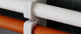
All apartment owners are prohibited from connecting water heated floors directly from a heated towel rail. Firstly, these actions relate to illegal redevelopment, and secondly, an unaccounted amount of thermal energy is consumed, for which all residents of the entrance/house pay.
However, there is a legal way to use a water heat exchanger in an apartment - installing a heat exchanger. According to existing standards SP, SNiP, water heated floors can be installed only in bathrooms of a combined type, toilets and bathrooms; wiring above living rooms is prohibited on all floors of an apartment building, except for the first lower level.
What is a water heated floor
Water heated floor is a low-temperature heating system, where the coolant is supplied at a temperature of 35-45°C, according to standards not higher than 55°C. In addition, a warm floor is a separate circulation circuit, which requires a separate circulation pump.
Heated floors have restrictions on the temperature of the floor surface - 26-31 ° C. The maximum temperature difference between the supply and return lines of a heated water floor is allowed to be no more than 10°C. The maximum coolant flow rate is 0.6 m/s.
Main advantages
Compared to the old technology with radiator batteries, the new technique has a number of advantages:
- A heated layer at the level of the feet of human feet. Feet are warm, head is moderately cool - this stimulates the human body to active life.
- The labor-intensive procedure of removing dust from hard-to-reach areas of radiators is eliminated.
- Uneven heating stimulated colds. In the case of heated floors, all these disadvantages are absent, the surface is easy to sweep and wash;
- Space is freed up, there is no need to think through options for how to fit radiator batteries and pipes into the interior of the room;
- Installation work has become much easier;
- Carrying out the work and the main elements of the system are cheaper. To heat the room, a temperature in the pipes of 55 ̊C and no more than 60-70 ̊C is sufficient. Installation and further operation of heated floors turns out to be 30% cheaper. Therefore, many people wanted to know how to make a water-heated floor.
Scheme 1. Connecting a heated floor directly from the boiler
This connection diagram for a water heated floor has a heat generator, safety fittings with a pump. The coolant directly from the boiler enters the distribution manifold of the heated floor and then diverges through the loops and is reversed back to the boiler. The boiler must be set to the temperature of the warm floor.
This raises two nuances:
- It is advisable to use a condensing boiler for installation, because Low temperature mode is optimal for it. In this mode, the condensing boiler has maximum efficiency. In a conventional boiler, when operating at low temperatures, the heat exchanger will very quickly fail. If the boiler is solid fuel, then a buffer tank is needed to correct the temperature, since this boiler is difficult to adjust temperature.
- A good option for underfloor heating is when it is connected to a heat pump.
How to install a pump in a heated floor system
The quality of the warm water floor largely depends on the correct installation of the pump. Any installation scheme for a circulation pump requires that the pump shaft be placed strictly parallel to the floor surface. If you place the shaft vertically, the pump model you are using will lose at least 30% of its performance. When deciding how to properly connect a pump for a heated floor, you must be guided by the following recommendations. The pump is installed in the system as follows.
A bypass is installed at the selected installation location (this is what the bypass pipe is called):
- the main pipe is cut;
- threads are cut at its ends (for metal pipes);
- a ball valve is installed, which is connected to the pipe with a coupling and lock nut;
- in cases where the pipes are plastic, the ball valve is soldered into the main line (one-piece connection) or installed using an “American” connection.
If the pump fails for any reason, the movement of coolant through it is blocked by ball valves installed at the inlet and outlet of the pump. And the valve on the main pipe opens. And the coolant moves in natural circulation mode.
The installation diagram of the circulation pump involves installing a coarse filter in front of the pump itself. Its presence increases the service life of the pump and reduces the likelihood of its failure.
The circulation pump is connected to the boiler in such a way that it is on the “return”, in close proximity to the heating boiler. In this case, the pump pushes the coolant in the direction of the boiler and operates at minimal thermal loads. And this has a positive effect on increasing service life.
The second argument for installing the pump in this particular location is the specific operation of most models of thermal boilers. Air often collects in their upper parts (especially in floor-standing models). A pump installed on direct supply, drawing coolant from the boiler, can create a vacuum in its upper part. As a result, the boiler boils. If the pump supplies water to the boiler, then there is practically no air cushion in the upper part of the boiler and the threat of boiling is reduced to zero.
Scheme 2. Installation of heated floors from a three-way valve
three way thermostatic valve diagram
In most cases, with such a scheme for installing and connecting a water heated floor, we have a combined heating system, there are heating radiators with a temperature of 70-80°C and a heated floor circuit with a temperature of 40°C. The question arises of how to make forty out of these eighty.
For this, a three-way thermostatic valve is used. The valve is installed on the supply side, after which a circulation pump must be installed. From the return of the heated floor, the cooled coolant is mixed with the coolant that is obtained from the boiler circuit and which is subsequently reduced to operating temperature using a three-way valve.
The disadvantage of this scheme for laying out a heated floor is that it is impossible to control the proportionality of mixing the cooled coolant with the hot one, and underheated or overheated coolant can flow into the heated floor. This reduces the comfort and efficiency of the system.
The advantage of this scheme is ease of installation and low cost of equipment.
This scheme is more suitable for heating small areas and where there are no high customer requirements for comfort and efficiency, where there is a desire to save money.
In real life, the circuit is extremely rare due to the instability of radiators connected to a single pipe. When the three-way valve is opened slightly, the heating circuit is energized, and the pump pressure is transferred to the main line.
Example implementation:
Connection via three-way valve
A slightly different assembly and operating principle is the option of connecting a heated floor through a three-way valve, which is shown with an arrow in the diagram below.
- This scheme is used in cases where, in addition to a heated floor, the system also contains a main heating circuit. The temperatures of the coolant in them will be different, which is why a mixing valve is needed.
Connection via three-way valve
- This device not only regulates the water supply to the circuit (it is mounted on the supply pipe in front of the circulation pump), but also at the same time, using a built-in thermostat, controls its temperature, mixing cold coolant with hot one. In this case, the pressure in the pipeline corresponds to the pressure set on the pump.
- However, the valve cannot accurately dose the amount of water for mixing, so the temperature in the floor circuit may be either underheated or too hot. The problem is solved by connecting a servo drive to it, since it is this that balances the operation of the system and protects the floors from overheating.
Three-way mixing valve
On a note! If the area of the heated floor is small, you can introduce not a three-way valve, but a two-way valve into the system. It has a lower throughput, and the principle of mixing the coolant in it is somewhat different. But in general, the option is quite reliable and is perfect for a small circuit.
The circuit with a mixing valve is quite accessible for self-installation, and the equipment for it does not require large expenses.
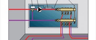
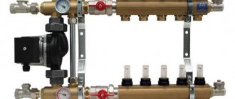
Diagram 3. Distribution of heated floors from the pumping and mixing unit
mixing module
This is a mixed scheme for connecting a water heated floor, where there is a radiator heating zone, a heated floor and a pumping and mixing unit is used. The cooled coolant is mixed from the heated floor return to the boiler.
All mixing units have a balancing valve, with which you can dose the amount of cooled coolant when mixing it with the hot one. This allows you to achieve a clearly defined temperature of the coolant at the outlet of the unit, i.e. at the entrance to the heated floor loops. This significantly increases consumer comfort and efficiency of the system as a whole.
Depending on the model of the unit, it may include other useful elements: a bypass with a bypass valve, a balancing valve of the primary boiler circuit, or ball valves on both sides of the circulation pump.
Hydraulic separator
This circuit is used in combined heating circuits with radiators. In essence, it is a diagram of the hydraulic separation of a radiator heating system and a warm floor system.
If a circulation pump is used in a radiator heating system, then the presence of a second pump in the mixing unit can lead to a conflicting violation of the hydraulic modes.
To operate two pumps in parallel, a hydraulic separator or heat exchanger is installed in the heating system. Example on the diagram.
Diagram 4. Connecting a heated floor from a radiator
These are special kits designed to connect one underfloor heating loop to an area of 15-20 sq.m. They look like a plastic box, inside of which, depending on the manufacturer and configuration, there may be coolant temperature limiters, room air temperature limiters and an air vent.
The coolant enters the loop of the connected water heated floor directly from the high-temperature circuit, i.e. with a temperature of 70-80°C, cools down in the loop to a given value and a new batch of hot coolant enters. An additional pump is not required here; the boiler must cope.
The disadvantage is low comfort. Overheated zones will be present.
The advantage of this scheme for connecting a water heated floor is that it is easy to install. Such kits are used when there is a small area of heated floors, a small room with infrequent occupants. Not recommended for installation in bedrooms. Suitable for heating bathrooms, corridors, loggias, etc.
Let's summarize and put it in a table:
| Connection type | Comfort | Efficiency | Installation and configuration | Reliability | Price |
| Regular gas, TT or diesel | ± | ± | + | ± | + |
| Condensing boiler or heat pump | + | + | + | ± | — |
| Three way thermostatic valve | ± | ± | + | + | ± |
| Pumping and mixing unit | + | + | ± | + | — |
| Thermal mounting kit | — | ± | + | + | + |
Master plumbers and heat and gas supply experts recommend avoiding schemes for connecting water heated floors to working heating branches. It is better to power the heating circuits of the underfloor heating directly to the boiler so that the floor heating can function independently of the radiators, especially in the summer.
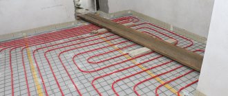
Laying schemes for water heated floors
Methods for laying out floor heating pipes
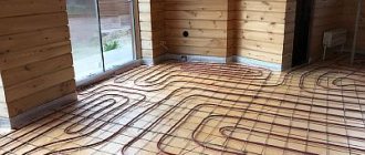
There are three main ways of laying a water-heated floor: snake, spiral (snail) and a combination of these options. Most often, heated floors are installed with a snail; in some places a snake is used.
Installation diagram "Snail"
Laying a warm snail allows you to distribute heat more evenly throughout the room. With this layout, the pipe is mounted in a circle towards the center, then from a circle in the opposite direction.
When laying out a heated floor with a snail, you need to provide an indent for laying out the pipe in the opposite direction.
Laying heated floors with a snake
With this installation, the underfloor heating pipe is mounted in one direction and, when the circuit is laid out, it simply returns to the collector return. With this device, at the beginning of the circuit the coolant temperature is hotter, at the end it is colder. Therefore, the snake layout is used quite rarely.
Calculation of heated floors
Before connecting the heated floor according to the developed scheme, it is necessary to make a preliminary calculation. You can do a rough calculation yourself using the following steps:
- Determine the location of the collector. Most often it is mounted in the center of the floor.
- Try to schematically depict the layout of underfloor heating pipes, observing the following information: with a step of 15 cm per square meter of pipe, 6.5 meters of pipe are spent, the length of the pipe should not exceed 100 meters, the contours should all be approximately the same.
- We decide on the footage of all circuits and in general we can begin installation.
Also, do not forget to do thermal calculations of the building. There are many ready-made calculators on the Internet. If the heat loss in the room does not exceed 100 W per square meter, then your heated floor will not require additional heating devices.
Selection by characteristics
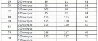
Let's look at the graphs of the characteristics of Grundfos circulation pumps called Solar.
We see that the “youngest” pump 25/40 is capable of delivering a flow rate of 1.7 m3/hour at a pressure of 2 meters. He will do this at the second speed, consuming 50 W per hour.
We choose 25/40 for heated floors up to 100 sq. m. (7 circuits of 12 - 13 sq. m.) Over 120 sq. m. – respectively 25/50 up to an area of 160 sq. m.
Based on rough estimates, we have chosen a suitable pump for the heated floor. What will the manufacturer say? Here is the official recommendation table from Grundfos.
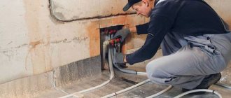
Installation of heated floors
Once you have decided on the layout and connection of the water floor, you need to start installation.
- Prepare the base of the heated floor. It should be level with a minimum difference in height.
- Install waterproofing if required by local codes
- Lay polystyrene 10 cm thick on the first floor and 5 cm on the subsequent ones.
- Lay polyethylene so that less screed comes into contact with the insulation.
- If your method of fastening is a reinforcing mesh, then lay it on polyethylene
- Lay out the heated floor pipe according to the approved diagram
- Pressure test the system
- Fill the screed