The variety of choices and wide range of pipeline fittings available on the modern market allows you to make the right choice among different types of valves, depending on the scope and characteristics of the application. A special gate valve, presented on our website in a broad classification, is an important and widely demanded mechanism for regulating the flow of contents of various pipelines, without which large industrial enterprises of a public and private nature, as well as smaller public utility organizations, cannot do.
The gate valve gets its name from the German term “schieber” (gate), derived from the verb “schieben”. The literal translation into Russian of this concept means to push, move or thrust. Thus, a gate valve means a damper made in the form of a sharpened plate that can be moved. Due to the special sharpened shape of the working body, this valve is often called a “knife gate valve”.
In accordance with the established domestic GOST 24856-2014, the definition of a gate valve includes all pipeline fittings that have the form of parallel pointed plates with a locking element. The main purpose of such fittings is to block the flow of pipeline contents (air, water, gas or any other working medium). Slide valves are often used to control the flow of media that have a heavy and even viscous consistency.
What is a gate valve
The gate valve includes a mandatory element - a gate. The specification of this device, based on its technical documentation, implies the presence of a moving plate made of durable steel. The valve allows you to completely or partially block the flow of the working medium and regulate the size of the passage opening, and, accordingly, the amount of content passing through it.
One of the common examples of using a gate valve with a gate element is to shut off the flow of cement or other bulk medium in an industrial installation. It should be noted that this case can be safely called a standard for the scope of use of such valves - these are “dirty” granular and pulp media.
Thus, a slide valve, which is also often called a knife gate valve (which, however, does not entirely correspond to the GOST terminology), is a mechanism that blocks the flow of pipeline contents with an admixture of various components. The design of the gate mechanism includes parallel knife plates, the movement of which is perpendicular to the axis of the main flow. The pointed shape of the plates allows you to expand the functionality of dampers of this type. Thus, these valves can block the flow of contents and at the same time crush or stop the movement of large solid particles, as well as crystalline components and impurities.
Knife
Thus, the gate or knife can be presented in the form of a thick plate in which the sealing surfaces will be located in parallel. A small hole is made in the slab itself, which should be located opposite the nozzles when arranging a gate with a through hole.
If the hole is opposite the pipe, the valve will be in the “open” position. The moment it begins to shift and closure occurs. The edge of the knife can be sharp in order to be able to cut off the working flow, which contains various solid impurities that can prevent the valve from going down.
The beveled edge allows you to cut off liquid like oil, which will allow you to close the passage in the shortest possible time even when working with the most viscous compounds. It is customary to use high-quality steel for the manufacture of valve rods.
The knife must be polished regularly, because this is the only way to ensure ideal sliding performance in those places where contact with the seal occurs. Thus, it was possible to avoid possible jamming and braking during operation of the units. This is also true when the liquid contains a huge amount of various compounds.
Methods of use
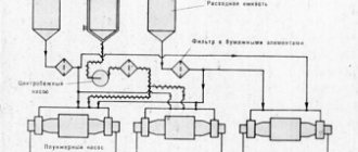
Gate valves with a gate design are used in treatment and filtering installations and various pipelines (usually of the “dirty” type). This means that durable and reliable dampers do an excellent job of blocking the movement of powerful mud flow. They can be installed on pipelines carrying high pressure
refers to rock, oil, all kinds of liquids with granules, pulp and other impurities, solid inclusions and particles.
Based on the diverse range of pumped media, gate valves are classified into models intended for use in various industries. In particular, the most popular areas of use of such valves are:
- chemical industry;
- oil and gas industry;
- production of building materials;
- public utilities;
- mining industry;
- pulp and paper industry;
- electric power and so on.
Gate valves, due to their ability to filter and crush particles passing through it, as well as to pass large volumes of working fluid, are widely used and used in sewer systems and drains. They are also quite in demand for chemical plants, where they are equipped with technological lines for the production of ammonia, mastics, acids and all kinds of mineral fertilizers. In the mining industry, gate valves help filter and dispense useful components, preparing them for subsequent processing.
A separate area of application, which is regulated by regulatory documentation GOST 55020-2012, is the oil and gas industry. In this area, gate valves are used on main pipelines as part of Christmas tree fittings
Where are they used?
The introduction of valves equipped with electric drives occurs regularly. Thus, the equipment has found its application in the following industries:
- Public facilities (fire fighting).
- In the production sector (regulation of gaseous and liquid media).
- When arranging systems operating in the petrochemical and oil industries.
- Housing and communal services (ventilation, heating, drainage and water supply).
Their use is due to the fact that it provides the opportunity to carry out installation work in hard-to-reach places and in places where large cross-section pipes are used, which is fraught with the formation of a high operating pressure. Carrying out any manipulations manually will be impossible.
Design of gate valves
The standard design of any gate valve involves the movement of the valve element perpendicular to the direction of flow of the pipe contents. All valves of this type, due to their use in large industrial areas, are made from materials that do not corrode and are also resistant to various temperatures, aggressive chemical environments and negative environmental influences.
Strict consumer requirements for these shut-off valves predetermine high quality standards for the manufacture of gate valves, which must be reliable, durable, strong and have a long service life (more than a dozen years). The main materials for the manufacture of gate valves are:
- cast iron or cast iron alloy with spheroidal graphite of high quality;
- steel (stainless, carbon, low-alloy);
- non-ferrous aluminum alloys;
- polyvinyl chloride (PVC);
Also, to extend the service life of metal plates, polyester, epoxy and anti-corrosion protective coatings are used.
The design of a gate valve includes the following main components:
- knife plate - gate;
- outer casing;
- seal element;
- stuffing box sealing unit;
- rack.
Additional parts used in the design of the gate valve mechanism are:
- threaded bushing;
- casing;
- pointer;
- spindle (rod);
- flywheel;
- oil seal cover;
- O-rings.
Installation recommendations
When installing gate valves in a pipeline, the following recommendations must be observed:
- Before installation, you should make sure that the connecting flanges are cleaned of dirt, scale, rust, and there are no scratches on them.
- You should also check the linearity of the pipeline - the valve is not designed to align it, and if it is installed at misaligned ends, there is a high possibility of leaks and even cracks in the body.
- Water hammer in the system, which can be caused by rapid opening of valve gates, should be avoided.
- It is advisable to tie the bodies of heavy shut-off valves with a soft tape sling. Under no circumstances should the valve be secured to the handwheel or actuator.
- During installation, you should avoid impacts and friction - this can lead to the destruction of the protective coating of the housing and its accelerated corrosion.
- Be sure to install the fittings along the arrow on the body, indicating the direction of movement of the transported flow.
- Gate valves are supplied with a loose gland. All bolts must be tightened before installation.
- The gate valve can be installed in any position with the exception of the vertical bottom.
- For heavy products of large dimensions installed horizontally, supporting supports should be provided.
Rice. 18 Installation rules
Gate valves are widely used in many industries and the national economy, where gases and clean or contaminated liquids are transported through pipelines and without them. Due to the wide range of uses, gate valves have a fairly large number of design options, materials for manufacturing the main components, which are bodies, gate valves and seals.
Operating principle of gate valve
The simple and at the same time reliable principle of operation of gate valves largely predetermined their high popularity and indispensability in the organization of pipelines, designs of production and industrial installations, as well as sewer and other systems. So, the valve is always installed perpendicular to the flow of the working medium (air, liquid, gas with various impurities and components). Under manual mechanical or automated influence, the force from the rod or spindle is transmitted to the gate element, which is driven and completely or partially blocks the passage of the contents in the pipe. At the same time, a spindle installed in a limited space may not have a retractable design. In this case, the tightness on both sides of the gate is ensured by the pressure of the working medium. Also, a tight and reliable connection is achieved through the use of an oil seal made of synthetic fiber, dry or oiled cotton fiber, as well as graphite and other materials.
A polished and sharpened gate, shaped like a knife or guillotine, performs a smooth sliding movement between the working medium and the seal. Such a device helps to avoid temporary delays in the operation of installations or pipelines. The sharp ends of the gate with a strong seal ensure smooth and uninterrupted operation of the valve, reducing the likelihood of premature wear of the main working element, especially in the presence of aggressive environments, as well as many large components and impurities.
Frequent errors and problems during installation
- Installation of a valve in an insulated area. Under the influence of thermal expansion, the damper may jam;
- Installation of a cast iron part in a metal chimney (cast iron weighs a lot);
- Using too thin steel or stainless steel with a low nickel content for the manufacture of valves. Such a product quickly deforms under the influence of hot gases and can burn out;
- Installation of a gate with a non-smooth surface;
- Installation of a valve without a hole for carbon monoxide release;
- Installation of handles that do not allow monitoring the position of the valve (applies to rotary elements).
Classification of gate valves
The valve body is one of its main parts, which protects internal elements from mechanical damage and external influences. The body shape can be made in the form of a cylinder or a rectangle. Various housing options for valves can be made either monolithic (single, solid), or in prefabricated or welded construction. Some manufacturers offer combined versions of protective housing parts.
Based on the type of gate valve installed (closing element), gate valves are divided into plate and plate gate valves. The group of shut-off valves with plates is also divided into “knife” and “guillotine”. The first type of valve with a gate valve in the form of a monolithic slab has in its design a hole into which a pipe installed on the opposite side fits. Knife and guillotine gates have a pointed shape in accordance with their name - in the form of a knife or a blade sharpened at an angle (like a guillotine).
The installed seal classifies the valves into metal/metal and metal/synthetic categories. The type of sealing element used is very important to create a perfectly tight seal when closing the valve. The following synthetic materials are used for the production of slide-type seals:
- nitrile rubber is a chemical-resistant material;
- ethylene propylene diene rubber (EPDM/EPDM);
- rubber mixtures with the main component SKN for hot environments;
- frost-resistant material Viton;
- silicone
According to the method of control and operation, the following types of dampers are distinguished: manual gate valve and gate valve with automatic drive. The manual type of control requires the presence of a mechanism with which you can adjust the position of the gate in the valve. The following mechanism is used:
- square or round nozzle;
- valve with flywheel;
- steering wheel with static or retractable stem;
- lever arm;
- T-shaped key.
Valves with automatic or mechanized control may have:
- pneumatic drive - allows movement in both one and both directions, and is also equipped with a manual override with adjusting bolts;
- hydraulic drive;
- electric drive – equipped with limit switches in the extreme positions of the knife-type gate;
- combined type drive.
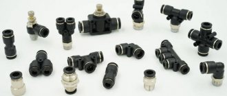
Based on the type of connection to the main pipeline, gate valves are divided into:
- flanged;
- wafer;
- welding
It should be noted that with any method of fastening, experienced installers additionally use wafer gaskets, bolts, studs and other connecting elements.
Specification
| № | Detail | Material |
| 1 | Frame | GG-25 |
| 2 | Knife | AISI 316 Ti |
| 3 | Seat seal | EPDM/Nitrile |
| 4 | Seal | Synthetic PTFE fiber |
| 5 | Oil seal cover | DN 50-300 – aluminum DN 350-1000 – malleable cast iron |
| 6 | Stock | AISI 303 |
| 7 | Weight nut | Brass |
| 8 | Yoke | Carbon steel with epoxy coating |
| 9 | Sleeve | Brass |
| 10 | Washer | Polyamide |
| 11 | Spring pin | Steel according to DIN 1481 |
| 12 | Steering wheel | Ø ? 310 mm: ductile iron/Ø? 410 : GG-25 (gray cast iron) |
Overall dimensions of ORBINOX TL valves with electric drive. DN 50-600
The motorized shutter mechanism consists of:
- Electric drive
- Retractable rod
- Yoke with seat for electric drive (in accordance with DIN 3338)
The standard electric motor is equipped with:
- Steering wheel for manual control
- Limit switches (open/closed)
- Torque switch
Additionally: it is possible to equip the shutter with a non-retractable rod with an electric drive.
Standard flange connection, PN 10. The length of the blind bolt is selected depending on the thickness of the counter flange.
| Du | Dimensions, mm | Weight (kg) | Rod diameter Ø x pitch | DR (bar) | |||||||||||
| A | B | C | D | E | F | ØG | H | I | J | L | M | ||||
| 50 | 40 | 152 | 100 | 110 | 129 | 382 | 160 | 552 | 265 | 249 | 62 | 237 | 9 | 20 x 4 | 10 |
| 65 | 40 | 167 | 100 | 115 | 146 | 404 | 160 | 574 | 265 | 249 | 62 | 237 | 10 | 20 x 4 | 10 |
| 80 | 50 | 182 | 100 | 124 | 162 | 429 | 160 | 599 | 265 | 249 | 62 | 237 | 11 | 20 x 4 | 10 |
| 100 | 50 | 202 | 100 | 140 | 187 | 470 | 160 | 640 | 265 | 249 | 62 | 237 | 14 | 20 x 4 | 10 |
| 125 | 50 | 216 | 100 | 150 | 211 | 504 | 160 | 674 | 265 | 249 | 62 | 237 | 20 | 20 x 4 | 10 |
| 150 | 60 | 241 | 100 | 175 | 237 | 555 | 160 | 1125 | 265 | 249 | 65 | 237 | 25 | 20 x 4 | 10 |
| 200 | 60 | 294 | 122 | 205 | 309 | 669 | 200 | 1289 | 282 | 256 | 65 | 247 | 44 | 25 x 5 | 10 |
| 250 | 70 | 356 | 270 | 245 | 364 | 764 | 200 | 1344 | 282 | 256 | 65 | 247 | 67 | 25 x 5 | 10 |
| 300 | 70 | 410 | 270 | 280 | 414 | 849 | 200 | 1434 | 282 | 256 | 65 | 247 | 82 | 25 x 5 | 6 |
| 350 | 96 | 473 | 270 | 300 | 500 | 930 | 200 | 1515 | 282 | 256 | 85 | 247 | 135 | 35 x 6 | 6 |
| 400 | 100 | 538 | 270 | 350 | 550 | 1030 | 200 | 1615 | 282 | 256 | 85 | 247 | 165 | 35 x 6 | 6 |
| 450 | 106 | 588 | 270 | 420 | 598 | 1193 | 315 | 1793 | 385 | 325 | 90 | 285 | 220 | 35 x 6 | 5 |
| 500 | 110 | 646 | 270 | 450 | 658 | 1283 | 315 | 1883 | 385 | 325 | 90 | 285 | 280 | 35 x 6 | 4 |
| 600 | 110 | 754 | 290 | 530 | 758 | 1443 | 315 | 2143 | 385 | 325 | 90 | 285 | 330 | 35 x 6 | 4 |
Main technical characteristics
Gate valves, regardless of the type of design and operating features, have high technical characteristics already in the basic configuration, which implies:
- compliance with the quality of the established standard according to GOST 24856-2014;
- optimal operation under standard operating pressure Pn: 10/16;
- good interchangeability of control drives;
- diameter (DN) in a wide range from 50 to 600 mm;
- maintaining operating temperature up to +80 degrees Celsius (short-term - up to 110 degrees);
- made from durable materials;
- long service life.
The established designations of dampers, as well as other fittings, according to GOST, oblige manufacturers to accurately indicate the name of the manufactured products according to the scheme: “type – type – type of design – pipeline diameter – name (or other parameters) of the model.”
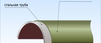
Frame
The valve body can be cylindrical or rectangular in shape. Be made monolithic or solid. Welded or prefabricated method. Based on some features of a narrow range of models, the gate and bottom cover can be removable based on precautions and design features of the selected equipment. The body is made of nodular graphite in combination with high-strength cast iron (possibly gray) or low-alloy carbon steel. Undoubtedly, the material used will affect the durability of the entire structure and the aggressiveness of the environment, if any.
Cast iron valves are considered to be of lower quality and durability compared to steel models. Thus, the surface of the housing copes well with motor oils, waste, diesel fuel and gasoline. If necessary, you can use a combined version, in which there will be a cast iron body, and the parts in contact with liquids will be steel. Epoxy coating will help cope with the possible consequences of corrosion.
Advantages of gate valves
The modern range of high-quality and multifunctional gate valves has an impressive list of advantages, among which the following points can be highlighted:
- simple and practical design;
- absence of zones with stagnant working environment;
- self-cleaning ability;
- minimal hydraulic resistance;
- class A tightness parameters;
- simple repair and maintenance;
- minimum requirements for operator qualifications;
- easy and quick installation;
- unpretentiousness to the working environment;
- relatively short construction length;
- long service life (more than 30 years);
- rare frequency of repairs and major maintenance - on average once every 5 years.
Gate valves are a necessary element for creating reliable pipelines or systems for pumping working media, including solid granules, various impurities and other similar components. High technical characteristics, simplicity of design and ease of operation, as well as the widest range of possible applications on a domestic and industrial scale - all this is the key to the great popularity of the products of the largest manufacturers of pipeline fittings around the world. Slide valves remain today one of the most reliable shut-off valve options with advanced unique capabilities.
Advantages and disadvantages of wedge devices
The advantages of wedge valves include providing an increased level of tightness of the flow area in the closed position, a simple operating principle, as well as a small amount of force required to connect the parts of the shut-off assembly with the maximum possible seal.
This is facilitated by the formation of an almost right angle between the directions of the drive force vector and the force vector acting on the plane of the sealing surface of the valve element. As a result, even a small force passing through the spindle can have a significant impact on the contacting surfaces of the seals.
The disadvantages of devices with this operating principle are:
- the need to equip the body cavity with guides for centering the wedge;
- rapid wear of seals on the valve;
- the complexity of the technology for obtaining tightness in the closing element.
Electric models
A gate valve equipped with an electric drive is one of the more modern shut-off devices, which are successfully used for work in process pipelines for industrial purposes and in housing and communal services. The electric drive is responsible for the timely closing and opening of the lock, holding it in an intermediate position if required by technology, and also automatically shuts off the valve in the event of an emergency. The electric drive control unit is mounted either on the unit body, or mounted in a special cabinet, on racks, or located in a remote location.
For details about the design and operation of the electric drive on the valve using the example of the URPS BEERS 13. NL series, see the video.
Design and principle of operation of an electrical apparatus
The drive mechanism is connected to the valve spindle using a special bushing and consists of an electric motor and gearbox.
The principle of its operation is as follows: when control signals are received, the engine acts through a transmission mechanism on the spindle, which in turn opens/closes the shutter or places it in an intermediate position.
Modern electric drives also include limit switches and a torque limiting clutch. They turn off the power to the electric motor when the bolt element reaches its extreme positions or when a force acting on the rod occurs above the set value.
The ability to limit torque when the valve is jammed or clogged helps prevent failure of the valve and actuator.
Thanks to this operating principle, on large highways it is possible to create a single control point for all valves equipped with an electric drive.
This method of controlling the shut-off body is very effective because it is reliable and has a long service life.
Attention! To shut down in the event of a malfunction of the electric drive or other emergency situations, the valve is equipped with a manual override - a flywheel.