When applying symbols to shut-off valves in the Russian Federation, TsKB standards are used. The Central Bureau has developed documents that contain an exhaustive list of products, with their brief description and numbers of legal acts. A brief description of the valves consists of an alphanumeric code. A total of five elements are used in the designation. How valves are marked and what the symbols used in the description mean, we will consider below.
What does the marking mean?
The term refers to the application of alphanumeric designations to shut-off valves for pipelines, gas and oil pipelines. This also includes graphic symbols of different types of products on hydraulic and pneumatic diagrams.
The symbols contain all the key technical parameters necessary for the sale and safe operation of products in various industries. The selection of the necessary reinforcement is done using a table of figures (ST TsKBA 036).
The numbers (1-2) immediately after the letters in the marking indicate the model number (design type). If the description has three numbers, the first of them indicates the type of shut-off valve drive (Table No. 3).
Control valves - Wikipedia
Material from Wikipedia - the free encyclopedia
The current version of the page has not yet been verified by experienced participants and may differ significantly from the version verified on March 21, 2015; checks require 4 edits. The current version of the page has not yet been verified by experienced participants and may differ significantly from the version verified on March 21, 2015; checks require 4 edits.
Control valves
is a type of pipeline fittings designed to regulate the parameters of the working environment. The concept of parameter regulation includes regulating the flow of the medium, maintaining the pressure of the medium within specified limits, mixing various media in the required proportions, maintaining a given level of liquid in vessels and some others. The control valves perform all their functions by changing the flow rate of the medium through its flow area.
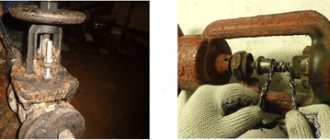
Depending on the specific operating conditions, various types of control valves are used, most often using external energy sources and control by command from sensors that record the parameters of the medium in the pipeline. Automatic control directly from the working environment is also used. In modern industry, it is rare, but still found, that the main way to control regulators in the past was manual control ( see figure on the right
).
Depending on the parameters of the working environment (pressure, temperature, chemical composition, etc.), different requirements are imposed on each type of regulation, which has led to the emergence of many design types of control valves. From the point of view of automation of industrial enterprises, each of them is considered as an element of an automatic process control system, occurring with the participation of liquid and gaseous working media and regulated under the influence of the received command information[1][2]
[3].
en.wikipedia.org
Types of markings
Manufacturers use a unified scheme for applying numbers and graphic images. This approach allows the end user to quickly understand the range of valves. Types of marking:
- Alphanumeric description of parameters.
- Applying special marks to the product.
- Appropriate color scheme.
- Description of the product according to the table of figures.
Marking signs are applied taking into account the requirements of GOST 4666. Each symbol on the valve body or plate contains specific information.
Main characteristics
Increased demands are placed on products that fall into the category of gas valves, check valves or shut-off valves, since they are constantly in contact with an aggressive working environment that continuously moves inside the installed system. All basic standards and requirements are given in GOST No. 95-44-93. These are exactly what all domestic manufacturers adhere to in the process of manufacturing their own products.
Often, carbon steel is used as the main material, which is characterized as a high-quality material that is resistant to corrosion. Wrought iron, bronze or brass can also be used (in terms of cost, they are more affordable). The tightness of products is checked at the stage of their manufacture, after which, in accordance with existing norms and standards, they will be assigned a certain tightness class.
GOST No. 27-85-70 regulates what designations should be applied to the body of the product. The labeling must contain the following information:
- main material;
- manufacturer;
- diameter;
- pressure;
- direction of movement.
GOST 4666-2015
The state standard defines the alphanumeric description and status of marking symbols. Types of symbols:
- Required. Can be applied to all types of valves and actuators.
- Additional. Applied to some types of fittings according to the manufacturer's decision. Plus if the application of such information is provided for by the contract or regulations.
- Special. They are applied to the fittings in accordance with the requirements of technical regulations, directives or safety regulations. Special signs are usually placed on a separate plate.
On a note! Additional symbols are mandatory for certain sectors of the national economy. For example, nuclear energy, oil and gas industries.
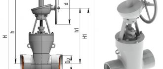
Device type, symbols
On the outside of the fittings, the working pressure and the nominal size of the passage, the index - type, and basic data are indicated. The coding is applied in the form of casting or branding. The second marking method, the most complex, is rarely used.
Legend - product type:
- trial pass – 10;
- pipeline – 11;
- locking product – 12;
- valve – 13-15;
- receiving pipeline, return lifting with filter – 16;
- fuse – 17;
- turn-reverse – 19;
- pressure regulator “before and after” – 21
- shut-off – 22;
- regulatory – 25;
- mixing – 27;
- valve – 30, 31;
- bolt – 32;
- condenser drain – 45.
The use of markings allows you to correctly select the device, use the fittings for their intended purpose, and increase the possibility of control during installation. Conventions help make decisions during production processes.
TsKBA standards
The Central Bureau has developed its own standards - TsKBA 023-2015 and TsKBA 036-2017. The first document defines the rules for the conditional description and registration of a table of figures. The manufacturer cannot establish mass production of locking products of its own design without the permission of the Central Design Bureau. Any other manufacturer can use a figure table registered with the bureau. The only requirement is that the manufacturer must indicate the letter “M”, “M1”, etc. at the end of the table. The new table of figures must be re-registered with the Central Design Bureau.
The second document serves as reference material for describing the valves and drives to them according to design documentation and tables of figures that have been registered with the bureau. The standard includes a complete list of products, with their conditional description and numbers of regulatory acts for the manufacture of products. The document is formatted in tables. They contain:
- mini-description of the product;
- designation according to tables (1, 2, 3);
- nominal pressure (kgf/cm²) and diameter (DN);
- description of products according to design documentation;
- TU or GOST for production and supply;
- drawings for each table.
Rice. 2. Table of figures
Each new model of released fittings is entered into the TsKBA standard 036-2017. In this case, the used table of figures must be indicated. Procedure for obtaining permission:
- The manufacturer submits an application to the bureau for registration of manufactured products. It must contain the technical parameters of the shut-off valves, the document number (TU), on the basis of which the product was manufactured.
- Bureau employees check the package of documents. Sometimes Central Design Bureau employees visit the workshop and inspect the valve production and assembly line.
- Products are registered in the Central Design Bureau directory.
A sample application for registration can be found in ST TsKBA 036-2017.
Shut-off and control valves (general information and types) | Pipeline accessories
Rating: / 4
Flow control in pipeline systems, lines and sections is carried out using devices collectively called pipeline fittings.
Fittings also include connecting elements of pipelines - flanges, tees, couplings, etc. Shut-off and control (pipeline) valves are devices designed to shut off or distribute the flow of a medium, regulate various parameters of technological processes (pressure, head, temperature, amount of supplied substance, etc.). Regulation of technological processes is carried out by changing the flow rate of the transported medium.
Pipeline fittings are mounted on pipelines, tanks and other units in which it is necessary to disconnect, distribute or regulate the flow of transported or used media.
According to their functional purpose, pipeline fittings are divided into types, the main ones being (according to GOST R 52720-2007 Industrial pipeline fittings):
- shut-off valves,
- control valves,
- shut-off and control valves,
- protective fittings,
- safety fittings,
- mixing fittings,
- phase separating fittings.
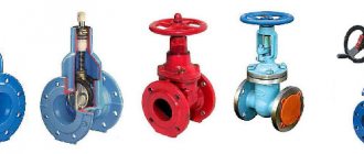
Shut-off valves
As the name suggests, shut-off valves are designed to completely shut off the flow of medium in a pipeline. This is the most common type of pipeline fittings. More than 80% of all valves are shut-off valves.
Control and shut-off and control valves
Control valves are designed to maintain the required values of certain parameters of technological processes by regulating the flow of the working medium. The main controlled parameters are temperature, pressure, composition and concentration of substances involved in the process. In design, it is similar to a shut-off valve, and often the same types and even brands of pipeline fittings can and are used both as control and shut-off valves.
Control valves also include throttling valves, which are designed to significantly reduce the pressure of the medium and operate under conditions of large pressure drops.
Safety and protective fittings
Safety and protective fittings are designed to eliminate the negative impact on the equipment of the working environment in case of exceeding the permissible values of pressure or direction of flow of the working environment.
The difference between safety valves and protective valves is that when an emergency condition of an environmental parameter occurs, the safety valve opens to release an excess amount of the working environment, and the protective valve closes, cutting off the protected section from the rest of the pipeline, which protects it from unacceptable influences.
Mixing fittings
Distribution and mixing fittings, designed to distribute the flow of the working medium in certain directions or to mix the flow of the medium, are used mainly in heating systems to achieve the required coolant temperature by mixing incoming and return water.
Phase separating fittings
Phase separating fittings are designed for automatic separation of working media depending on the phases and state of these media.
The connection of the fittings to the pipeline can be carried out using couplings with internal threads, pins on external threads with a seal, nipples, using flanges or welding.
Welding is one of the most reliable methods of connecting elements of a pipeline system; in addition, when using high-pressure fittings, a welded connection becomes the only possible one.
Flanges are a flat ring or disk with holes for bolts and studs; they are made mainly from carbon, alloy and stainless steels and other metals. Flanges as separate parts are most often welded or screwed to the ends of the parts being joined, although often the flange may be part of the part or pipe itself.
Tests for the tightness of pipeline fittings, for the strength of the body, components, parts - checking the compliance of the object with the established technical requirements must be carried out before installation on the pipeline. Ideally, this should be done by a product supplier who provides a guarantee of the quality of their products.
www.podvod.ru
Graphic symbols
Graphic symbols of different types of fittings on hydraulic diagrams are regulated by GOST 2.785-70. The interstate standard covers all sectors of industry and construction. The exceptions are hydraulic and pneumatic drives, and products of the aviation industry.
On a note! The interstate standard does not regulate the sizes of graphic symbols. The manufacturer has the right to combine symbols based on the type of connection and type of valve control.
Where are they used?
There are many areas where such equipment is used. They can be roughly divided into the following subgroups:
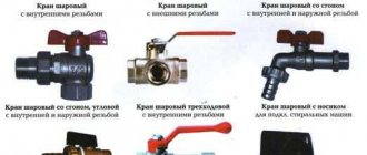
- Household sanitary products. This area is rightfully considered one of the most extensive. Such fittings are used in the construction of water supply systems for both apartment and private houses. Installation is also carried out both in heating systems and gas stoves. Often, a manual control type is chosen, since their performance indicators are at the optimal level. They are also very reliable and have their own designation (check valves).
- Fittings that are commonly used in the design of river and sea vessels. This type of product is very specialized; in addition, equipment of this type should weigh little and be characterized by a high level of reliability.
- Pipe shut-off valve type, which is used on an industrial scale. This category includes fountain equipment, systems responsible for transporting radioactive and toxic masses, and the oil industry. Products used in these areas must be characterized by a high level of reliability and an appropriate service life. Resistance to corrosion is required, as is tolerance to sudden temperature and other changes (pressure).
- Fittings intended for general use. This type of fittings can be found in absolutely every area of daily activity of a modern person. This applies to both domestic and commercial use (purpose). So, examples include boiler rooms, water supply systems, gas pipelines and heating systems. All shut-off valves for water supply should also be included in this category.
Marking methods
Manufacturers use different methods of applying symbols. Among them:
- Casting.
- Engraving.
- Impact method.
The manufacturer may use other methods of applying symbols to manufactured products. The only condition is a clear image throughout the entire service life of the product.
Requirements for applying symbols are described on the drawing of a separate part or on the assembly drawing of the marked product (clause 4.3.5 of GOST)
Shut-off and control valves: types and purpose of devices
Any system periodically requires shutting down some areas, for example, for inspection or maintenance. To do this, shut-off and control valves are installed in the pipelines, with the help of which it is possible not only to block the movement of the working medium in the pipes, but also to regulate the optimal values of the operating parameters to maintain its high-quality operation.
Characteristics and purpose
Shut-off and control valves are devices that are designed to shut off, change and control the parameters of the internal environment of a pipeline. Such fittings are installed in water supply, heating, sewerage and gas supply systems.
The devices are used at all levels: from large highways to individual pipelines located inside a house or apartment.
Each system has several parameters that can be adjusted. These include volume and flow rate, pressure, temperature. Shut-off and control valves are used to allow these parameters to be changed without shutting down the system.
The purpose of such parts is to redirect the flow of liquid or gas to other branches of the system. To do this, the device is installed in a place where there are branches. As necessary, some branches are closed and others are opened.
Other types of shut-off and control valves are capable of reducing the pressure inside the system if it increases or decreases the temperature. Some of them work automatically, according to the laws of physics.
For example, a release valve allows gas to flow only when the pressure inside the system increases. This allows you to keep this parameter at the same level. Other devices are manually adjusted, for example using valves.
The main characteristic of shut-off and control valves is its throughput. For optimal application, relative, actual, maximum, initial and conditional throughputs are calculated.
Note! Throughput is a physical quantity that reflects the volume of a medium of constant density passing per unit time through a cross-section of a pipe at a pressure of 1 bar. Simply put, it is the amount of liquid or gas that can pass through a pipe in a certain period of time.
In addition, shut-off and control valves are characterized by the range and zone of regulation, as well as the setting of the regulator. These parameters reflect the differences between the maximum and minimum throughput data: the range of values that can be adjusted.
Another important characteristic is relative leakage. It reflects the theoretical ability of parts to deviate from the specified tightness parameters. Simply put, this is a quantitative reflection of the leakage of the product.
Requirements for shut-off valves
Shut-off and control devices, regardless of whether they are installed at the end consumer or on large highways, are subject to a number of general requirements. They are taken into account during design.
Each of these requirements is guaranteed, that is, it has certain deadlines and deviation parameters. The manufacturer guarantees that if installed correctly, the requirements will be met and deviations in operating parameters will not exceed the specified values.
Requirements for shut-off and control devices:
- Regulation accuracy. The part must operate exactly within the specified values. For example, per unit of time, pass only the volume of liquid that is specified or maintain a specified pressure inside the system. Deviation of these parameters from the specified ones indicates a malfunction of the fittings.
- Strength. The device must not be deformed before it is installed in the system and must be resistant to mechanical loads. Strength determines the longevity of the part.
- Temperature and chemical resistance. These requirements are not necessary for all types of products. In the heating system, it is important to install parts that can function at high temperatures, and for cold water supply, this parameter can be omitted. Chemical resistance is important where the internal environment is chemically active, i.e. it entirely depends on the properties of the materials from which the device is made.
- Tightness. There are two types of tightness: relative to the external and relative to the internal environment. All devices must be completely sealed with respect to the external environment. This means that there should be no leaks of liquid or gas into the external environment at the places where they are installed. Tightness relative to the internal environment reflects the possibility of redistribution of liquid or gas on both sides of the valve outside the specified parameters, for example, if a certain amount of liquid passes through the shut-off valve into that section of the pipeline that is disconnected from the system.
- Durability. Each type of fittings, depending on the design features, the material from which it is made and operating parameters, has its own warranty period. Since replacing shut-off valves and valves is somewhat difficult, preference should be given to the most wear-resistant parts.
Note! Most types of shut-off and control valves, when used correctly, can last at least 30 years, although manufacturers provide a guarantee for a shorter service life.
- Easy to use. All areas of the system must be periodically checked, repaired, and cleaned. The part should be simple enough to reduce maintenance effort.
Types of shut-off and control valves
Locking and regulating parts differ in purpose and method of operation.
There are three types according to their purpose:
- Exclusively shut-off valves are used to block the flow of liquid or gas. The valve has two positions: it allows the flow of the internal medium to pass through and does not allow the flow of the internal medium to pass through.
- Exclusively regulatory. They cannot completely block the flow, only regulate its parameters.
- Locking and regulating parts. The extreme positions of the valves correspond to shut-off positions, that is, they either allow or do not allow liquid or gas to pass through. The intermediate positions correspond to the regulatory ones - they allow the internal environment to pass through in accordance with the specified parameters.
Shut-off and control valves, in turn, are divided into several types:
- Seat valve. It is most often used on large main pipelines. The plunger serves as a moving part inside such a valve. This is a piston that is able to move, thus regulating the flow parameters.
- Ball devices. Inside such parts there is a ball with a through hole. It is capable of turning 900 around its axis. When the hole is parallel to the flow, the medium passes through the device; when it is perpendicular, it does not; intermediate values determine partial throughput.
- Wedge fittings. Inside this part there is a wedge that moves perpendicular to the flow of liquid or gas. The principle of its operation is similar to the principle of a damper, which moves from top to bottom. At the highest possible position, the entire flow passes through the fittings; when completely lowered, nothing passes through. Intermediate positions allow some liquid or gas to pass through.
- Rotary disc devices. They are a valve that looks like a disk to which a control valve is attached. The diameter of the disk corresponds to the cross-section of the reinforcement. If the disk is located perpendicular to the flow, the liquid does not pass through, if it is parallel, all of it passes through. Intermediate positions are adjustable.
Shut-off and control devices for heating systems
Heating systems differ from other systems, which use devices that can operate at high temperatures. The material from which the parts are made must have significant heat resistance, for example, stainless steel or bronze.
In different areas of the heating system, shut-off and control devices, only shut-off or only control devices are installed.
Each of them has its own purpose:
- Taps are needed where the pipe has branches. Using a tap, you can completely or partially redirect the coolant flow to another direction or shut off the main line.
- The Mayevsky crane is an improved ball device. It is needed to bleed air from the system. When closed, it creates a completely sealed barrier, and when open, it allows only air to pass through.
- Check valves are installed on pipes where unwanted backflow of coolant is possible. They allow liquid to flow only in one direction along the flow and prevent it from returning back.
- Mixing units allow you to mix cold and hot water. The temperature in the distal section of the pipe depends on the position of the valve.
infotruby.ru
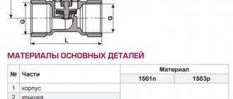
Components of the marking
On the valve body there is a mark in the form of the TsKBA system index.
Rice. 3. Marking
| Gate valve model | 30s41nzh Ru16 Du150 | 30ch39r Ru16 Du50 | 30ch6br Ru10 Du100 |
| Housing material | Carbon steel | Gray cast iron | |
| O-ring material | Stainless steel | Rubber | Bronze and brass |
| Digital description of the valve type | 30 | 30 | 30 |
| Letter description of case material | WITH | H | H |
| Letter description of O-ring material | NJ | R | BR |
| Table of figures (sealing material) | 4 | ||
| Valve drive type | Mechanical with spur gear | Manual | Pneumatic |
| Digital description of the drive type | 4 | — | 6 |
| Teak designs | 41 | 39 | 6 |
| Reinforcement diameter | 150 mm | 50 mm | 100 mm |
| Working pressure (kgf/cm²) | 1.6 MPa (16 Bar) | 1.0 MPa (10 Bar) | |
Content
Items that the marking of shut-off valves must reflect/contain according to GOST .
- Information about the manufacturer (name, brand);
- Dimensional characteristics: Nominal diameter (nominal diameter). Designated as DN + numbers, indicated in mm.
- Conditional pressure (nominal Pu/PN + working), in MPa.
- steel (NS – stainless, LS – alloy);
- p – rubber surface;
The color of the surfaces of product parts should also be considered as part of the marking of shut-off valves. The following distribution applies here, according to GOST marking of shut-off valves :
- blue indicates the use of alloy steel;
- black – body and elements made of cast iron (gray, malleable);
- blue – corrosion-resistant steel;
- gray – carbon steel.
Marking of shut-off valves
Symbols are applied to the valve body in accordance with GOST 4446. They contain:
- Passage diameter. It is indicated in millimeters. Example: in the description the letters and numbers “DN250” or the numbers “250”.
- Nominal pressure. The unit of measurement is “kgf/cm²” or “bar”. Example: the description contains the letters and numbers “PN25”. Pressure can also be indicated in MPa. But then a postscript is made: “PN2.5MPa”.
- Case material. A brief description of the alloy is displayed here. For example, a steel valve is “25L” or “WCB”.
- Manufacturer's logo. The use of an abbreviated name is permitted. Example: CJSC "SibZTA".
- Date of manufacture of fittings. Several application options are allowed. Example: "08/2015", "08/2015" or "August 2015".
- Factory number. Example: "77" or "No. 77". Sometimes manufacturers indicate the number and date of manufacture. The marking looks like this: “04.2015 – 77”, “04.2015 – No. 77” or “77 – 04/15”.
- Direction of rotation of the steering wheel. It is displayed in the form of arrows on the flywheel (← closed or open →).
The manufacturer may also add additional symbols:
- Description of valves according to design documentation.
- GOST or TU, according to which the shut-off valves were produced.
- Data on acceptance of quality control department.
- Standard shutter position.
- Weight of the locking device.
- Climatic performance.
- Gasket type (PON-B, CIS, TRG). The description is applied to the edge of the flange.
On a note! Mandatory symbols are applied to the body of the product being marked. It is also possible to repeat the data on the plate.
The front side displays the product diameter, pressure and body material. On the back there is information about the manufacturer, production number and date, temperature range. If the dimensions of the valve allow, then all data is displayed on its front side.
Separate markings are applied to the electric drives of the valves. Metal plates are used for this. They are attached to the engine housing.
Rice. 4. Label on the electric drive
Regulating valves: types, parameters, purpose
Control valves represent a wide range of functional structures designed to distribute flows and shut off working liquid media, and regulate the parameters of individual technological processes. In particular, changing the parameters of pressure, temperature, pressure, and the amount of supplied substances is carried out by changing the flow rate of the transported media. Control valves are installed in pipeline systems, tanks and units where distribution or shutdown of used or transported media is required.
Main types of fittings
- Regulating valves - the main purpose is aimed at regulating the specified parameters of working environments. Includes all kinds of bypass, balancing and pressure reducing valves.
- Shut-off valves - used to shut off flows when moving working media. Among the most common types of shut-off valves are: gate valves for shutting off liquid flows, ball valves, wedge-shaped gate valves, valves.
Control valve elements
Regulating valves operate on the basis of the following elements:
- control valves;
- mixing valves;
- control valves;
- direct acting pressure regulators.
Purpose
Control valves are used to support the required, set values of certain technological processes by regulating the flow of specific working media.
According to the design, control valves are practically indistinguishable from shut-off valves. In some systems, the same control valve can be used for its intended purpose and as a shut-off valve.
Types of control valves
- Photo-separation – used when it is necessary to separate working media that are in different states.
- Condensation – used to eliminate condensation, limited passage or blocking of superheated steam flows.
- Protective shut-off and control valves are aimed at automatically protecting pipelines and equipment from unforeseen or unacceptable changes in the functioning of the pipeline system.
- Control room – designed to control the flow of working media into measuring and control devices.
- Mixing and distribution - distributes separate flows of working media in various directions or is directly involved when it is necessary to mix them.
- Throttling - used when it is necessary to reduce the pressure of working media in systems that operate under conditions of significant sudden pressure drops.
- Non-return valve is a check valve in which forced opening, restriction or closing of the stroke is possible.
Features of choice
Since in most cases the efficiency and high stability of the entire pipeline system depend on the level of reliability and durability of the fittings, the most important point is its choice. The following points should be paid attention to:
- Adjustable fittings should be selected based on the determining operating conditions: the nature of the working environment, temperature, pressure indicators in the system.
- When choosing control valves, it is important that its characteristics correspond to the nominal diameter of the passage.
- Before deciding to purchase a valve, it is necessary to clarify the method of its control: remote, manual, based on an electric, hydraulic or pneumatic drive.
- Initially, you should decide on the material for making the case: cast iron, corrosion-resistant steel, bronze, etc.
- Fittings are purchased depending on the purpose of individual elements: adjustable or safety valve, valve, gate valve.
- Important are the geometric parameters that distinguish control valves: length, height, types of flanges, dimensions and number of bolts, etc.
- It is necessary to check in advance the compliance of the characteristics and parameters of the selected fittings with the specified requirements and operating conditions of the pipeline system.
fb.ru
Requirements for product labeling
Letters and numbers on the reinforcement must be applied without tilting. The font size and arrows (casting) are indicated in accordance with Appendix “D” to GOST 4446. If the engraving method is used, then the requirements of GOST 26.008-85 must be taken into account.
When using other methods of marking on reinforcement, you must be guided by the provisions of GOST 2930-62.
Conventional symbols are applied on both sides of the product. The front part is considered to be the right side of the valve body. It determines the direction of flow of liquid, oil or gas. If such data is missing, then the front and back sides of the product are determined in the design documentation (clause 4.2 of GOST 4446).
Some information can be printed on flanges and connecting pipes. For example, on the body flange - 6, on the body-cover connection flange - 4, 8, 10-22.
If the valve diameter is less than 50 mm, then optional symbols can be applied to the tag or information plate.
What are shut-off and control valves used for in water supply systems?
The content of the article
To tightly shut off the flow of water, in addition to shut-off valves, shut-off and control valves can be used. It is an inseparable part of heating and water supply systems.
Shut-off and control valves
Shut-off and control pipeline valves combine the basic characteristics of control and shut-off valves and are used to control flow, compliance with specified parameters, and correct mixing of liquids and gases.
Main types of shut-off and control valves
Shut-off and control valves are used for heating and water supply systems, steam systems, as well as in industry for petrochemical, chemical and pharmaceutical enterprises, where they perform the task of regulating the flow of liquid, steam or gas. The following types of devices are distinguished:
- Saddle.
- Ball.
- Wedges.
- Slide-knife.
- Rotary disc.
Shut-off valve device
General characteristics of globe valves
Saddle fittings can be used for heating and water supply systems both for the purpose of regulation and limitation, and as a shut-off valve. The main types of saddle fittings include the following components:
- Packed shut-off valves;
- Angular;
- Bellows;
- Regulatory;
- High pressure valves;
- Boiler blowdowns.
The design of the saddle valve body is made in various versions depending on the type of connection, which is necessary for engineering systems. Valves are available with the following connection options:
- Coupling;
- Flanged;
- Threaded;
- Welding.
Bellows fittings
There are different types of saddle fittings depending on the material of manufacture. The main varieties include a body of:
- Gray and ductile iron;
- Cast steel;
- Of stainless steel;
- Bronze.
A wide range of operating temperatures (-60 - +450 ˚С) allows the use of seat valves for heating and hot water supply systems.
Durable and chemically resistant materials that are used to manufacture the shut-off valve allow the use of such components in both neutral and aggressive liquids and gases. This is the most profitable option for shut-off and control valves in terms of cost and technical capabilities.
Characteristics and features of the use of ball valves
In ball devices, the movable part of the shutter plays the role of a regulatory element. Such devices are used for plumbing systems and include the following types:
- High pressure ball valves;
- Three-way regulating;
- Industrial;
- Ball valves equipped with metal seats.
Ball Valves
The main advantages of ball valves, which distinguish them favorably from other types of shut-off and control valves:
- Minimum hydraulic resistance;
- Device reliability;
- Ease of operation;
- Performance;
- Suitable for fire and explosive, toxic and aggressive environments.
Ball valves can have various designs of end elements and connections, namely:
- Threaded;
- Flanged;
- Welded.
Ball valve device
Ball valves can be equipped with electric or pneumatic actuators to automate the process of adjusting the water flow. The convenience of ball valves is their long service life and minimal maintenance.
Wedge valves as flow regulators
Wedge valves are characterized by perpendicular movement of the control element in relation to the flow of liquid or gas. Wedge valves can be used for water supply, heating, gas supply systems, as well as oil pipelines, technological and transport pipelines. Key features of the device include:
- Possibility of operation in any conditions;
- Simplicity of design;
- Reliability;
- Wear resistance;
- Low hydraulic resistance;
- Service life is up to 30 years.
Wedge valves
The disadvantages of wedge valves for heating include:
- Long valve closing time;
- Difficulty in carrying out repair work.
Although there are options for gate valves, these are still rare. Most often, wedge valves are used as exclusively shut-off valves, which operate in two positions - open and closed.
Knife gate shut-off and control valves
Gate valves are equipped with a flat-shaped locking element - a gate. Depending on the type of construction, there are:
- Single disc valves;
- Double disc.
This type of shut-off and control valves is used for work in difficult working environments - for wastewater processing, water purification, processing of mineral raw materials, chemical products. The main advantages of gate valves:
- Minimum maintenance requirements;
- Full bore;
- Easily replaceable ring elements;
- Complete isolation of the gate knife from the solution flow in the open position.
Knife gate valves
Characteristics of butterfly valve
A rotary disk is used as a locking and regulating element. Dampers are widely used in heating, water supply and air conditioning systems. The operating medium of the damper can be process or treated water. The main elements of this device are:
- Frame;
- Disk;
- Upper shaft;
- Lower shaft;
- Saddle;
- Bearings;
- Lid;
- O-ring;
- Thrust ring;
- Pinch bolt;
- Key;
- Liner;
- Nuts and washers.
Butterfly valve
The main advantages of this device are:
- Low cost;
- Easy to operate and maintain.
Disadvantages of the butterfly valve:
- Sensitivity to pressure changes;
- Limited ability to regulate the flow of working fluid.
Technological process of operation of shut-off and control valves
| Author | Share | Rate |
| Victor Samolin |
Interesting on the topic:
vseotrubax.com
What color is applied and why?
Marking is not the only condition in the manufacture and use of valves. The body and lid are painted in a specific color. It depends on the type of metal used in the manufacture of reinforcement (Appendix “E”):
- Malleable and high-strength cast iron – black.
- Carbon steel - grey.
- Alloy steel – blue.
- High-alloy steel, heat-resistant and heat-resistant alloys - blue.
Rice.
5. Painting of valves When painting pipeline fittings for a gas pipeline, you must be guided by GOST R 56001-2014.
When painting valves for main oil pipelines, the requirements of GOST R 55020-2012 must be taken into account.
The manufacturer has the right to change the paint color at the request of the customer. It is also possible to supply unpainted products. However, the body and lid of each product are primed with a special composition.
On a note! The valve markings must not be filled with paint. The applied marks must be distinguishable after all types of processing of the product.
Examples of valve markings with explanations
Let's consider options for marking a wedge valve with decoding. As an example, let's take valve 30s927nzh. Its markings have the following meanings:
- “30” - indicates that the valve device is a valve;
- “c” — body material carbon steel;
- “9” - an electric drive is used to control the valves;
- “27” - serial number of the product assigned by the design bureau;
- “Нж” - indicates that sealing rings are used, onto which stainless steel is fused.
If there is an internal coating of the passage hole of the valve, its marking is supplemented by the designation of the material of such coating. For example, for the case under consideration, the marking 30s927nzhft will indicate that the passage hole is covered with fluoroplastic.
Seal material and internal coating method
The quality of labeling is the reputation of the manufacturer, a sign of a responsible approach to the nomenclature.
Letter coding – sealing material:
- brass, bronze - BR;
- stellite – ST;
- Babbitt – BT;
- Monel metal – MN;
- sormite – SR;
- stainless steel - NJ;
- skin – K;
- rubber seal – P;
- nitron steel – NT;
- vinyl plastic - VP;
- plastic – P;
- ebonite – E;
- fluoroplastic - FT;
- without a ring - BC.
Method of applying coating inside the device (letter coding): gumming - GM, plastic lining - P, enameling - EM.
Digital coding of product drives
Marking of pipeline devices is a regulatory measure that must comply with standards and GOST standards.
Drive – digital index:
- fur. with worm feed – 3;
- fur. with cylindrical feed – 4;
- fur. with conical feed – 5;
- pneumatic – 6;
- hydraulic – 7;
- electromagnetic – 8;
- electric – 9.
Labeling must meet several requirements: compactness and information content. According to state standards, coding is applied at the last stage of production, before testing. This allows you to eliminate defects and transfer products for sale for further use.