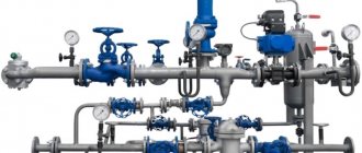
Shut-off valves, which allow the passage of the medium to be blocked if necessary, are installed on any pipeline, regardless of its type and purpose.
According to the installation method, shut-off valves are divided into threaded, flanged and welded
In domestic pipelines, threaded fittings are most often installed, in industrial pipelines - flanged fittings. Welded devices have hardly been used lately.
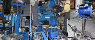
Parts of fittings of any type wear out during operation, as a result of which their size and shape change. Extreme wear leads to device failure. To restore functionality, repair of the shut-off valves is required.
The need for the latter may also arise as a result of a sudden failure caused by jamming of moving joints, jamming of the shutter, breakage of drive parts, etc.
Valves.
The technological operating mode of the valves, indicating the type of control (local or remote), the pressure drop across them and the maximum operating pressure are established on the basis of design documentation.
Operation of valves with a half-closed shutter is prohibited. The exception is emergency situations at the oil pumping station, when valves can be used for a short time to throttle the pressure.
Once per shift, the duty personnel conduct technical inspections of shut-off valves, during which the following are checked:
- tightness of flange connections and gland seals;
- smooth movement of moving parts;
- serviceability of the electric drive.
As part of maintenance, the following work is performed once a month:
- minor repairs to valves that do not require a special stop of main pumps (cleaning external surfaces, eliminating oil leaks, maintenance of sites, etc.);
- visual check of the condition of all parts of the valves;
- checking the presence of lubricant in the electric drive gearbox and replenishing it;
- checking the tightness of the stuffing box and flange connections;
- checking the functionality of the electric drive (terminal fastening, overload protection, operation of limit switches and torque limiting clutch);
- control of seal tightness.
To ensure the tightness of flange connections, they are tightened twice a year (in spring and autumn). The same procedure is followed if a leak is detected in the flange connection.
Tightening of flanged connections of valves must be carried out at a pressure reduced to a safe level. It must be borne in mind that before tightening the flange connection of the body and the cover of the wedge valve, it is necessary to open the wedge slightly to avoid damage to the threaded bushing.
Determination of the torque of the electric drive of the valve is carried out by measuring the current strength of its electric motor. Its value should not exceed the nominal value by more than 10%.
When carrying out seasonal maintenance, the valve seal is checked for tightness once every 6 months. It is combined with planned stops of the main pipeline and oil pumping station.
To control the tightness of the valve, a pressure difference equal to 0.1-0.2 MPa is created with an excess pressure of at least 0.4 MPa. The criteria for assessing tightness are the change in pressure in the cut-off sections of the pipeline and the presence of noise of leakage of the pumped liquid through the valve.
The change in pressure in the cut-off section of the pipeline is monitored according to the readings of pressure gauges (not lower than the first class of accuracy with a division value of no more than 0.05 MPa) in no less than 30 minutes. The valve is considered leaky if the pressure change in half an hour is 0.1 MPa or more.
The noise of leakage of the pumped liquid through the valve is recorded using acoustic devices (leak detectors, sound level meters). The detection of such noise in the valves of the pump connection unit to the main pipeline, the discharge and suction lines of the main pumps (aggregate valves), the SOD start-up and receiving chamber, and the inlet-dispensing pipes of tanks indicates that the valve is leaking. In other cases, leaks should not exceed the permissible value determined by the tightness class of the valves.
The criteria for their inoperability are:
- Leaks that cannot be eliminated by additional tightening through the stuffing box seals and flange connections;
- leakage of the pumped medium in the valve exceeding the permissible value;
- jamming of the moving parts of the valves when opening and closing the valves;
- increase in response time beyond the permissible limit;
- failure of the electric drive.
Inoperative valves are repaired.
Information on how to troubleshoot their possible malfunctions is given in the table below.
Repair of shut-off valves
Repair, as well as installation/dismantling of a butterfly valve or other type of fittings, is simple. However, errors are possible here too - especially in cases where the installer has not previously encountered the work of installing, assembling and disassembling shut-off valves. Often they try to seal the flange connection using additional rubber gaskets or welding, which is strictly forbidden.
]ARMATEK[/anchor] is ready to train installers working with shut-off valves of our production and provide repair kits for any model of butterfly valve or other shut-off devices.
If the shut-off valves are serviced in accordance with the regulations, the need to use repair kits rarely arises - they are unlikely to be needed earlier than after 6-7 years of operation.
Possible malfunctions of valves and ways to eliminate them
| Malfunction | Possible reasons | Remedies |
| Medium leakage when valve is closed | You break the seal due to wear or contamination of the surfaces of the sealing rings of the body and the wedge or disk. Insufficient force on the flywheel (less than calculated). Insufficient torque developed by the electric drive. Formation of solid particles or resin in the lower part of the housing | Disassemble the valve, clean, lap or replace the O-rings. Increase the force on the flywheel to the calculated value. Check torque clutch setting. Check the voltage at the input. Check the technical condition of the electric motor. Disassemble the valve and remove sediment |
| Passing the medium through the housing-lid connection | Loss of tightness due to insufficient tightening of bolts. The gasket is damaged. The sealing surfaces of the housing or cover are damaged | Tighten the bolts evenly. Replace the gasket. Remove the cover, repair the damage and rub in the sealing surfaces |
| Passing the medium through the stuffing box | The stuffing box packing is not tight enough. Wear of the stuffing box. Spindle surface damaged | Tighten the oil seal nuts evenly. Refill the oil seal or replace the packing. Repair spindle surface damage |
| Moving the shutter with delays or increased torque | The wedge or disc guides are damaged. Formation of solid particles or resin on the guides | Disassemble the valve and repair the damage. Disassemble the valve and remove sediment |
| Increased torque on the flywheel required for closing | There is no lubrication in the moving joints | Lubricate moving joints |
| The electric drive does not work | No power to the electric drive | Check and correct the power supply line of the electric drive |
Pressure regulators. When servicing pressure regulators, which is performed by maintenance personnel once a month, the following work is performed:
- external inspection to check the tightness of the housing and connections;
- checking the tightness of the stuffing box seals and, if necessary, tightening them;
- monitoring the integrity and serviceability of the shaft, drive levers, and gearbox;
- checking the presence of lubricant in the electric drive and gearbox (replenish if necessary);
- checking and tightening contact connections of the electric drive.
For the pressure regulator block as a whole, the following are produced:
- control of the accuracy and synchronism of damper operation;
- checking the functioning of the block heating system.
Kinds
Depending on the method of regulating the flow of the medium, shut-off valves are divided into devices of various types:
- Cranes are a universal device for regulating or distributing the working medium in pipes. The taps are suitable for all liquids (including viscous ones) and gases.
- Shut-off valves, which are a rotating shut-off element that can serve not only to shut off, but also to regulate the flow.
- Dampers and valves are the simplest structures that, when moving, separate a foreign medium, blocking its free movement, often equipped with a movable or immovable spindle.
We recommend that you read: How an electromagnetic (solenoid) valve works - rules for selection and installation
In addition, there are special types of devices designed to work with aggressive environments.
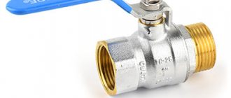
Stopcocks
The shut-off valve consists of a body, a shut-off element, a handle and sealing gaskets. The locking element can be spherical, cylindrical or cone-shaped.
The material used is usually cast iron or steel, but bronze and brass are also found. Valves are divided according to the type of shut-off element (ball or plug) and according to their attachment to the pipe.
The element blocking the movement of the medium in ball valves has a spherical shape with a through hole. The sphere rotates 90 degrees, which allows it to open and close the flow of the medium, as well as take intermediate positions. It is believed that a ball valve is better than plug valves, which only open and close the flow.
Device mounts:
- couplings, which are installed by screwing nuts onto the threads;
- flanged, when the fasteners are flanges connected by bolts;
- intended for welding joints.
Depending on the direction of the flow of the medium, valves are straight-through, angle, three-way or multi-way. The number of pipes will be different.
According to the nature of the movement of the shutter, the taps can be pressed, rotated, with lifting or without lifting the shutter. The control method is either manual, or with hydraulic, pneumatic or electric drive.
Tightness is ensured by the stuffing box or tension method.
- Devices with gland sealing are installed on pipelines that deliver water or oil. Such taps are made of cast iron, and they can operate at temperatures up to 100 degrees Celsius.
- Devices with tension sealing are usually used on gas pipelines, and for normal operation they need: a temperature of up to 50 degrees and a pressure of 0.1 MPa.
Note! Taps made of plastic cannot be used at high temperatures (for example, placed on a pipe with hot water), because the parts are deformed and the seal is broken.
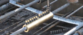
Shut-off valves
The shut-off valve body is connected to the pipe at 2 ends and is equipped with a seat, which is covered by a spool. A spindle (shaft with right and left turns of rotation) passes through the hole in the housing, and with the help of a running nut it sets the spool in motion. When the spool reaches the lowest point, it stops, closing the flow of the medium.
We recommend that you read: Design of a three-way ball valve
Among the shut-off valves, there are models where there is no running nut, and instead of a spindle there is a smooth rod. The force that it transmits from the drive is called translational, and a valve with such a structure is called shut-off. This type of device is controlled by a pneumatic or electromagnetic drive.
And although there are models with locking and regulating functions, usually the device has a “closed” or “open” position, there is no gap, so its main purpose is not to regulate the flow of the working medium, but to block it.
The valve is resistant to mechanical stress and operates over a wide range of temperatures and pressures. The dimensions are compact, the sealing is tight. It is used to work with liquid, gaseous and aggressive media.
Note! The valves operate at any pressure, including deep vacuum. But for high pressure, devices with welded mounts are suitable.
Dampers and gate valves
Valves are suitable for pipes with a large diameter but low pressure, because their tightness is low. The locking element is usually made of steel, and the device body is made of cast iron.
The valve is attached to the pipe either with flanges or by welding, which is controlled manually (flywheel), hydraulically or electrically.
Dampers are used on pipelines of medium or large diameter (up to 2.2 m) in sewer systems or when working with chemical media. Since their tightness is low and the dampers cannot cope with high pressure, they are not used in water supply and heating systems.
Safety valves.
The integrity of the safety valve body may be compromised due to corrosion, fatigue, or increased permissible pressure.
Due to damage to the sealing surfaces or foreign objects on them, misalignment of valve parts and other reasons, it is possible for the pumped liquid to pass through the valve seal at a pressure less than the calculated one.
Due to the excessively high flow rate of the discharged liquid, as well as deposits on the surface of the supply pipeline or pipe, pulsation may occur - rapid and frequent closing and opening of the safety valve.
Finally, the safety valve may simply not operate at a given set pressure due to an incorrectly adjusted or too stiff spring, as well as increased friction in the spool guides.
Therefore, the scope of safety valve maintenance includes:
- external inspection to determine the integrity of the body;
- checking valve operation at a given pressure;
- control of tightness and pulsations.
Maintenance of safety valves is performed by maintenance personnel 2 times per shift.
5.2. RULES FOR TECHNICAL OPERATION OF THERMAL POWER INSTALLATIONS
5.2. Pipelines and fittings
5.2.1. The head of the organization appoints persons responsible for the good condition and safe operation of pipelines from among the engineering and technical workers (heads of workshops and services) who have passed the test of knowledge of the rules for the design and safe operation of steam and hot water pipelines, these Rules and other industry regulatory documentation (instructions, emergency circulars, etc.).
5.2.2. The organization compiles lists of pipelines that are subject to registration with the Gosgortechnadzor of Russia and accounting at the enterprise. The lists indicate the persons responsible for the good condition and safe operation of pipelines. A passport is issued for each pipeline in the prescribed form.
5.2.3. The fittings must be used strictly in accordance with its functional purpose. The use of shut-off valves as control valves is not permitted. Fittings with a nominal diameter of 50 mm or more must have passports of the established form.
5.2.4. The design of pipelines and their operation must exclude the occurrence of additional internal stresses on pipeline elements associated with their thermal elongation or other external forces exceeding the design ones.
5.2.5. After a major overhaul, as well as repairs associated with cutting and re-welding sections of the pipeline, replacing fittings and thermal insulation, the following are checked before putting the equipment into operation:
— serviceability of fixed and movable supports and spring fastenings;
— the tightening size of suspension springs and supports in a cold state;
— serviceability of thermal movement indicators;
— the possibility of free movement of pipelines when they are warmed up;
— condition of drains and vents, safety devices;
— ease of movement of the moving parts of the fittings;
— correspondence of the signaling of the extreme positions of the shut-off valves (“open” - “closed”) on control panels to its actual position;
— serviceability of thermal insulation.
Hydraulic tests are also carried out to check the strength and density of the repaired section with all elements and fittings using test pressure. The test results are entered into the passport.
The fittings and fittings of pipelines must be subjected to hydraulic pressure testing in accordance with the current standard.
The minimum test pressure during hydraulic testing should be 1.25 working pressure, but not less than 0.2 MPa (2 kgf/cm2).
The maximum value of the test pressure is established by strength calculations according to the normative and technical documentation agreed with the State Mining and Technical Supervision Authority of Russia.
The test pressure value is selected by the manufacturer (design organization) within the range between the minimum and maximum values.
5.2.6. The drainage system must ensure complete removal of moisture during heating, cooling and emptying of pipelines, for which the latter must have a horizontal slope of at least 0.004.
5.2.7. When laying drainage lines, the direction of thermal movements must be taken into account to avoid pinching of pipelines.
5.2.8. When drainage lines of several pipelines are combined, shut-off valves are installed on each of them.
5.2.9. The fittings must have inscriptions defining their purpose, be numbered according to the technological diagram of the pipelines, and also have indicators for the direction of rotation of the steering wheels.
5.2.10. Control valves are equipped with indicators of the degree of opening of the regulating body, and shut-off valves are equipped with “open” and “closed” indicators. The fittings must be accessible for maintenance.
5.2.11. Service platforms are installed at the installation sites for fittings and thermal movement indicators of steam pipelines.
5.2.12. Repair of pipelines and fittings is carried out simultaneously with the repair of the corresponding thermal power plant.
5.2.13. Thermal insulation of flange connections, fittings and sections of pipelines subject to periodic inspection (welded joints, etc.) must be removable.
5.2.14. Thermal insulation of pipelines located in the open air, near oil tanks, oil pipelines, fuel oil pipelines, is equipped with a coating to protect it from saturation with moisture or oil products.
5.2.15. For thermal insulation, materials are used that do not cause corrosion of pipeline metal.
Check valves.
Similar to gate valves, maintenance of check valves is performed by maintenance personnel once per shift and includes:
- checking the tightness of seals (with elimination of detected leaks);
- monitoring the performance of damping devices and their restoration;
- cleaning the outer surface.
The tightness of check valves is checked once a year, similar to gate valves. It should correspond to the values given in the table below.
Check valve tightness standards
| Nominal pressure, MPa | Allowable leakage flow rate (cm3/min) at nominal diameter of check valves DN (mm) | |||
| 300-400 | 500-700 | 800-1000 | 1200 | |
| Less than 4 | 25 | 45 | 80 | 150 |
| 4 and above | 12 | 20 | 40 | 80 |
Electric drives.
Reliable operation of the electric drive is ensured by:
- maintaining its components and parts in working order;
- careful fastening of the drive to the valve, the electric motor to the gearbox, and the limit switch to the drive;
- timely operation of limit switches and torque limiting clutch;
- high-quality lubrication of its rubbing parts.
Therefore, during maintenance of the electric drive, a visual check is made of the condition of the electric drive and supply cables, the condition and fastening of the electric motor terminals, checking the protection of the electric motor from overloads, checking the operation of the limit switches and their revision, checking the operation of the torque limiting clutch, as well as checking the presence of lubrication in the bearings and gearbox and its replenishment.
The main malfunctions of electric drives and methods for eliminating them are given in the table below.
Work performed during maintenance and repair of shut-off and control valves.
Maintenance of shut-off valves
Maintenance schedule.
One of the conditions for reliable operation of shut-off and control valves is the organization and mandatory implementation of a system of scheduled preventive maintenance (PPR). The PPR system includes a set of organizational and technical measures for supervision, maintenance and repair of shut-off valves, helping to increase the durability of their operation, prevent accidents on gas pipelines, and improve the operating culture.
The PPR system does not provide for unscheduled work associated with emergency failures caused by unsatisfactory installation or improper operation of shut-off and control valves.
The essence of the maintenance system is that, regardless of the technical condition, a certain type of planned maintenance is carried out - scheduled inspection, routine and major repairs.
A scheduled inspection is a set of repair and maintenance work to monitor the technical condition of cranes, identify emerging defects, and timely prevent the occurrence of malfunctions. During this procedure, only those faults are eliminated that make normal operation of the cranes impossible until the next repair. The list of works and their frequency performed during routine inspection of shut-off and control valves is given in Table 2.
Current repair is a set of works to monitor the technical condition of cranes, identify and eliminate defects that have arisen associated with the disassembly of individual components. The list of works and their frequency performed during routine inspection of shut-off and control valves is given in Table 2.
A major overhaul is a repair performed to restore serviceability and complete or close to full restoration of the equipment life of a product with the replacement or restoration of any of its parts, including basic ones.
For each unit of shut-off and control valves, a passport is issued with records of work performed in accordance with the “Regulations...” and these instructions.
Shut-off and control valves must be replaced only after all necessary measures have been taken to eliminate leaks, restore operability and the corresponding report has been drawn up with the involvement of ITC UZA specialists. Cut-out shut-off valves, except for valves that have served for more than 15 years, must be preserved for subsequent sending for repair to specialized enterprises. Cut-out shut-off valves must not be disassembled, drives or attachments must not be dismantled. to drain technical fluid from the drive hydraulic system .
Before installing new shut-off and control valves, a set of works is carried out on it by specialized organizations with which an agreement has been concluded or by maintenance teams for the LPUMG.
The emergency supply of shut-off and control valves is stored in accordance with the approved lists at the UMTS bases and in the LPUMG.
The shelf life of shut-off and control valves is no more than 5 years from the date of manufacture. Before this period is reached, it must be installed for its intended purpose on the MG. The minimum emergency reserve must be at least 40% of the total quantity of shut-off and control valves.
Storage conditions must ensure the safety of the original packaging, the serviceability of the crane, components and parts.
In addition to the scheduled inspections carried out according to Table 2, shift personnel conduct daily inspections (TO-1), the list of works and frequency of which is indicated in Table 1.
To streamline the work, a maintenance map-1 is drawn up for shift personnel, according to which all process piping valves are assigned to shifts. Any detected defects are recorded in the defect log.
If it is necessary to perform specialized work, specialists from third-party organizations are involved.
After eliminating defects and malfunctions, a corresponding entry is made in the maintenance log.
Table 1.
Scroll
Work performed during maintenance of shut-off valves
| No. | Contents of work | Periodicity | Executor |
| 1. | Checking the completeness of the main components, identifying breakdowns and external malfunctions. | Every shift | Shift staff |
| 2. | Checking control units and detachable connections for gas leaks and eliminating them. | Every shift | Shift staff |
| 3. | Checking the tightness of the valve body along the flanges, welded joints and spindle. | Every shift | Shift staff |
| 4. | Checking the specified position of the hydraulic pump distributor handles, operating mode taps and valves. | Every shift | Shift staff |
| 5. | Inspection of hydraulic cylinders, hydraulic cylinders and oil lines to detect oil leaks and eliminate them. | Every shift | Shift staff |
| 6. | Checking the extreme position of the ball valve (according to the indicator) | Every shift | Shift staff |
| 7. | Inspect check valves and their oil dampers to detect oil and gas leaks, loose fasteners and damaged seals. | Every shift | Shift staff |
Table 2.
SCROLL
work performed during maintenance and repair of shut-off and control valves.
| No. | Contents of work | Periodicity | Executor |
| 1 | 2 | 3 | 4 |
| I Scheduled inspection Ball and conical valves | |||
| 1 | Checking the completeness of the main components, identifying breakdowns and external malfunctions, the presence of all inscriptions and plates | 1 time per month | Specialized teams, operational personnel |
| 2 | External inspection of instrumentation and automation equipment and checking the tightness of connections (impulse lines, control units, limit switches, terminal boxes). | 1 time per month | Specialized teams, operational personnel |
| 3 | Inspection of cylinders, hydraulic cylinders and oil lines to detect hydraulic fluid leaks and eliminate them. | 1 time per month | Specialized teams, operational personnel |
| 4 | Check that the ball valve is correctly installed in its extreme position using a manual oil pump or steering wheel. | Once a month and after each relocation of the tap. | Specialized teams, operational personnel |
| 5 | Checking the specified position of the hydraulic pump distributor handles, operating mode taps and valves. | 1 time per month | Specialized teams, operational personnel |
| 6 | Inspect check valves and their oil shock absorbers to detect hydraulic fluid and gas leaks, loose fasteners and damaged seals. | 1 time per month | Specialized teams, operational personnel |
| 7 | Removing moisture and condensation from the valve body through drainage. | 1 time every 3 months | Specialized teams, operational personnel |
| 8 | Check for freezing of the ball valve to the valve body by partial maneuvering (no more than 10 degrees). | In winter, once a month | Specialized teams, operational personnel |
| 9 | Checking hydraulic fluid levels in cylinders and hydraulic cylinders. | 1 time every 3 months | Specialized teams, operational personnel |
| 10 | Checking the operation of control units by local and remote testing with the pulse gas supply tubes disconnected from the hydraulic cylinders. | Once every 3 months and when the GPU is removed from repair | Specialized teams, operational personnel |
| 11 | Checking the functionality of distributors, hand pumps, spool valves, switches for the type of work. | 1 time every 3 months | Specialized teams, operational personnel |
| 12 | Checking the tightness of the valve body along the flanges, welded joints and spindle. | 1 time per month | Specialized teams, operational personnel |
| 13 | Checking the tightness of the seals of the pistons and rods of the power cylinders. | Once every 6 months | Specialized teams, operational personnel |
| 14 | Checking the open position of the oil flow regulator. | 1 time every 3 months | Specialized teams, operational personnel |
| 15 | Checking the settings of the limit switches. | 1 time every 3 months | Specialized teams, operational personnel |
| 16 | Checking the functionality of the valves of the inlet and outlet valves of UP KS (cranes equipped with a remote control system are checked in conjunction with this system.) | Once every 6 months | Specialized teams, operational personnel |
| 17 | Checking the functionality of the pulse backup system at the LCHMG | Once every 6 months | Specialized teams, operational personnel |
| 18 | Checking the tightness of the valves on the seats: - spark plug valves KS. - the rest of the cranes at the compressor station. | - once every 3 months. -at least once every 6 months. | Specialized teams, operational personnel |
| Wedge valves | |||
| 19 | Checking the completeness of the main components, identifying breakdowns and external malfunctions, the presence of all inscriptions and plates | 1 time per month | Specialized teams, operational personnel |
| 20 | External inspection of instrumentation and automation equipment and checking the tightness of connections | 1 time per month | Specialized teams, operational personnel |
| 21 | Checking the correct installation of the wedge gate in the extreme position using the steering wheel. | Once a month and after each repositioning of the wedge. | Specialized teams, operational personnel |
| 22 | Checking the tightness of the shut-off valve body along the flanges, welded joints, spindle, stuffing box. | 1 time per month | Specialized teams, operational personnel |
| 23 | Checking the settings of the limit switches. | 1 time every 3 months | Specialized teams, operational personnel |
| Maintenance and repair of the electric drive in accordance with the operating instructions for each type of drive. | |||
| Regulator taps | |||
| 24 | Checking the locking of fastening connections and the tightness of threaded connections of pipelines. | 1 time per month | Operations personnel |
| 25 | Checking the functionality of the heating tape (if equipped). | Once a month (except summer) | Operational personnel of ACS, A and TM, GKS services. |
| 26 | Checking the oil level in the oil tank of the control unit and the gas pressure in the piston accumulator. | 1 time per month | Operations personnel |
| 27 | Checking the lubrication of the oil pump motor bearings in the electrohydraulic control unit. | 1 time per year | Operational personnel of ACS, A and TM, GKS services. |
| 28 | Checking the electrical parameters of the oil pump motor. | Once every 6 months | Operational personnel of the ACS, A and TM service |
| Shut-off and control valves in emergency reserve | |||
| 29 | Checking the paintwork of the faucet. | 1 time per year | Responsible persons appointed by order for the enterprise |
| 30 | Checking compliance with technical documentation. | 1 time per year | Responsible persons appointed by order for the enterprise |
| 31 | Checking the presence and level of hydraulic fluid in the drive. | 1 time per year | Responsible persons appointed by order for the enterprise |
| 32 | Checking the conservation lubricant on the inner surface of the valve, the faucet connecting pipes and on all unpainted surfaces. | 1 time per year | Responsible persons appointed by order for the enterprise |
| 33 | Checking the integrity of the plugs of through passages and technological openings. | 1 time per year | Responsible persons appointed by order for the enterprise |
| 34 | Checking the completeness of the main components. | 1 time per year | Responsible persons appointed by order for the enterprise |
| II Current repairs Ball and conical valves | |||
| The scope of work provided for by the scheduled inspection. | According to scheduled inspection | Specialized brigades | |
| 1 | Cleaning areas susceptible to corrosion, priming. Painting the external surfaces of the above-ground part of the crane. | 1 time per year | Specialized brigades |
| 2 | Tightening of all threaded connections of drives, hydraulic cylinders, extension columns and attachments. | Based on the inspection results | Specialized brigades |
| 3 | Cleaning filter driers and replacing the adsorbent with its subsequent regeneration. | Depending on the humidity of the gas, but at least once a year. | Specialized brigades |
| 4 | Adding hydraulic fluid to check valve dampers. | Based on the inspection results | Specialized brigades |
| 5 | Refilling hydraulic fluid into valve cylinders. | Based on the inspection results | Specialized brigades |
| 6 | Removing air from hydraulic cylinders of cranes. | Based on the results of the inspection. | Specialized brigades |
| 7 | Adjustment of the extreme position of the ball valve. | Based on the inspection results | Specialized brigades |
| 8 | Opening check valves, cleaning the internal cavity and inspecting all components, during which the locking of the shafts (half shafts) of the brackets and the smooth movement of the shutter are checked | During planned shop shutdowns. | Specialized brigades |
| 9 | Inspection of the hydraulic system, removal of moisture and sludge. | 1 time per year | Specialized brigades |
| 10 | Inspection and lubrication of the actuator. | 1 time per year | Specialized brigades |
| 11 | Inspection and repair of instrumentation and automation equipment. Measurement of insulation and grounding resistance | 1 time per year | Specialized brigades |
| Packing valve seals with greases | |||
| 12 | - taps with a metal-to-metal seal (with multipliers) and plug valves; - hermetic taps with soft seals. | Before each change and after closing. Once a quarter. | Specialized brigades |
| Filling the tap with sealing pastes: | |||
| 13 | - taps are leaky. | Based on the results of a routine inspection and after closing the tap | Specialized brigades |
| 14 | Complete replacement of hydraulic fluid in the drive. | According to those passports for hydraulic fluid | Specialized brigades |
| Wedge valves | |||
| 15 | Tightening of all threaded connections of drives. | Based on the inspection results | Specialized brigades |
| Regulator taps | |||
| 16 | Cleaning filter driers and replacing the adsorbent, removing moisture and solid particles from the condensation separator. | Periodically, depending on the humidity of the gas, but at least once a year. | Operations personnel |
| 17 | Tightening of all threaded connections. | Based on the inspection results | Operations personnel |
| 18 | Adding oil to the oil tank of the control unit, recharging the piston accumulator with inert gas. | Based on the inspection results | Operations personnel |
| 19 | Adjustment of gas pressure measurement channels P1 (gas inlet to the regulator, if available), P2 (gas outlet from the regulator). | At least once every 6 months | ACS, A and TM specialists |
| 20 | Recharging the built-in battery in the electronic control unit during long-term storage or a long break in operation. | According to the technical data sheet. | ACS, A and TM specialists |
| 21 | Setting up the software of the control valve control unit, diagnostics of the actuator and the regulating body of the control valve. Configuring EPT limit switches on DKD | 1 time per year | Specialists in automation, automated control systems, automation and technical equipment |
| 22 | Checking the lubrication of the oil pump motor bearings in the electrohydraulic control unit. | 1 time per year | Operational personnel of ACS, A and TM, GKS services. |
| 23 | Checking the electrical parameters of the oil pump motor. | 1 time per year | Operating personnel of the ES service |
| Shut-off and control valves in storage | |||
| 24 | Re-preservation of the air defense system. | Once every 30 months | Operational services responsible for storage. |
The inspection results, detected malfunctions and methods for eliminating them must be reflected in the passport for the shut-off and control valves signed by the responsible persons.
Based on the results of routine maintenance, a defect list is drawn up, which is the main technical document for carrying out repairs.
The defect list indicates the scope of the proposed work, the need for materials and spare parts, the necessary mechanisms, lifting vehicles and accessories, and a list of works that can be performed during planned shutdowns is compiled.
Table 3.