Pipeline valves are a type of shut-off valve used to shut off the water supply system or part of it by stopping the supply of the transported liquid. The mechanisms are designed to distribute water flows in the required directions, regulate pressure, and control resource consumption by changing the diameter of the passage.
Types of valves for pipelines.
Varieties of wedge design
The operating principle of wedge valves also depends on the type of valve.
It can be produced in the form of:
- A rigid plate tapering towards the bottom. In this case, the wedge is a single piece, the principle of which is to smoothly lower into the lower part of the body, while being perpendicular to the axis of the pipeline. The wedge fits tightly to the two side saddles and interrupts the movement of the working substance. This design has a number of disadvantages, among them are:
1. danger of jamming; 2. difficulties in lifting the wedge as a result of sudden changes in temperature of the working substance; 3. difficult fit to saddles. - A double-disk wedge consisting of two elements movably fastened together at an angle to each other. A double-disc wedge valve is a more advanced design than a rigid wedge. Its operating principle is as follows: when the valve is closed, the disks rotate relative to each other and are pressed tightly against the seats; when opened, the disks move away from the seats and clear the holes for the passage of the working substance. It provides high tightness of the locking organ, reduces the risk of jamming, requires less force to close. Its sealing surfaces are less subject to wear.
- Elastic locking organ. Structurally similar to a double-disk wedge, with one difference - its disks are connected to each other using an elastic element. The advantages of its operating principle are the ability to bend under the pressure of the working medium and provide a tighter relationship with the planes of the sealing material when closing the valve. Closing devices with a rubberized wedge They have low operating torque and a smooth full passage, so there is no strong friction and high wear on the locking elements.
Characteristics and requirements
- Gate valves must comply with the requirements of GOST 5762, TU and KD.
- Nominal sizes from DN50 to DN1600 inclusive.
- Nominal pressures from PN1.6MPa(PN16) to PN25MPa(PN250) inclusive.
- The design of valves intended to operate in vacuum must ensure their tightness relative to the external environment and the valve at a pressure of up to 0.004 MPa.
- In valves intended for operation on pipelines in which heating of condensate located in a closed volume of the body is possible, a device must be provided to prevent the pressure in them from increasing above the permissible value.
- Gate valves with a nominal diameter up to DN150 inclusive must have a wedge of a rigid structure, over DN150 to DN300 inclusive - a wedge of a rigid or elastic structure, over DN300 - an elastic structure.
- Connection of valves to the pipeline: flanged according to GOST 12815, counter flanges according to GOST 12821.
- Valves are tested in accordance with RD 26-07-263-86.
- The design of the valve bodies is full bore.
The material of the sealing surfaces of the valve assembly parts must be wear-resistant, ensuring the life-time reliability of the valves. The corrosion rate of the material of the sealing surfaces of the valve assembly parts is no more than 0.05 mm/year. If the material of the body seats and parts of the valve assembly in contact with them does not provide the specified corrosion rate and the required wear resistance, then the standards (TU, KD) for specific valves provide for surfacing the sealing surfaces with corrosion-resistant wear-resistant alloys.
Gate valve seats can be made in accordance with the standards (TU, KD) for specific gate valves, either together with the body or plug-in (with threaded fastening, pressing, welding and other methods).
By the way, read this article too: Stop valve (valve)
Tightening of threaded connections of valves is carried out with a standard tool or specified in the technical documentation for a specific valve with a special tool without the use of extensions. Structurally, ensure that the ends of bolts and studs protrude from the nuts by at least one thread pitch.
The cuts of adjacent rings of the stuffing box are shifted during assembly by an angle of 90° ± 5°.
The design of the valve must ensure that the simultaneous operation of the drive and handwheel is blocked.
Scope of application and benefits
Wastewater treatment: types and principle of operation
Pipeline valves are produced in a diameter range from 15 to 2000 mm. They are intended for installation in systems with a working environment temperature of up to 550 degrees and pressure of up to 25 MPa inclusive. The scope of use of the valve directly depends on the material from which its body is made. The most common steel structures can be used:
- in the field of housing and communal services for installation on central water supply and heating pipelines;
- in the oil and gas and energy industries on transport routes;
- in production areas on pipelines supplying vaporous, liquid and bulk substances.
Valves are also produced in stainless steel bodies, due to the resistance to corrosion of which they are widely used in the chemical and pharmaceutical industries.
The design features of the valve do not allow it to be used as a control valve; the shut-off element must always be in the extreme positions - “closed” or “open”, otherwise the wear of the sealing surfaces and, as a consequence, the working life of the structure will be significantly accelerated.
Flanged rising stem valves offer the following performance advantages:
- simplicity of layout, reliability and maintainability;
- minimal hydraulic resistance;
- small overall length;
- possibility of equipping with mechanized drives of hydraulic, electric or pneumatic type;
- ease of installation and the ability to quickly dismantle due to the flange connection.
Gate valve height
The design also has disadvantages, the main one being the large overall height due to the spindle, the length of which is identical to the diameter of the through hole in the body. When the valve is opened, the spindle comes completely out of the body, which requires free space above the pipeline.
A valve with a non-retractable spindle differs from the design we are considering in that its spindle, when opening the valve, performs exclusively rotational movement, while the retractable rod moves rotationally and translationally. Compared to fixed fittings, the retractable spindle design requires significantly less opening time.
The disadvantages of valves also include fairly rapid wear of the sealing surfaces on the seats and the valve due to their constant friction, which requires frequent scheduled repairs, which cannot be performed without installing the valves from the pipeline.
Operating principle and design features
In most cases, valves are made in a full bore configuration, which provides the same cross-section of the body opening in relation to the diameter of the pipeline on which the valves are installed.
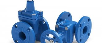
Double-disc wedge gate valve
The design of a wedge valve consists of the following elements:
- Housing (steel, cast iron or stainless steel).
- Wedge-shaped locking mechanism.
- Two saddles into which the shutter rests when closing the passage hole.
- Drive of manual or mechanical type.
- The spindle is fixed with a running nut that guides its movement inside the housing.
When the drive is activated, the rod, rotating around its axis inside the running nut, moves to the bottom and moves the locking mechanism, which closes the passage hole. Sealing of the cutting off of the working medium is achieved by covering the valve and seats with elastic material. Depending on the type of coating, several types of fittings are distinguished; the most common are valves with a rubber-coated wedge and structures with a valve coated with fluoroplastic.
The lower part of the valve body is all-welded; a cover is attached to it with screws, from which the spindle emerges. On the side parts of the housing there are connecting pipes equipped with flanges. The flange is a round steel plate, along the perimeter of which there are mounting holes for mounting screws.
When installing the fittings, a counter flange is welded onto the pipeline, having similar dimensions and pitch between the screws as the valve flange. A sealing gasket made of rubber or paronite is placed between the plates and the flanges are fastened together with fasteners. The sealing gasket ensures maximum tightness of the connection.
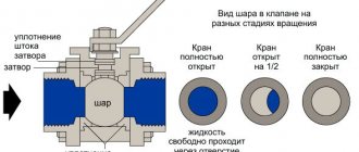
What is it and where are they used?
Gate valves are a common type of shut-off valves used to completely block the movement of the medium for carrying out repair work in the system or maintenance of plumbing fixtures. They are equipped with almost any pipelines with a diameter from 15 mm to 2 m in hot/cold water and oil products supply systems operating with constant high-speed movement of the medium under pressure up to 25 MPa. They have a relatively simple design, short overall length, low hydraulic resistance, are suitable for operation in conditions of varying complexity, and can be controlled manually or using an electric drive.
To shut off gas equipment, Ludlo type valves with a retractable spindle are most often installed.
If valves are mainly used as shut-off devices, then water stops perform both functions of pipeline fittings. They have the ability not only to stop the flow, but also to regulate the flow of water. However, they are limited in terms of the permissible operating pressure - up to 2.5 MPa.
Wedge valves features
Shut-off valves for pipelines types classification
The main advantage of a wedge device for blocking the flow of liquid in a water pipe is the location of the seats at a slight slope. Thus, the movable element takes the form of a rigid, double-disc or elastic wedge. In any case, when closed, the wedge fits tightly between the seats, ensuring absolute tightness of the system. The type of locking element is selected depending on the application.
A wedge, consisting of two disks, does not require maximum precision in manufacturing (unlike a rigid element), while still providing sufficient tightness. The main disadvantage of such an element is its more complex design, which affects the cost of the finished product.
The elastic wedge combines the advantages of the first two types: simplicity of design and ensuring tightness in case of inaccuracy in the selection of the device.
The main advantage of a parallel device (in comparison with a wedge device) is the simplicity of the design (parts located in parallel are much easier to manufacture, which means the likelihood of error and error is minimal).
Parallel plumbing fixtures can be either with a retractable or non-retractable spindle. The first option is more durable, since the threaded connection does not come into contact with the moving medium, the second is more compact.
The diameter of the passage hole and the length of the device may vary, so you can always choose the best option for your system.
Ludlo Gate Valve
The Ludlo valve is a parallel, double-disc spacer wedge valve that has been in common use throughout the world for over 150 years. The name of the device comes from the name of the company that first put it on the market - Ludlow Valve Manufacturing Company.
Such devices are made exclusively from cast iron and are extremely durable (more than 100 years). In our country, production has been established since the 80s of the last century in St. Petersburg.
The main advantage of such a system is the elimination of contact of steel parts with the moving medium, which has a positive effect on the durability of the device. The main thing when choosing hose fittings is to choose the right brand of rubber. The choice depends on the application; most often, such devices are used on pipes through which aggressive and viscous liquids move.
The design of a gate valve is almost identical to a parallel one. The only difference is the use of one gate instead of two saddles to shut off the pipe. This device is the least reliable of all presented, therefore it is used only in systems that do not require absolute tightness (for example, sewage and other systems with a large amount of impurities).
Operational performance indicators
Regardless of the valve models, general performance indicators have been established. These include:
- bore diameter du - the indicator varies from 50mm to 1200mm;
- nominal pressure pn – from 10 to 40 atmospheres (1.0-4.0 MPa);
- seal tightness class - A, AA, B, C, established in accordance with the provisions of GOST 9544-2015;
- type of connection to the pipe - welding or flange connection, made in accordance with GOST 33259-2015;
- ambient temperature indicators in accordance with the climatic design, which is determined according to GOST 15150-69;
- lower and upper limits of the working environment temperature depending on the climatic version;
- medium supply direction
- drive type – manual, mechanical or electric drive (adapter installation dimensions according to OST 26-07-763-73).
The selection of a valve for a specific working environment is based on the resistance of the material of the body parts to corrosion damage. In accordance with GOST 9.908-85, the corrosion rate cannot exceed 1 mm per year.
The climatic design of steel and cast iron valves according to GOST 15150 is different. So for steel products the following versions are used:
- T1 – operation at temperatures ranging from -100C to +500C;
- ТпУ1 – from -290С to +400С;
- U1 – from -400С to +400С;
- HL1 – from -600С to +400С.
Cast iron products are also classified according to GOST 15150, but with other markings (U, T, UHL, OM).
Automatic mode circuit
Septic tank Rostock: principle of operation, design and installation
The automatic valve control scheme occurs without operator intervention in the process. To enable this mode, move switch 1PU to the “Automatic” position. You also need to move the VK toggle switch to the on position. Switch 1VB must be turned off, and switch 2VB must be turned on.
The command is issued depending on the parameter values by closing contacts 1РК or 2РК. The signal turns on the 1RP or 2RP relay. After this, the magnetic starters receive the appropriate command. They perform either full opening or full closing of the valve. The commands are controlled by the lighting of the LO, LZ lamps.
The circuit includes a torque correction switch. Light indication is used to indicate the action. Some models have a thermal switch to protect against overheating. They are additionally equipped with an automatic reset system. It must be connected to maintain the hardware warranty.
type of drive
According to GOST 5762-2002, the valves produced are manufactured for pipelines with a bore diameter from 15 to 1600 mm. Devices with a nominal diameter of 50 to 800 mm are in demand in production.
This variation in standard sizes causes a large difference in the dimensions of each model. For example, the weight of a valve with a passage diameter of DN 50 is no more than 40 kg. But the 800 mm model weighs about 3.5 tons. Accordingly, it is inconvenient to use such a device with a manual mechanism.
Therefore, manufacturers complete valves with different drives.
There are:
- manual;
- mechanical;
- electrical;
- electromagnetic;
- pneumatic;
- hydraulically driven.
Visually, the hydraulic drive is similar to a pneumatic drive. They differ only in the control medium: the first uses liquid, the second, respectively, gas (air).
The control medium is the way the gate is influenced. In our case, it is a liquid or gas.
The most popular drives are manual, mechanical gear and electric.
Marking of models equipped with a mechanical gearbox: 30s564nzh, 30s527nzh. The number “5” indicates the type of drive – gearbox.
Models on which an electric drive is installed are marked with the number “9”. For example: 30s964nzh, 30s941nzh.
Cast iron fittings are marked in a similar way. Example: 30h906br.
Electric drives are also installed on small diameter valves. This is due to the length of the pipeline systems. In this case, the highway is divided into sections controlled by a single remote control.
When installing an electric drive, you must be guided by the type of drive connection specified in GOST R 55510-2013. The product data sheet indicates the maximum torque. It is individual for each model. Failure to comply with these requirements may result in damage to the wedge or leakage of the operating fluid into the atmosphere.
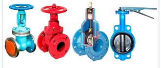
Kinds
According to their design, the devices are divided into:
- wedge;
- parallel type;
- gate
In parallel cast iron flanged valves, the sealing surfaces of the seat elements are arranged in parallel. The shutter mechanism contains 2 discs. To achieve a closed state, the elements are pulled to the seats using a special wedge, stopping the passage of the chemical or gas composition.
In wedge valves, the seats inside the body are located at an angle. The valve element is made in the form of a wedge of a dense composition or consists of 2 disks. Cast iron valves with a rubber wedge are used in structures that require high tightness, because securely secure the valve in the closed position.
The gate valve is similar in shape to the parallel device, but is equipped with 1 locking disc. The design solution is optimal in pipelines with one-way flow of media that do not require high tightness parameters of the shut-off element. The unit is installed in pipeline systems that transport sewage water, pulp, sludge, water with impurities, etc.
The permissible pressure in products can be:
- high;
- average;
- low.
Devices operating under low pressure are equipped with a flat-shaped housing.
Models operating under medium pressure have an oval shape.
Products operating under high pressure are equipped with a spherical body.
According to the diameter, the device can be:
- full bore;
- narrowed.
The reduced hydraulic resistance of the full-bore device is ensured by precise adjustment of the diameters of the pipe and valve.
The narrowed device has a diameter smaller than the pipeline opening. The design solution helps to increase hydraulic stress, while reducing wear of the seals.
Based on the control method, systems are distinguished:
- manual type;
- with electric drive.
Manual valves are activated by a handwheel. The devices are used in systems with small diameters (up to 150 mm).
Electrically driven locking devices are universal, but are most often used in large-sized systems located in hard-to-reach places. The mechanism optimizes operation by allowing the valve to be closed and opened remotely.
The nodal mechanism of the valve is designed:
- with retractable spindle;
- with a non-retractable spindle.
The retractable spindle helps reduce the impact of acid-liquor compounds on the internal elements of the locking device. The design solution ensures easy dismantling and repair of the product. The running nut and thread are applied to the outer surface of the housing.
The non-retractable spindle is constantly in an acid-base or gas environment. The element is subject to processes of oxidation, corrosion, and deformation from abrasive particles. In working condition, access to the element is impossible. Operating conditions lead to rapid wear of the product; regular replacement of node connections is required.
Installation rules
When installing a valve into a pipeline, the worker must:
- comply with the rules for carrying out relevant work at the enterprise;
- norms and rules of labor protection;
- have protective clothing and equipment (PPE);
- pass certification;
- have experience in installing shut-off valves.
The procedure for training enterprise employees in labor safety rules is set out in GOST R 53672-2009.
The product must be in its original packaging until it is installed. Immediately before installation, the valve must be checked for functionality by performing 3 cycles of operation of the valve. A visual inspection of the external and internal parts of the housing is also carried out.
Before installation, the spindle (thread) must be lubricated with VNII NP-232 paste, regulated according to GOST 14068.
The product can only be hung by the connecting pipes.
Figure 10. Slinging
Work order.
- Shut off and relieve pressure in the pipeline.
- Flush the system with water.
- Clean the installation site from foreign objects and dirt.
- Sling the product according to the diagram attached to the instruction manual.
- Carefully, avoiding hitting the pipeline, bring the valve to the connecting flanges.
- Insert studs into all flange holes provided by the design.
- Screw the nuts onto the studs.
- Tighten the nuts with a special wrench.
- The slings can be removed only after the fittings on the pipeline are fully tightened.
Products with large diameters have a large mass. For example, 30ch539r Ru16 Du1000 weighs about 1.5 tons. Therefore, when installing such a “giant” into the highway, a support is provided. Installation supported by a pipe is strictly prohibited.
Pipeline connection and installation
There are several ways to connect valves to a pipeline:
- Using a flange connection - a special rim on the edge of the locking mechanism, equipped with holes for bolts along the entire perimeter. The same rim is created on the pipe, and the connection occurs by tightening the flanges with bolts and nuts. A flange type connection is used on large diameters where a cast iron or steel pipe system is used.
- On polyethylene and PVC pipes, a coupling connection is used, which is realized by inserting the system elements into the edges of the product body with a lip seal to ensure complete sealing.
- The socket connection is used in PVC and polyethylene systems; the pipes are inserted into the valve sockets, and a lip seal gasket is installed as a sealant.
- The most reliable is a welded connection; in addition, it allows the installation of valves directly on pipes without additional connecting parts.
During installation, it is necessary to take into account several main rules: the locking mechanism must not be installed with the flywheels facing down, the joints must be thoroughly cleaned of dirt, oil, and rust; in the flange connection, the parts must be fixed without distortion.
Installation of valves on metal water pipes
If you need to install a locking mechanism on a metal pipe, the algorithm of actions looks like this:
- A section of pipe is cut out that will correspond to the dimensions of the part being installed, the ends of the cuts are carefully cleaned and polished.
- Further manipulations depend on the choice of connection - either a thread is cut or flange connectors are welded.
- In the first case, sealing occurs with the help of sealing threads, in the second - with O-rings.
- Then the valve is installed in the right place, with a threaded connection it is screwed into the prepared thread, and if the joint is equipped with a flange, both halves are aligned relative to each other, the holes are aligned, and then the bolts are inserted and the flange washer is screwed until completely compressed.
Installation of valves on plastic pipes
When installing on plastic pipes, the plastic welding method is used. They pre-prepare the area for installing the shut-off valves and simply fix them on the pipeline; no seals or additional manipulations are needed.
Installation of valves on chimneys
The valve is installed on the chimney during the installation of the chimney. First, when laying the brick, you need to leave a hole corresponding to the size of the reinforcement, which is then fixed with cement mortar.
Installation recommendations and useful tips
To maximize the service life, you need to correctly select the necessary locking mechanism, the technical requirements that are put forward for them, take into account whether it is a water or gas system, etc.
If control by mechanical rotation is not possible, it is necessary to provide an electric drive with sufficiently sized remote control diameters. Electrically operated valves should be protected from power surges, because After a breakdown, repair of such elements is impossible.
You should not overlook the need to carefully study the installation and operating instructions, since the quality of installation directly affects the service life of the product. If you are not confident in the success of self-installation, it is better to turn to specialists. Especially if it is a steel valve with a retractable spindle (its use is recommended when pumping abrasive substances) or any mechanism on a gas system.
Some installation recommendations and useful tips
There are a number of rules that must be followed during installation, namely:
- Shut-off valves should not, at the time of installation and upon completion of installation, experience external loads, including those from the pipeline;
- the installation site must be accessible for further inspection and maintenance;
- when installing on a horizontal section of the pipeline, it is prohibited to place the device with the flywheel down; on a vertical section, the position of the flywheel can be any;
- Do not disassemble the device under pressure;
- before installing the valve, steam the internal surfaces with hot water followed by drying;
- It is advisable to place a magnetic resonance filter in front of the valve;
- when opening and closing the valve, the steering wheel should be turned smoothly, avoiding jerking;
- tighten the oil seal bushing in a timely manner;
- Pressure testing of the pipeline should be carried out with the valves open.
If you have any useful tips for installing water valves, please share them in the comments. Subscribe to our channel, share your experience with us, as well as on social networks.
(
1 ratings, average: 5.00 out of 5)
Flange valve devices
Despite their simplicity, flanged wedge gate valves are highly effective among shut-off valves. Depending on the locking element, the type of wedge valve is determined. The flanged valve got its name because of its design: on its sides there are flanged disks that mate with the same disks on the pipe.
For flanges on the valve and on the pipe, the diameter and holes must strictly match, otherwise they cannot be connected. A gasket made of paronite, rubber or a rubber ring must be installed between the flanges, depending on the environment inside the pipe
This design of the wedge valve makes it quick-removable, which is important during repairs.
According to the design of the nut, wedge products are divided into 2 categories: with a retractable and fixed nut.
That is, in the first option, when opening or closing the valve, the nut moves progressively. In the second option, the nut remains in place and the screw moves out. In the second category, wedge valves take up less space and are used for the movement of petroleum products and other liquids that do not cause metal corrosion. Wedge products with a sliding nut are mainly used.
According to the closing method, devices are divided into valves:
- With manual control. Closing is done manually using a handle or valve;
- With automated control. With this type of closing, mainly electric motors with gearboxes are used, and they are turned on via a remote control by the operator. Hydraulic and pneumatic drives are used less frequently, due to the additional supply of pipes, instruments, etc.
Application area
The gate valve refers to the shut-off valve. It is used to completely block the flow of the working medium in the pipe.
In the operating technology of various enterprises that have pipeline systems on their balance sheets, there are processes that cannot be carried out without the use of a valve.
Here are the industries in which valves are used:
- city utility networks;
- oil and gas industry;
- shipbuilding;
- food and construction industry.
Almost any manufacturing and operating plant that has the smallest pipeline network needs shut-off valves. The valve is its most common representative.
Operating principle
Regardless of the type, all devices for shutting off a water pipe consist of the following parts:
- Housing with lid.
The housing contains a cavity in which the locking elements are located. In most cases, the body is made of cast iron or steel; the connection with other elements of the engineering system occurs using flanges or by welding. – the ability to quickly and easily replace an element in case of breakdown. A welding seam is the most reliable method of connection, so it is most often used in water supply systems.
- Locking unit.
The locking assembly includes a guide and a shutter. Most often, the guide is part of the body, which ensures maximum reliability of this device and accuracy of all movements. All parts are made of high-quality steel, and the shutter is additionally coated with a layer of special coating that prevents the formation of corrosion.
- Control element.
The control unit consists of a screw rod (valve), a flywheel and a threaded bushing, with the help of which the torque is converted into translational movement of the valve. The unit is installed in the upper part of the device, and all its elements are located in their own metal casing. The connection to the main body occurs using flanges.
includes yoke valve assembly
The pipeline valve operates according to the following principle:
- The operator or electric drive drives the flywheel.
- Thanks to the threaded connection, the rod is driven.
- The rod moves the shutter (this process is controlled by the guide).
- The valve covers the housing, preventing the movement of the liquid medium in the pipeline.
To open the shutter, you must turn the handwheel in the opposite direction.
In most cases, severely worn water shut-off devices cannot be repaired; the only correct solution is replacement. Therefore, carefully monitor its correct use.
Water supply valves
A shutter is one of the modifications of locking devices in which the control element is made in the shape of a disk. The valve attached to the shaft rotates, lowers into the seat and blocks the movement of water. The valve in its operating position is at an angle or perpendicular to the transported liquid.
The mechanism body has a truncated cylindrical shape. The casing is made of cast iron, steel, polymers and non-ferrous alloys. The design of the valve includes a shut-off element consisting of a biconvex metal valve and a rubber sealing ring. Disk devices are operated manually using a handle and automatically using an electric drive. When operated manually, the shutter with the disk is adjusted by turning the lever 90°, which is secured with a nut to the mechanism rod.
Disc rotating devices can be used in water supply, heating systems and for connecting plumbing fixtures.
Butterfly valve for pipeline.
Gate valves, in comparison with gate valves, are short in length, light in weight and have a limited number of working parts. The mechanism body is made of material with a protective coating that is resistant to abrasive inclusions that may be present in the working environment.
Gate valve operation
Gate valves have the ability to pass large volumes of working materials, as well as carry out filtration, grinding of impurities passing through them and dosing useful components.
Based on these capabilities and the peculiarities of the operating principle of the units included in their design, the products are widely used in sewerage drainage systems, in process pipelines of chemical, oil and gas production, construction, pulp and paper, and mining industries.
Gate valves of the ZMS type are used to shut off pressure lines in fountain, wellhead and injection type equipment, and manifolds of drilling rigs.
Attention! Gate valves are always installed in a vertical position, so that the knife plates are perpendicular to the flow of work. . Design and principle of operation of gate-type fittings
Design and principle of operation of gate-type fittings
A metal gate is a plate or a sharp polished and sharpened plate shaped like a knife or guillotine. Its sharp ends are equipped with strong seals (metal or synthetic), which increase the wear resistance of the main working part, especially when operating in aggressive environments with a large number of large granules and impurities.
In the production of seals, synthetic materials are used that are resistant to chemical influences and temperature changes:
- nitrile rubber;
- ethylene propylene diene rubber;
- elastomers for hot environments;
- silicone rubber.
Gate valves have a simple and at the same time reliable operating principle.
It consists of transferring force from the action of a manual, automated or mechanical control mechanism to a rod or spindle, which in turn drives the gate element to completely or partially block the passage hole.
The operating principle of a gate valve is clearly shown in the video.
In this case, the spindle can have a retractable or non-retractable design. The tightness of the retractable rod is ensured by a seal made of synthetic cotton fibers, graphite, etc.
Gate valve selection criteria
To correctly select shut-off valves, you need to know the full characteristics of the system:
- Type and properties of the pumped liquid.
- The nature of the devices' operation.
- The magnitude of hydraulic loads.
- Temperature regime.
- Acceptable dimensions.
- Mechanism weight.
- Drive control method.
- Optimal response speed.
- Tightness.
- Chemical activity of the liquid, material of the body and sealing parts (corrosion resistance).
- Availability of an emergency system with an additional energy source.
- Life time.
When selecting parameters, it is necessary to take into account the maintainability of the equipment, as well as the possibility of its further modernization and automation.
One of the determining factors influencing the choice of valves is their efficiency. The choice of fittings must be made taking into account the price of the device, the cost of its maintenance, as well as the feasibility of the purchase in terms of the economic indicators of the entire pipeline.
Operating principle and device
The presented equipment operates in different working environments (water, steam, oil, etc.). When choosing a particular unit, you need to take into account the environment for which a particular mechanism is designed. Some models of electric drives for valves drive the structure into two positions (open or closed). But there are units designed to work in intermediate positions. The range of positions of their plugs is wider.
The product has a body and flanges. The connection can be parallel or at an angle. Additional sealing is provided by seals.
The valves are equipped with an asynchronous electric motor (ASM) with a squirrel-cage rotor. The motor is coupled to a worm gearbox. The electric drive includes a VP-700 switch, as well as a manual override.
The mechanism is equipped with a rotary disk. It supplies or shuts off the supply of internal media (steam, water, oil, etc.). The control unit and sensors are responsible for this. The locking mechanism moves only after receiving the appropriate signal.
The movement of the plug is ensured by a rod or spindle. The part forms a threaded pair together with the nut. If the spindle does not stick out, this equipment is not installed at a critical facility. The running mechanism is located inside, which complicates its repair and maintenance.
The mechanism is triggered due to changes in temperature, pressure or fluid flow of the pipeline. The signal for moving the plug can be the state of pumps and fans.
Transportation and storage
Before the valve goes on sale, it undergoes final inspection with an inspector’s mark in the product passport (QC). After this, the device is subject to preservation in compliance with the requirements set out in GOST 9.014-78.
Protection options used:
- VU-1;
- VU-0.
Transportation of the product to the place of permanent storage or installation is carried out strictly in the original packaging. In this case, the requirements for transportation and storage set out in GOST 15150-69, paragraph G1 must be met. For transportation of valves with electric drive, the requirements of paragraph G2 are met.
During transportation, boxes with products must be secured in transport containers (railway car, road train body, etc.). During unloading on the territory of the enterprise, you must not throw or tilt (turn over) containers with a valve.
If the product is subject to long-term storage, then all necessary conservation measures specified in GOST 9.014 are carried out.
The valve must be stored in its original box, or, if it is missing, in a clean container of similar dimensions and material of manufacture. In this case, the wedge should be lowered to the lower “closed” position, and the connecting pipes should be closed with plugs.
Figure 9. Container
This procedure will ensure safe storage of the valve for a long time. Additionally, the product is lubricated every six months.
Products with a collapsible body
Hawle E2 wedge valves with an elastic rubber-coated wedge in a collapsible version are produced in short and long versions, equipped with a device for draining water.
Thanks to the design features, the product of this modification allows for preventive cleaning of the system, is capable of withstanding long-term operation at maximum medium pressure and is fully compatible with various pipe sizes and types of electric drives.
The standard configuration consists of:
- Housings with a lid, made of malleable cast iron. All surfaces, externally and internally, are protected from corrosive processes by a layer of epoxy polymer.
- Spindle made of stainless steel with threads of increased length at the ends.
- The locking part is wedge-shaped, cast from cast iron of the same grade, on both sides of which there are separate cuffs made of vulcanized rubber. The product is also equipped with a device for draining (emptying) water.
- Wedge guides are in the form of vertically arranged cylinders with grooves, made of wear-resistant plastic. Their optimal design shape allows for centering of the wedge when closing and opening.
- Cage nut made of brass with a long threaded part, allowing cast iron valves with a rubber-coated wedge to function without failure when the rod is exposed to maximum torsional forces.
- Bushings with stuffing box seals.
- Internal rubber cuff made of elastic polymer suitable for dispensing water intended for drinking.
- Cover bolts. They are protected from corrosion by a special filling suspension and a rubber seal at the junction of the body and the lid.
- Protective ring made of polyacetal ROM. Serves as protection against damage to the anti-corrosion coating during transportation and supports the spindle from dirt.
- Bearing or friction washer (depending on the nominal diameter).
- Groove and centering ring.
Types of connection to the process of valves with a rubber wedge have been developed in several options. The main versions and their features are presented in Table 2.
table 2
| Order number | Series No. | Connecting elements | Peculiarities |
| 1 | 4000 E2, 4700 E2, 4010 E2, 4710 E2 | Flanges | Produced in long and short versions. Closing is carried out clockwise or in the opposite direction. |
| 2 | 4150 E2 | Connecting flanges of different diameters (transition) | They can simultaneously function as a locking mechanism and as an adapter, helping to save building materials, as well as free space at connection points and branches where the installation of adapters is necessary. |
| 3 | 4100 E2, 4140 E2 | Smooth pipes | The main advantage is the optimal placement of the wedge plate guides, designed to reduce friction, wear and closing forces. |
| 4 | 4500 E2 | Bell-shaped | An elastic polymer suitable for the supply of drinking water is used to seal the socket. Replacement of O-shaped seals is carried out in accordance with the standards: up to DN 200 - under pressure; from DN 250 – without pressure |
| 5 | 4027 E2 | Flare and plain pipe (waferless) | The length of the product is adjusted by cutting the pipes. |
| 6 | 4050 E2, 4051 E2 | Sealed and rolled polyethylene pipes | Their high degree of sealing is due to the fact that they are equipped with 2 independent elastomer sealing washers and a support sleeve. When replacing seals, you do not need to reduce the pressure level in the system. |
| 7 | 4090 E2, 4091 E2 | Flange and polyethylene pipe | Designed for engineering systems made of PE pipes. The oil seals are replaced without releasing pressure. |
| 8 | 4040 E2 | Connections for polyethylene (PE 90/100) and polyvinyl chloride pipes | To seal joints with pipes, sealing collars are used; fixation is performed by tightening the clamping ring. |
| 9 | 4041 E2 | Flange and pipe for PE and PVC pipes | Sealing of joints with pipes is carried out using sealing collars |
Prices for collapsible wedge valves at Santekhkomplekt LLC are slightly higher than for solid devices. So, for example, a flanged valve in the short version Hawle E2 DN100 RU16 wedge costs $265, Hawle E2 DN150 RU16 – $370; in the long version the price of Hawle E2 du100 ru16 wedge is already $315
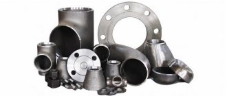
Manufacturing materials
For comparison, let’s look at 2 popular valve brands 30s41nzh and 30ch39r.
Steel valves
The 30s41nzh case is made of steel, as indicated by the letter “c” in the marking. The prefix “NZh” at the end means that the sealing surfaces of the wedge discs and body seats are made of stainless steel.
Figure 4. Shutter 30s41nzh
But what grades of steel are the remaining parts made from:
- The lid and body 30s41nzh are cast from 25L. The letter “L” in the brand indicates that it is cast steel, and the numerical value “25” indicates the content of 0.25% carbon in the alloy.
- The spindle is made of 20X13. This steel contains 14% chromium, which makes it possible to classify this alloy as corrosion-resistant (stainless steel). 20X13 belongs to the martensitic class with operating temperatures up to 6000C.
- Wedge discs and flywheel are cast from 25L.
- Spindle drive nut – LS59-1 (brass). This alloy is a copper-zinc alloy with the addition of 1% lead. Thanks to this chemical composition, the 30s41nzh drive nut is not subject to mechanical damage due to friction for a long time.
- Nuts, studs and flange bolts are made from 35 steel. The high carbon content (0.35%) makes this alloy an excellent material for parts requiring precision machining.
- The sealing surfaces on the 30s41nzh wedge are made of 13X25T stainless steel. This steel with a high chromium content (up to 30%) provides excellent wear resistance. The alloy contains 0.5% titanium, which increases the service life of the shutter.
- The seals on the housing rings are made of stainless steel 08Х21Н10Г6. The chemical composition contains 10% nickel and 20% chromium. This alloy content provides high resistance to corrosion.
Oil seal
In addition to metal parts, the 30s41nzh valve contains an stuffing box seal in the form of a TRG packing. This material prevents the working fluid from escaping through the oil seal at the point where the spindle enters the housing.
Figure 5. Types of packing
TRG is thermally expanded graphite. It comes in the form of a cord or a ring. Several modifications of it can be used in pipeline fittings.
Here's what we're talking about:
- TRG-100L. This stuffing is reinforced with lavsan thread. There is also a modification TRG-100LF, additionally impregnated with a mixture containing fluoroplastic.
- TRG-101N. Here, stainless steel wire is used as a reinforcing material.
- TRG-102S. Reinforcement material – glass fiber.
Steel wedge valves are produced by the Siberian pipeline fittings plant SibZTA. Modern materials are used in the manufacturing process. One of them, thermoplastic graphite, is used in the stuffing box to seal the system against the environment. The addition of thermoplastics to the composition allows the packing to repeatedly transform into a viscous-flowing and highly elastic state. This means that under the influence of high temperatures of the working environment, the seal does not change its quality characteristics.
Cast iron valves
Model 30ch39r is made of cast iron grades GGG40 and GGG50. The use of this metal allows the valve body parts to withstand burst pressures of up to 370 MPa.
Unlike steel products, it is intended exclusively for use in pipelines through which hot/cold water and steam are transported.
Materials for manufacturing parts.
- The body, cover, and wedge are GGG40/50.
- The spindle is made from 20X13 or an analogue of 2Cr13.
- The seal on the wedge is EPDM.
- The bushing on the spindle is made of bronze or brass.
EPDM is the international marking of ethylene-propylene rubber. In addition to this seal, Viton (fluorine rubber) or Silicon (organosilicon compound) are used. The first has excellent resistance to highly acidic environments, while the second copes well with extreme and rapidly changing temperatures.
The main difference between cast iron valves and steel ones, in addition to the metal body, is the use of a rubber wedge (EPDM, Viton or Silicon). For water, this design is the best, since corrosion of the valve is completely eliminated.
Availability of analogues in construction markets
Analogues of Hawle products include shut-off equipment with a rubber wedge, manufactured by:
- Concern AVK International A/S (Denmark). The range includes shut-off valves DN 50 – 600 mm in short and long versions. AVK wedge valves can be equipped with a handwheel, an electric actuator (AUMA SA) or a pneumatic actuator (FESTO)
. For the manufacture of the device body, high-strength cast iron is used, on the surface of which an anti-corrosion polymer composition is applied inside and outside. EPDM was chosen as the wedge coating material. Designed to operate in systems with a working pressure of 1.0 - 1.6 MPa and a temperature of the contents of the substance not higher than +70 degrees. - Made in China under the IDRA brand. Their distinctive features are the design of the fluoroplastic oil seal and a finer spindle thread pitch, thanks to which the handwheel moves more smoothly and without applying significant effort. The maximum possible temperature of the contents of the substance reaches 120ºС.
- The German company GROSS, whose specialists use high-strength cast iron with the addition of spheroidal graphite (ductile iron) to manufacture the body of locking devices. Thanks to the improved properties of this alloy, cast iron valves of the GROSS brand are significantly superior in mechanical and operational characteristics to products made from gray cast iron and successfully compete with steel models 30s41nzh.
Cast iron valves 30÷6br with a sliding spindle made in Russia also have good quality (DN 50÷150 - PN: 1.6 MPa and DN 200÷3000 - PN: 1.0 MPa).
Attention! When installing a valve of this type, it is necessary to additionally install a magnetic-mechanical filter that purifies the working fluid. . Watch the video:
Watch the video:
Marking
Requirements for marking and designation of steel and cast iron valves can be found in 3 documents.
- ST TsKBA 036-2017 – contains tables of figures for each model.
- GOST 4666-2015 – contains requirements for marking and painting.
- TU is a local document of the manufacturer, containing additional requirements for marking and painting.
Let's look at the example of a steel valve 30s515nzh. According to ST TsKBA:
- 30 – means that this is a valve;
- c – the body is made of steel;
- 5 – indication of the drive type (mechanical gearbox in this case);
- 15 – model number;
- nzh – sealing material on the wedge.
If there are 2 numbers in the middle of the designation (30s15nzh), this means that the valve has a manual drive. The number "5" before the model number indicates a mechanical drive. But the number “9” (30s915nzh) indicates the presence of an adapter for an electric drive.
Figure 8. Marking
According to GOST 4666, the following data must be present on the valve body.
- Manufacturer's trademark. If absent, the name of the plant is indicated.
- Full name according to ST TsKBA. For example, 30s927nzh.
- Nominal pressure.
- Diameter is nominal.
- Unique serial number of the device.
- Date of issue.
This data can be indicated both on the device body and on an information plate attached to the body or cover. If there is an electric drive, a separate information plate is installed on it.
Also, the manufacturer may additionally indicate other information about the product established in the technical specifications for the product.
By agreement with the customer, it is possible to supply products for electric drives and mechanical gearboxes.
Designations are applied to the valve body using the casting or impact method. The information plate can be printed using a typographic method. It is also possible to make plates using the impact method.
Advantages and disadvantages
Wedge valves are popular in both industrial and plumbing applications. This is due to the following advantages of these parts:
- The equipment is simple. The design is easy to use, easy to install and repair. It doesn't take much force to open or close the valve. In addition, to facilitate such tasks, special gearboxes are installed on large units.
- Construction length is small.
- Low hydraulic resistance.
- Versatility. The device is used in various systems with a wide range of working fluid transportation speeds, pressures, and volumes. Such parts are suitable for working with a wide range of substances.
- Durability. Due to the properties of the materials and the simplicity of the entire design, wedge-type valves will last a long time and without interruption. And if repairs are needed, they won’t be expensive or complicated.
- Tightness.
- Ability to transport substances in both directions.
- Smooth closing. Wedge valves provide protection against water hammer, which can cause pipe deformation.
But such details also have disadvantages:
- Large installation height. This only applies to wedge gate valves with a rising-type spindle. To open them, a lot of space is required - the height must be greater than the diameter of the pipes.
- The opening and closing procedure is long. Because of this, the entire system is less efficient and it is more difficult to work in some situations.
- Not suitable for work environments containing large solid particles.
- The seals in the mechanism are not wear-resistant. Because of this, repairs may often be required, which is an additional expense. The wear resistance of seals is much higher for gate valves with a sliding spindle. This is due to the fact that they are not affected by aggressive environments.
- Low pressure drops in the valve are allowed. If there are strong fluctuations in this indicator, this will lead to malfunctions of the mechanism.
Sometimes it is recommended not to use wedge valves or to strictly follow the operating rules.
Preparation for installation work
In most cases, the valve design is bidirectional, which allows the product to be installed without taking into account the direction of flow of the substance in the system.
The first requirement before starting installation work is to depressurize the product, remove the protective caps, remove the conservation lubricant, and conduct a preliminary inspection for integrity and the absence of foreign bodies in the technical openings.
It is extremely important to check the functionality of the product. To do this, the bolt mechanism is moved to its extreme positions.
The installation site is carefully prepared: the pipe section is cleaned, debris and dirt are removed.
Let's sum it up
A variety of valve models allows you to solve the main problem - to ensure the tightness of the system if repairs are necessary. You can do the work yourself, but only if you have all the necessary equipment at hand. Threaded connections require a lathe, which adds complexity to the process.
Connections with plastic pipes are no less effective. Each case has its own characteristics, but does not pose any difficulties for people who have basic construction skills. The technology makes it possible to equip hot and cold water pipes, heating systems, chimneys, and technical overpasses with a valve. It all depends on the needs and purpose. Installation location – entry point.
Installation of fittings on flanges
Flanges are elements in the design of a shut-off device that are connected to the same symmetrical pipe fragments with bolts. Replacement of locking devices on flange connections is carried out as follows:
- All bolts are removed, and those that cannot be unscrewed must be cut off with a grinder.
- Contaminants on the flanges are removed and the working surface is leveled.
- New gaskets are installed between the flanges, and the device is bolted together.
Basic rules when installing shut-off equipment:
- The internal surface of the pipeline at the work site is cleaned.
- The surface of the flanges must be ideal: smooth, without cracks, scratches or chips.
- The best way to protect against water hammer is to install a check valve.
- If the valve is too heavy and large, you need to provide additional support for it. This will reduce the risk of distortion and deformation of the installation site of the locking unit.
Rotary
A device of this type is called a butterfly valve; during operation, the disk is located in the flow of matter and moves in its direction. Discs are used in systems with pipeline diameters up to 1200 mm. at ambient temperatures from -200 to +450 C. and pressure up to 600 bar. The device has a simple design, small size and weight, seals the sealed channel well, and is easy to repair. Disadvantages include high flow resistance, operation only in one direction, and the inability to use in environments with high viscosity and contamination.
Gland packing
Basically, in modern valve manufacturing plants, TRG rings are used as gland seals.
TRG is thermally expanded graphite reinforced with various materials.
TRG is used as a reinforcing agent:
- stainless steel wire;
- cotton thread;
- fiberglass;
- lavsan;
- Inconel wire.
Also, AGI asbestos cord is used to seal the oil seal. It is impregnated with special graphite.
The use of one or another sealant determines the industry of use of the fittings. For example, when sealing TRGs reinforced with stainless steel wire, it is allowed to operate the valves in aggressive environments of the chemical industry.
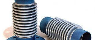
Hose
When transporting aggressive chemical media in the system, valves must have high corrosion protection - the best option in this case is to use hose-type devices. The unit has a working channel in the form of an elastic flexible hose, which, when the flow is blocked, is compressed in the middle part.
Rice. 11 Hose type valve - operating principle