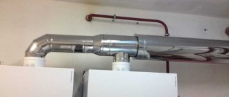
A mixing unit, or manifold, in a warm water floor system is needed to adjust the temperature of the coolant. The latter is heated by the boiler according to the parameters specified by the device program. Typically the supply temperature of the heating medium is 55 °C. This is enough for the heated floor to warm up to a temperature of 30 °C. This is the most comfortable value for the cold season.
If there is a collector, the high supply temperature does not matter - the mixer itself will lower it to the desired value by mixing in cold water. Accordingly, if a water floor without a collector is planned, then the coolant must arrive at a predetermined temperature, from which we can conclude that a separate boiler must be installed for a warm floor without a mixing unit.
Thus, for individual radiator heating you need a second boiler or a centralized communal radiator system. According to state standards, the temperature of coolant supply to radiators is on average 70-80 °C, which is 20 °C higher than required for heated floors.
Regulations and restrictions
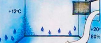
The main feature of water-heated floors is that they are not high-temperature. According to regulations, heating of the coolant in this system should not exceed 55 degrees. But in practice, the standard is considered to be from 35 to 45 degrees.
It is worth noting that the temperature of the liquid circulating through the pipes differs from the degree of heating of the floor. If there are 35 - 45 degrees near the water, the surface will warm up to an average of +28.
According to the standards, the recommended floor temperature for private houses or apartments is:
- kitchen, bedroom, living room - 26 degrees;
- in rooms where people are not constantly present (bathtub, toilet, corridor) - 31.
A warm water floor is an independent pipeline, which can be single-circuit, double-circuit, or even multi-loop, so the design requires a separate circulation pump.
It can be built into the boiler, or can be located separately. With its help, not only the movement of water is carried out, but also the temperature difference of the liquid at the inlet and outlet is adjusted. According to the standards, the permissible difference is 10 degrees.
Important! When choosing a pumping device, the main thing is not to make a mistake with the power. The maximum permitted coolant speed is 0.6 m/s.
Based on these standards and restrictions, you can assemble a heated floor with your own hands.
Making a collector with your own hands
If you decide to assemble a homemade manifold for underfloor heating, you should have some experience and understanding of the design of heating systems. First of all, it is necessary to familiarize yourself with the principle of operation and the task of the collectors, and then carry out competent calculations and actual manufacturing.
Calculation
The heating floor collector circuit is selected based on the characteristics of a particular system. First of all, it is necessary to carry out calculations and select pipeline sections. Before production you must:
- Using a pre-developed scheme, determine which branches the underfloor heating system will consist of and their characteristics.
- Calculate all the operating parameters of the system: the temperature of the hot water supplied to the collector, the coolant flow through all branches of the heated floor, the location of the sections.
- It is important to find out the presence and number of heating devices other than those that will be connected to the distribution manifold.
- Select the regulation and control system to be used in the distribution manifold.
- It is necessary to decide on the location of the collector, since its design and the location of the outlet pipes depend on this. Completing this step allows you to connect the heated floor collector optimally.
To create a good distribution manifold that will allow you to properly control heated floors in the house, it is important to pay special attention to the selection of all components and parts. They must be designed to work in such systems.
In order for the selected manifold to perform its function efficiently and not create additional hydraulic resistance for flow movement and noise, the selection should be guided by the following rule: the diameter of the distribution manifold must be selected in such a way that its cross-sectional area is equal to or greater than the cross-sectional area of all pipelines that connected to the device. The same applies to the collecting manifold.
That is, for example, if 4 pipelines with an internal diameter of d=20 mm are connected to the collector, then the cross-sectional area of the collector should be: S = 4(πd²/4) = 1256 mm². That is, the diameter of the pipe for the collector will be at least 40 mm. This rule for the equipment of heating networks is described in particular in the following regulatory document: STO RAO UES of Russia “Heating points of heating networks”.
Accessories
When choosing a set of elements included in the manifold, you need to focus on the following products:
- A comb, which is a piece of pipe with taps cut into it for connecting a heated floor pipeline. They can be purchased separately, welded from metal or soldered from polypropylene elements. For a manifold that is on the supply side, it is necessary to have a control valve on each circuit.
- An air vent, which is connected at the top of the product to relieve air collected in the system.
- Brackets that allow high-quality installation of a heated floor collector on a building structure. You can choose them from standard ones or make them yourself.
- Drain valve, thanks to which it is possible to remove coolant from the system.
- Tees and connecting elements.
- Fastenings for connecting metal-plastic or polyethylene underfloor heating pipelines.
Components for the collector.
This standard set of elements is suitable for manifolds made of different materials.
The direct collector unit for a heated floor, in addition to the collector itself, includes a large number of additional elements that allow you to regulate and control the system. It includes a three-way or two-way valve, a pump, shut-off and control valves. The connection diagram of the collector in each option depends on the type of equipment selected.
How to connect to central heating
It is possible to connect water heated floors to a centralized heating system in a private house, but requires a special permit.
How to connect a heated floor to a heating system
For the installation of hydrofloors in an apartment, such permission is very rarely issued, since there is a risk of lowering the temperature in the neighbors’ batteries.
The equipment will operate efficiently if two conditions are met:
- the water in the pipeline should not have a temperature higher than 55 degrees; overheating can damage the floor covering;
- The coolant flow in the loops must be calculated in such a way that this does not cause a decrease in the temperature in the radiators, otherwise the installation of heated floors will not lead to a change in the level of heating of the room.
Installing a heated floor without using a mixing unit
The need to install a pump is completely eliminated if you purchase and install a boiler with a built-in pump. The main advantage of such a boiler is its well-chosen equipment. This means that you should not choose a boiler based on any characteristics; it is enough to determine the required power.
The installation methods described do exist, but it is better to purchase all the elements once, connect the heated water floor system correctly and not worry that the money spent on installing such a floor will be wasted.
Average score of ratings is more than 0
Share link
Comments There are no comments yet, but you could be the first...
Radiator connection
Powering a heated floor from a radiator operating both from central heating and from an autonomous boiler (how to choose, power calculation, boiler connection diagrams) is the easiest way. The connection can be made by directly connecting the ends of the circuit to the battery supply and return pipes; we suggest that you familiarize yourself with the various connection diagrams.
How to connect a section of a heated floor to a radiator branch.
Proper operation of the device, with this method of connecting a heated floor, can be achieved:
- if the common boiler has the automatic ability to maintain the temperature in the system;
- if the size of the heated room is maximum 10 m2;
- with a powerful pump to ensure fluid circulation;
- if each radiator is equipped with a separate collector.
This connection of a heated floor in a private house is not considered the best option, since:
- The movement of water is carried out along an easier path, that is, along the main line and batteries. But through the loops of the heated floor, the rate of fluid circulation will be much lower, this will lead to a decrease in temperature.
- If you increase the temperature in the system, the floor surface will overheat.
An alternative solution in this situation is to install a thermostatic valve.
How to choose
How to choose the right mixing valve, Warm floors from A to Z, part 3
Warm hydrofloor is a modern heating system, the efficiency of its operation is ensured by various devices, these include a thermostatic valve.
When choosing a mixing unit, its flow capacity should be taken into account. It is necessary that it can process the water produced by the heating system. These data are indicated in the documentation for the boiler.
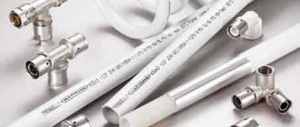
For sexual pipelines, pipes measuring 26 mm are most often taken. The diameter of the thermostatic valve pipes must correspond to their size. Otherwise, you will need to install an adapter, which is not recommended, since the seams will be under constant pressure, and their tightness will need to be monitored.
In addition, the equipment should be selected depending on the temperature of the coolant in the floor line, from 55 to 35 degrees.
If you choose from manual or automatic equipment, then the presence of automation will facilitate the process of operating underfloor heating, create an acceptable microclimate in the house, and save resources, but it is more expensive. The use of a programmable device will allow you to adjust temperature indicators depending on the time of day and day of the week.
When installing warm water floors in a small room, you should not buy expensive equipment; a simple two-way valve will do.
When purchasing a device in a store, check for a certificate, warranty, and manufacturer’s instructions for installation and operation.
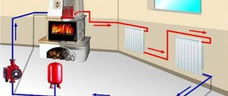
How to connect to the boiler
An economical option, if you have any own boiler (gas, steam, running on liquid or solid fuel) in a private house, is to use a circuit for connecting a water heated floor directly to it. This is very convenient, since the floor will work regardless of the heating in the room, even in summer if necessary.
All necessary fittings are connected to the boiler. A circulation pump is connected; there are modules where it is already mounted inside the container. From the tank, water goes to the collector unit, where it is distributed along the contours of the floor. Having passed through the loops, the liquid returns to the thermogenerator through the return pipe.
The advantage of this method is the ability to adjust the boiler to the heating level of the coolant required for heated floors.
The main features that you need to pay attention to when installing such a structure:
- When using a gas device, it is recommended to connect a condensing boiler - this will achieve the highest efficiency of the system and extend the life of the heat exchanger.
- When using a solid fuel boiler, a buffer tank will be required. Without it, it is difficult to adjust the heating level of such devices.
If there is a stove in a private house, it can be used instead of a boiler, and water floors can be connected directly to it.
But for this, a heat exchanger must be installed above the firebox, to which the floor pipes are connected. It will also be necessary to install a pump to circulate the liquid, and a mixing unit to dilute the water to the desired heating level.
2. Warm floor: Connection diagrams to the boiler and heating system. Warm floors from A to Z.
The nuances of installing heated floors without a mixing unit
In some cases, installing a manifold for a heated floor is not justified
The main disadvantage of installing a system without a collector is the need to minimize coolant temperature losses along the path “coolant heater – pipeline” and in the system itself. You also need to maintain the required temperature on the floor area. Therefore, it is recommended to take into account the following requirements:
- Insulation of room walls;
- Laying thermal insulation on the floor;
- Availability of high-quality window systems;
- Laying the floor in close proximity to the heating element;
- The area of the room is no more than 20-25 m2.
The main and common mistake when installing such a system without a collector unit is trying to install it on too large an area.
Important! It is necessary to calculate the length of the circuit and its layout so that the return temperature of the coolant is not too low. Otherwise, a large amount of condensate will form on the boiler heat exchanger, which will lead to rapid breakdown of the device.
However, some craftsmen argue that in a situation where the “return” will be cold in any case, installing a condensing boiler can save the day. It has high efficiency and such a device is not afraid of low temperatures for heating.
Three-way valve circuit
Connecting a heated floor to the heating system in a private house is often done using a three-way valve. To build such a structure you need to have:
- heating radiators, with a coolant heating level of up to 70 - 80 degrees;
- heated floor contours with water heated to 40 C.
The main task is how to cool the water coming from the radiator to the desired degree. This problem can be solved by using a three-way thermostatic piston. It is installed on the supply pipe, and after it a circulation pump is mounted. In the process, hot water is mixed with cooled water, which comes from the return pipe of the heated floor, until the desired temperature level is obtained.
However, such a combined heating design has one drawback - the inability to regulate the flow of waste coolant. This will lead to periodic supply of either excessively hot or cold water to the circuit. This deficiency affects the performance of the floor.
Differences can be partially compensated using a concrete screed. But it is difficult to calculate the optimal thickness of the concrete layer.
It is impossible not to mention the advantages of this method:
- ease of installation;
- reasonable cost of equipment.
This option is justified for a small private house. In addition, the use of a three-way valve allows you to assemble this structure yourself.
In this section I will tell you how to make a heated floor with your own hands. Let's consider the installation of heated floors. Taking into account my many years of practice, I will tell you how to save on materials and how to correctly make a heated floor design. You do not have to buy expensive equipment in the form of mini circuits for mixing units. Knowing the schemes and devices for the operation of a heated floor, you will be able to design any scheme on the fly and solve the problem of a heated floor.
This article is a complete tutorial on designing underfloor heating. Knowing the physics of phenomena, you will understand the principle of arranging heated floors. This information will help you avoid costly problems with your underfloor heating installation.
And it's free!!! This article was developed by a specialist with many years of work experience and experience in installing heated floors.
This article will also serve as a permanent reference for those involved in water supply and heating systems.
This article will provide illustrative examples and connecting nodes for underfloor heating. We also solve typical problems.
I’ll tell you in simple, understandable language for dummies how to install a heated floor!
In this section you will learn:
Explanation for each element of the heated floor cake:
1. The polystyrene foam board serves to prevent heat loss down into the concrete slab or into the lower room. The polystyrene foam board must have parameters of at least 35 kg/m3 to prevent destruction when loaded from above. Typically, for the first floor, which has an unheated lower room (basement, etc.), a polystyrene foam board with a thickness of at least 100 mm is installed. For subsequent floors 50mm. Sometimes laying up to 50mm thick is allowed. For acceptable floor heating, the thickness of the polystyrene foam board should not be less than 30mm. The polystyrene foam board lies on a flat floor surface without gaps; if there are unevenness in the floor, then such differences are covered with screenings and leveled over the entire floor, and then the polystyrene foam plate is placed on the screenings.
2. The second layer on the polystyrene foam board is either foil penofol or plastic film. Since foil penofol is foamed polyethylene covered with foil, it has, like polyethylene film, a waterproofing effect. This effect prevents vapor permeability between the concrete floor and the polystyrene foam board. If moisture does not pass from one environment to another, then the climate improves in terms of thermal insulation properties. This waterproofing effect reduces heat loss to the bottom, thereby saving thermal energy. And the foil layer additionally increases the insulation in terms of vapor permeability, as it is known that various metals have great resistance to the permeability of various substances. Also, the important effect of foil is its ability to reflect heat rays, which also adds the effect of reducing downward heat loss. Also, polyethylene film and foil reduce the penetration of harmful substances from the polystyrene foam board, since it is known that polystyrene foam is a harmful substance. Whatever you say, you will have to breathe polystyrene foam fumes in small quantities. Another nuance will be that the exposed foil in foam foil when poured into a concrete screed can quickly be destroyed by the chemical reactions of the solution. Roughly speaking, the solution eats up the foil if it is very thin. Find out from sellers about foiled foam foam, special for heated floors using the wet method (that is, concrete heated floors). Foil penofol for heated floors can be protected from corrosion of the foil or it can be sufficient with a thick layer of foil.
3. A steel mesh with a certain pitch serves to strengthen the base of the concrete screed of the heated floor. The mesh located in the lower layer, when the concrete screed is deformed, goes into tension, and thereby increases the strength of the concrete screed against fracture. In addition, the mesh makes it possible to attach a pipe to it. The pipe is attached to the mesh using plastic clamps, which are sold in electrical stores. The mesh itself is attached with dowels and nails of a certain length through the polystyrene foam board to the floor slab. The mesh is connected to the dowel-nails through a metal mounting tape.
4. The damper tape serves to prevent destruction of the concrete screed from thermal expansion of the concrete screed itself.
Filled with a high-quality concrete screed (Cement + screenings. Do not place large stones.). To prevent the screed from cracking, you need to water it in the morning and evening with cold water for the first week, or better yet, buy a “plasticizer” special for this purpose, which is diluted with the concrete mortar and prevents cracking. At worst, consult with specialists on how to make a smooth screed so that it does not crack. Special additives or additives are sold. The thickness of the screed is no more than 5-7cm. the distance from the pipe is 1-3 cm, provided that there are still ceramic tiles on top. If there are no tiles, then leave 3-4cm from the pipe. When the concrete screed dries, do not run hot water through the pipes. It’s better to just leave it under pressure of 1.5-4 atmospheres. What they write needs to be kept up to 6 atmospheres and so on is also an overblown myth. Everything works and does not deteriorate. And you leave the pressure in order to detect pipe defects and detect leaks during pipe damage. And that's all...
Don't worry about the screed! Any screed will do. And don’t listen to all sorts of companies that promote their technologies. Supposedly their floor transfers heat and so on well. This is again an overblown myth. The difference is again very small. Because of some small percentages, such PR is inflated “Mom, don’t worry!”... The main thing is that the smaller the thickness of the concrete floor screed, the better the heat is transferred. Since concrete itself plays a small role in thermal insulation. That is, it resists heat transfer. Do not place parquet on a heated floor. Parquet is also a kind of heat insulator, but it is stronger than concrete and ceramic tiles. Definitely lay ceramic tiles on a warm floor. It is allowed to lay parquet only in warm regions. Here, with 30 degree frosts, this is not possible. Of course, you can put parquet or wood. But you lose a lot of heat coming from the floor. Therefore, you should add heating power to other heating devices (radiators).
How long should the pipeline be in the heated floor circuit?
It all depends on the specific case. Below I will show you a table showing the resistance to water movement in pipes. And you must understand what length to choose!
For those who are afraid to count - practical experience:
For 16 metal-plastic pipes up to 80 meters.
For 20 pipes up to 100 meters.
If you look from the point of view of economy, then the shorter the pipe, the more economical the floor heating system is, and it doesn’t matter that there are many circuits.
If it’s reasonable, then for 16 pipes this is 65 meters.
For 20 pipes 75 meters.
Since the pump consumes energy, it is advisable to waste less energy. From hydraulics it follows that the slower the water runs in the pipe, the easier it flows. The longer the pipe, the stronger the flow resistance. So there is a limit that the pump cannot provide such a pressure that exceeds the resistance to movement. As a result, the flow rate in the pipe is so small that it becomes insufficient to heat the heated floor.
For good floor heating of 10 m2, a flow rate of at least 2 liters/minute is required.
Accordingly, 20m2 requires at least 4 liters/minute. For 20m2, 2 or more circuits are required. If there are two circuits, then for each circuit 2 liters/minute and then 4 liters per minute for the floor of two circuits.
If you lay a pipe that is too long, you will end up with a not entirely economical system. Firstly, the resistance to movement will be greater and for a reasonable flow rate you will have to use more powerful pumps and, accordingly, lose additional energy. If the flow rate is not sufficient, you will not receive the necessary heat for the heated floor. It will simply heat weakly. Since little warm liquid will flow through the pipe.
Below there will be a specific algorithm for calculating the length of the pipeline, but after you get acquainted with the diagrams that are designed for heated floors.
The following is a graph for a metal-plastic pipe (also suitable for a cross-linked polyethylene pipe):
This graph is taken from reliable sources, developed by a world leader in plumbing and heating systems. The data indicated is a pipe length of one meter. I checked it myself with my own formulas. I will say that 1 meter of pressure = 10,000 Pa. And for your task: You multiply the result of the pressure loss by the number of meters and get the total pressure loss per pipe.
Personal calculations:
Table 1
Types of mixing units for warm water floors?
The mixing unit plays a very important role in a water heated floor system. Mixes the main flow with the flow for underfloor heating circuits. To get additional consumption for underfloor heating circuits.
Do you want to know how to make a heated floor without a mixing unit?
Such a warm water floor can be made only through a three-way valve, and without a pump! You can find out how to make a heated floor without an additional pump using a three-way valve here: Three-way valve and heated floor diagrams.
The unit diagram for a heated floor can have several options. Let's consider the simplest visual option, where there are no special problems.
Heated floor connection diagram.
Let's now look at the heated floor mixing unit in more detail:
See the diagram.
The bypass valve is used to allow or not to allow heat from the boiler into the floor heating system. Usually a thermostatic valve with a thermal head is installed there. The thermal head must have an application sensor. This sensor is applied to the supply pipeline in the heated floor circuits.
For this type, the bypass must follow the main diameter of the coolant passage.
The disadvantage of this system is that when the circuits stop, the pump will have nothing to pump. But this problem is solved by adding a second bypass between the supply and return manifolds.
Scheme 1:
Sequential mixing type.
By the way, in place of the bypass valve, you can install a balancing valve or a regular ball valve, but this type requires constant monitoring. Therefore it is not recommended.
The only and currently useless advantage of this scheme is that the outgoing flow from the mixing unit towards the boiler is lower and equal to the floor temperature. From the point of view of thermal engineering, this approach is more correct and more productive.
Scheme 2.
Parallel mixing type.
In any circuit, a bypass valve can be installed in place of the bypass. It serves to begin to pass a flow through itself at a certain pressure. This makes it possible not to constantly drive water through the bypass when the circuits are activated. When the circuits are all closed, the bypass valve begins to allow liquid to pass through itself so that the pump does not work under load, thereby saving energy. In fact, in what cases should the contours be closed? The fact is that in advanced houses there is climate control, which, as it heats up, can block the circuits. And when a situation arises in which all circuits close, then a bypass with a bypass valve comes to the rescue. It helps the pump produce flow. If the pump does not pump to the load, it consumes less energy. The bypass valve has a mechanical adjustment of the required pressure at which it begins to pass liquid. In general, there are also electrical operations in which the pump simply turns off. But about this complex phenomenon some other time.
The disadvantage of this system is that the outgoing flow from the mixing unit is equal to the temperature of the coolant entering the heated floor. The temperature that enters the heated floor circuit is equal to the temperature leaving the mixing unit towards the boiler.
Scheme 3.
Parallel mixing type.
Scheme 3 resembles Scheme 2 in many ways, and practically in terms of functionality it is not much different. The only difference may be in the ease of assembly.
The throughput (thermostatic) valve does not necessarily have to be of good permeability or a large diameter, as practice shows that the permeability can vary greatly and this does not spoil the mixing unit. Since the pump can greatly influence the flow through the bypass (thermostatic) valve. With its tightening force, it greatly increases the water flow through the bypass (thermostatic) valve. In addition, the flow rate through the valve is approximately two times lower than the flow rate of the pump.
In order to maintain good permeability in this scheme, it is necessary to have good permeability through the circulation pump. That is, the ring itself from the return manifold through the pump to the supply manifold had a good ideal passage without narrowing. Three-way valves with a temperature-sensitive element cannot be installed in this circuit. Since three-way valves have a small permeability, this results in high local resistance.
Read more about the three-way valve.
The three-way valve should be installed like this (See Diagram 4):
Scheme 4.
Sequential mixing type.
The three-way valve itself is designed to pass water from one branch to the other two branches, depending on the rotation of the valve. That is, in this circuit it is not necessary to install a valve that opens or closes one line. And smoothly opening one line and closing another. The line where the pump is located is always open. When the valve sensor cools, the incoming heat line from the boiler opens and the bypass line closes. When heated, the reverse procedure occurs. Only the valve described above is mounted in this circuit 4.
I have already said that these three-way valves with a thermostat themselves have poor flow, and I do not recommend using them at all. Only for low productivity. Within 3 - 4 heated floor circuits. But there are schemes that allow you to install any three-way valve. More details about the schemes below.
Well, if you already have a three-way valve with a remote sensor, then for good pumping you can install it as indicated in diagram 5. But this is not an ideal diagram. There are other schemes.
Scheme 5.
Parallel mixing type.
If it is a three-way system without a remote sensor, then according to scheme 4. Since with scheme 5, cooled water from the circuits does not enter the sensor input. And it will close immediately when hot water arrives.
Now let's talk about the schemes in more detail.
We considered the above described schemes as a kind of option for your imagination. So that you can understand what assembly options exist for mixing units.
Below is a much better diagram...
To date, I have discovered one important feature: a wide variety of schemes are divided into two types of water (coolant) mixing.
This is: Parallel
mixing type and
sequential
mixing type of mixing unit.
To understand this, let's look at a visual diagram.
Arrows indicate water flows. The floor is a contour of warm floors.
Which scheme do you think is more productive? Consistent of course! In a sequential circuit, the entire pump flow goes to the underfloor heating circuit. And in a parallel circuit, the pump flow rate is divided with the inflow flow rate of the inlet circulation. Therefore, if you want to squeeze the maximum efficiency out of the pump for underfloor heating circuits, then you definitely need a sequential mixing unit system. And it is not discussed.
Also, with a sequential circuit, it is possible to install many more circuits in one mixing unit. Since the cost of flooring can be much higher. While on the parallel type, the pump flow is shared with another circulation ring.
So that you understand which circuits belong to sequential and parallel types, let's look at the circuits.
Parallel circuits of mixing units:
Sequential schemes of mixing units:
The sequential system is better in that all the pump flow goes into the heated floor circuits. This stream is not divided. This makes it possible to create a large number of circuits in one mixing unit.
Do you want to know how to make a heated floor without a mixing unit?
Such a warm water floor can be made only through a three-way valve, and without a pump! You can find out how to make a heated floor without an additional pump using a three-way valve here: Three-way valve and heated floor diagrams.
Do not forget! The diagram does not indicate automatic air vents. I hope it won't be difficult to figure out where to put them. Place it at a high point on the supply and return manifold. Keep in mind and think that the pump rotor does not spin in the air.
We have not considered the option when there is one circuit for a warm floor. In principle, such a mixing unit is quite possible for one circuit. Only the diameter of the pipes can be reduced, and the power and flow rate of the pump can be reduced by three times. More details below.
You can find out which diagrams to apply to three-way valves here.
Which pump should I use for a warm water floor?
Standard circulation pumps for heating are sold on the market with a flow rate of 2.5 m3/hour, which is about 40 liters/minute and a pressure of up to 6 meters. The higher the pump pressure, the faster the flow rate in the heated floor circuit. For heated floors, there is a standard pump standard with parameters (2.5 m3/h with a head of 6 m).
If the pump indicates that its flow rate is 40 liters per minute, then in reality this does not mean that it will pump like that. It all depends on the throughput of the system itself or the underfloor heating unit. Let’s say if you have many long circuits, then they provide sufficient resistance to movement, as a result of which the pump flow rate decreases.
Approximate schedule of all pumps:
And now the real graph of such a pump (2.5 m3/h with a head of 6 m):
Schedule 1.
Now remember, the better the transmittance, the less pressure appears on the contours. The more branches (circuits) in one mixing unit, the higher the flow rate and, of course, the lower the pressure on all circuits. So you need to not go too far! If a pressure of 3 meters is required for good pumping of the circuit, then it is necessary to maintain the flow rate according to the schedule and not increase the number of circuits.
How to find out the entire flow rate in the mixing unit for a parallel circuit?
1. Calculate the recommended consumption in each branch. Add up all the expenses of the branches.
2. Calculate how many losses all branches (circuits) will produce. But in fact, the amount of losses can be used to determine the constant flow of incoming heat into the mixing unit. It is usually equal to about 40-100% of all circuit flows. That is, if the entire amount of circuit flow is 15 liters/minute, then the incoming heat flow is approximately 6-15 liters/minute. This depends on the temperature difference between the incoming temperature and the temperature set by the thermal head. Also affect the consumption and heat loss of the floor itself. That is, if the temperature from the boiler is 60 degrees, and the mixing unit is set to 40 degrees, then the flow rate will be approximately 40%. And if the temperature from the boiler is 75 degrees, and the mixing unit is set to 40 degrees, then the flow rate will be approximately 25%. You also need to take into account the bypass; if there is one, then there is also a constant flow through it. Add about 6 liters/minute to the bypass. If the pipes are long, then the heat loss is correspondingly greater, and accordingly the thermal head begins to transmit more heat, which means that the pump flow rate increases and, accordingly, the pressure drops.
And if it’s really hard to understand, then consider it this way:
1. Calculate the recommended consumption in each branch. Add up all the expenses of the branches.
2. Multiply all flow rates of the branches by 2. That is, if the flow rate of all circuits is 15, then the total flow rate of the mixing unit pump itself should be 30 liters/minute.
How to find out the entire flow rate in the mixing unit for a sequential circuit?
1. Calculate the recommended consumption in each branch. Add up all the expenses of the branches. Since in a sequential system the pump flow goes entirely to the underfloor heating circuits, it is enough to add up only the flow of all circuits.
Check the resulting flow rate with the graph and find the pressure loss indicated by the graph. There is a flow scale on the horizontal coordinate, from the desired scale you go up, rest on the line and then move horizontally to the left and get a pressure scale. The schedule for other pumps is original. You can simply manually draw the scale of your pump and draw an arc in it as shown in graph 1. Since all pumps operate according to a standard curve. And depending on the pressure, you can select the required pipeline length from Table 1.
Consider one more feature!
! This is that if a pump with a pressure of 6 meters, in fact, as usual, produces less pressure, for example 5 meters. If the flow rate is 40 liters/minute, then it can produce 30 liters/minute. This happens due to various factors: Loss of voltage in the network. Local resistance of the tee nodes themselves. Some narrowings in the pipes, turns, etc. And as a result, you need to consider the pump service life to be approximately 15% lower. Only then will you do the right thing.
Here is a graph of practical experience for a pump with parameters (2.5 m3/h with a head of 6 m):
Schedule 2.
How to find out what length of pipe is needed for a heated floor.
To calculate this, you need to know the water flow in the pipe for a given pipeline length for a certain floor area. Also, per 10m2 there should be a flow rate of at least 2 liters/minute. Depends on heat loss. Below are the details.
Using Table 1, find the pressure loss. And so that the pressure at the entrance to the circuit is not lower than the pressure loss through the pipe at a certain fluid flow rate.
And the pressure in one mixing unit is the same for all circuits. The pump creates one pressure for all circuits. We calculate the pressure according to graph 2.
Don't get confused!
This is a complete solution. Read below about the installation step and then it should be clear about the length of the pipeline. The main thing is not to make the pipe too long.
To put it simply, for every 10 meters 16 pipes you need to pump at least 0.4 liters/minute. That is, for 50 meters of pipe you need 2 liters/minute. And for 80 meters of pipe 3.2 liters/minute.
The complete solution is:
| The pump pressure (see graph 2) should not be lower than the pressure loss along the length of the pipeline at a certain flow rate of one circuit. Find the pressure loss in the pipeline of one circuit using table 1. The pump pressure is according to schedule2 at a certain flow rate of the entire mixing unit. |
Table 1
Keep in mind that if you install a mixing unit on your already clogged heating system, then perhaps with this mixing unit you will take away some flow from the boiler, which may affect the flow in other heating branches. This problem is solved by adding a hydraulic separator, with additional pumps.
As for the losses on pipe bends, they are very small; for example, to obtain a resistance of 1 meter at a speed of 0.44 meters/second, 200 turns (90 degrees) are required. As a rule, there can be a maximum of 40 of them on one circuit.
It is very important to know that if you use antifreeze liquid in the heating system, then the antifreeze liquid differs in viscosity from water by 30% to 50%. This means that water will flow through the pipes even slower. And the calculations need to be done differently. It is necessary to add a reserve of pump power by approximately 20% or shorten the pipes by 20%. Also keep in mind that the heat capacity of the antifreeze liquid is again about 20% less. This means this liquid will transfer less heat.
How many underfloor heating circuits can be assembled in one mixing unit?
Based on golden experience:
From experience, I can say a pump with a flow rate of up to 40 liters/minute and a head of 6 meters for a parallel system, up to 8 circuits of a long pipe not exceeding 65 meters for a 16 pipe is enough.
For a sequential system, up to 12 circuits of a long pipe not exceeding 65 meters for 16 pipes are sufficient.
If you decide to make pipes 80 meters long, then you should make 5 circuits for a parallel system, 8 circuits for a series system, for one such pump.
Just don’t try to make the circuit 100 meters long with 16 pipes, it’s not very economical! Tested from my own personal experience!
And in general, I don’t recommend even making a 20 pipe 100 meters! It’s better to make two circuits of 50 meters each from 16 pipes.
I recommend that the pipe length not exceed 80 meters. Even for 20 pipes. Use only 16 pipes. They bend well. And the laying step becomes available for strong bending.
And if you decide to count more specifically.
An algorithm for solving this problem for a parallel system.
Let's say you have 6 heated floor circuits. You have also decided on the length and it is about 80 meters. You have also decided on the flow rate and it is 3 liters/minute for each branch.
Now we count:
See table 1
.
80 meters of pipe with a flow rate of 3 liters/minute gives a pressure loss of 2.16 meters.
We calculate the entire flow rate: The number of circuits with a flow rate of 3 liters/minute gives a total flow rate of 18 liters/minute. We multiply this flow rate by 1.5 times and get 27 liters per minute. We check schedule 2 (see above). The graph shows that the pressure is about 1.3 meters. See table 1
and we see that the flow rate on a branch of 80 meters will be within 2 liters/minute.
To achieve a flow rate of 3 liters/minute in each branch, you need to either increase the power of the circulation pump, which is not economical. Or divide 6 branches in half and place one mixing unit for every 3 branches. Which is also not economical. The next option remains. Shorten the pipes in the circuits and increase the number of branches. This option is more economical. From the point of view of the costs of pumping water through the branches.
We need 18 liters/minute! We can divide 18 into 8 branches and get a flow rate of 2.25 liters/minute for each branch. The length of the branch will already be about 65 meters. But the lengths of each branch may be different. Then you need to calculate where what flow is needed. But more on that later. Since you don’t yet know how to determine the laying step.
An algorithm for solving this problem for a sequential system.
Let's say you have 6 heated floor circuits. You have also decided on the length and it is about 80 meters. You have also decided on the flow rate and it is 3 liters/minute for each branch.
Now we count:
See table 1
.
80 meters of pipe with a flow rate of 3 liters/minute gives a pressure loss of 2.16 meters.
We calculate the entire flow rate: The number of circuits with a flow rate of 3 liters/minute gives a total flow rate of 18 liters/minute. We check schedule 2 (see above). The graph shows that the pressure is about 2.5 meters. See table 1
and we see that the flow rate on a branch of 80 meters will be within 3 liters/minute. Result: Fits!
How to determine the installation step of a heated floor?
To determine the installation step, you need to know the heat loss of the room itself. And what quality of heat do you want to receive? But we will not calculate the heat loss of the house, since this need not be done. Gold experience is enough.
From golden experience, for the harsh climate of Russia within -30 degrees for a normally insulated house:
If you want to receive underfloor heating without other heating sources, then the laying step should be at least 10-12 cm. If in combination with batteries (radiators), then 15-20 cm. I don’t recommend doing the installation step anymore, as there is a noticeable difference in heating across the floor area.
As for the length of the pipe, it depends on the required water flow through the pipe and sufficient pressure to pump it.
Regarding consumption:
With a laying step of 10-12cm per 10m2, it is necessary to pump 2-3 liters/minute.
With a laying step of 15-20cm per 10m2, it is necessary to pump 1-2 liters/minute.
To be more precise, for every 10 meters 16 pipes you need to pump 0.4 liters/minute. That is, for 50 meters of pipe you need 2 liters/minute. And for 80 meters of pipe 3.2 liters/minute. The longer the pipe, the greater the heat loss in the circuit.
That is, the shorter the pipe, the less water can be pumped through the pipes. Proportional to heat loss. But the higher the flow rate in the pipes, the greater the efficiency of the floor.
By the way, if you have more than 3 circuits in your mixing unit, then you definitely need to take manifolds with flow meters. The manifold data shows the flow rate in each circuit. And if the contours are very different in length, including the laying step, then it will be possible to adjust each contour according to the amount of flow. Since there is a rotating element that drives the valve for the necessary passage of water.
The following proven mixing units are sold on the market:
combimix
Download CombiMix 1.0 program
dualmix
Video tutorial on calculating a mixing unit
Go to Video Course
If you are a fan of specifically calculating the physics and mathematics of phenomena, then it will be interesting for you to get acquainted with personally developed articles on Hydraulics and Heat Engineering.
If something is unclear, write in the comments, since I am both the administrator and moderator of this site, and I am also the author of this article. I receive notifications about added comments, and I read them.
Just click on the text “comments” and then click on the text “Add comment”.
| Like |
| Share |
| Comments (+) [ Read / Add ] |
All about the country house Water supply Training course. Automatic water supply with your own hands. For Dummies. Malfunctions of the well automatic water supply system. Water wells Well repair? Find out if you need it! Where to drill a well - outside or inside? In what cases does cleaning a well make no sense Why pumps get stuck in wells and how to prevent it Laying a pipeline from a well to a house 100% Protecting the pump from dry running Heating Training course. Do-it-yourself water heated floor. For Dummies. Warm water floor under laminate Educational Video course: According to HYDRAULIC AND THERMAL CALCULATIONS Water heating Types of heating Heating systems Heating equipment, heating batteries Heated floor system Personal article on heated floors Operating principle and operating diagram of a heated water floor Design and installation of a heated floor Do-it-yourself water heated floor Basics materials for heated water floors Installation technology of water heated floors System of heated floors Laying step and methods of laying heated floors Types of water heated floors All about coolants Antifreeze or water? Types of coolants (antifreeze for heating) Antifreeze for heating How to properly dilute antifreeze for the heating system? Detection and consequences of coolant leaks How to choose the right heating boiler Heat pump Features of a heat pump Heat pump operating principle About heating radiators Methods of connecting radiators. Properties and parameters. How to calculate the number of radiator sections? Calculation of thermal power and number of radiators Types of radiators and their features Autonomous water supply Scheme of autonomous water supply Construction of a well Cleaning a well with your own hands Experience of a plumber Connecting a washing machine Useful materials Water pressure reducer Hydraulic accumulator. Operating principle, purpose and configuration. Automatic air release valve Balancing valve Bypass valve Three-way valve Three-way valve with ESBE servo drive Thermostat for radiator Manifold servo drive. Selection and connection rules. Types of water filters. How to choose a water filter for water. Reverse osmosis Sludge filter Non-return valve Safety valve Mixing unit. Principle of operation. Purpose and calculations. Calculation of the CombiMix Gidrostrelka mixing unit. Operating principle, purpose and calculations. Indirect heating storage boiler. Principle of operation. Calculation of a plate heat exchanger Recommendations for the selection of PHE when designing heat supply facilities About contamination of heat exchangers Indirect water heating water heater Magnetic filter - protection against scale Infrared heaters Radiators. Properties and types of heating devices. Types of pipes and their properties Indispensable tools for a plumber Interesting stories A scary tale about a black installer Water purification technologies How to choose a filter for water purification Let's think about sewerage Sewage treatment plants in a rural house Tips for a plumber How to evaluate the quality of your heating and plumbing system? Professional recommendations How to choose a pump for a well How to properly equip a well Water supply for the garden How to choose a water heater An example of installing equipment for a well Recommendations for the configuration and installation of submersible pumps What type of water supply accumulator should you choose? Water cycle in an apartment - vent pipe Removing air from a heating system Hydraulics and heating engineering Introduction What is hydraulic calculation? Discrepancy in hydraulic calculation Physical properties of liquids Hydrostatic pressure Let's talk about resistance to the passage of liquid in pipes Modes of fluid movement (laminar and turbulent) Hydraulic calculation for pressure loss or how to calculate pressure loss in a pipe Local hydraulic resistance Professional calculation of pipe diameter using formulas for water supply How to choose a pump according technical parameters Professional calculation of water heating systems. Calculation of heat loss of the water circuit. Hydraulic losses in a corrugated pipe Heat engineering. Author's speech. Introduction Heat transfer processes Thermal conductivity of materials and heat loss through the wall How do we lose heat with ordinary air? Laws of thermal radiation. Radiant warmth. Laws of thermal radiation. Page 2. Heat loss through a window Factors of heat loss at home Start your own business in the field of water supply and heating systems Question on hydraulic calculations Designer of water heating Pipe diameter, flow speed and coolant flow. We calculate the diameter of the heating pipe. Calculation of heat losses through the radiator. Power of the heating radiator. Calculation of the power of radiators. Standards EN 442 and DIN 4704 Calculation of heat loss through building envelopes Find heat loss through the attic and find out the temperature in the attic Selecting a circulation pump for heating Transfer of thermal energy through pipes Calculation of hydraulic resistance in a heating system Distribution of flow and heat through pipes. Absolute schemes. Calculation of a complex associated heating system Heating calculation. Popular myth Calculation of heating of one branch along the length and KMS Calculation of heating. Selection of pump and diameters Heating calculation. Two-pipe dead-end Heating calculation. Single-pipe sequential heating calculation. Two-pipe associated Calculation of natural circulation. Gravity pressure Calculation of water hammer How much heat is generated by pipes? We are assembling a boiler room from A to Z... Heating system calculation Online calculator Calculation program Heat loss of the room Hydraulic calculation of pipelines History and capabilities of the program - introduction How to make a calculation of one branch in the program Calculation of the KMS angle of the outlet Calculation of the KMS of heating and water supply systems Pipeline branching - calculation How to calculate in the program single-pipe heating system How to calculate a two-pipe heating system in a program How to calculate radiator flow in a heating system in a program Recalculation of radiator power How to calculate a two-pipe associated heating system in a program. Tichelman loop Calculation of a hydraulic separator (hydraulic arrow) in the program Calculation of a combined circuit of heating and water supply systems Calculation of heat loss through enclosing structures Hydraulic losses in a corrugated pipe Hydraulic calculation in three-dimensional space Interface and control in the program Three laws/factors for selecting diameters and pumps Calculation of water supply with self-priming pump Calculation of diameters from the central water supply Calculation of water supply for a private house Calculation of a hydraulic arrow and collector Calculation of a hydraulic arrow with many connections Calculation of two boilers in a heating system Calculation of a single-pipe heating system Calculation of a two-pipe heating system Calculation of a Tichelman loop Calculation of a two-pipe radial distribution Calculation of a two-pipe vertical heating system Calculation of a single-pipe vertical heating system Calculation of a warm water floor and mixing units Recirculation of hot water supply Balancing adjustment of radiators Calculation of heating with natural circulation Radial distribution of a heating system Tichelman loop - two-pipe associated Hydraulic calculation of two boilers with a hydraulic arrow Heating system (not Standard) - Another piping scheme Hydraulic calculation of multi-pipe hydraulic arrows Radiator mixed system heating - passing from dead ends Thermoregulation of heating systems Pipeline branching - calculation Hydraulic calculation for pipeline branching Calculation of a pump for water supply Calculation of warm water floor contours Hydraulic calculation of heating. Single-pipe system Hydraulic heating calculation. Two-pipe dead-end Budget option for a single-pipe heating system for a private house Calculation of the throttle washer What is KMS? Calculation of a gravity heating system Designer of technical problems Extension of a pipe Requirements SNiP GOSTs Requirements for a boiler room Question for a plumber Useful links for a plumber - Plumber - ANSWERS!!! Housing and communal problems Installation work: Projects, diagrams, drawings, photos, descriptions. If you're tired of reading, you can watch a useful video collection on water supply and heating systems
Two way valve
An alternative version of a three-way valve is a two-way valve, it is also called a feeding valve. It ensures that the process of mixing water is not constant, but periodic. That is, the design of the valve contributes to either adding hot coolant or cutting it off from the system.
Mixing unit for underfloor heating on a two-way valve, part 1
The specific scheme is simple and does not allow the floor to overheat. Disadvantage - the heating area is limited, no more than 200 meters.
Connection diagram via pumping and mixing unit
This scheme is also combined - the presence of radiators and heated floors. But to implement this method, it is not a three-way valve that is required, but a more expensive device - a pumping and mixing unit.
The essence of the method is to add cold water to the hot water coming from the boiler. With this method, it is possible to regulate the dose of waste water supply using a balancing valve. This allows you to heat the coolant that enters the warm hydrofloor through the collector to a specified level.
This design is considered effective; it can easily create comfortable conditions in the home. The pumping and mixing unit can be purchased ready-made, or assembled with your own hands in different variations. The configuration of the collector is influenced by your needs and financial capabilities. A node may consist of:
- thermostatic control valve;
- temperature sensor for coolant;
- balancing valve with a fixing clamping screw;
- circulation pump;
- threaded sleeve for an external temperature sensor, with a built-in socket;
- immersion thermometer;
- valves: for restarting the system, rotary-drainage, ball;
- automatic air vent;
- restart bypass;
- taps for connecting the supply and return hoses.
Video - working with a pumping and mixing unit
Water heated floor VALTEC. Diagram of work with the pumping and mixing unit
If you wish, you can install a warm floor according to this scheme yourself in a private house.
Scheme with thermostatic kit for one loop
To build floor heating with a regulator in a house, you will need a small thermal installation kit, which is designed to connect only one circuit. With this method there is no need to arrange a complex mixing unit. This system is designed to heat a room with an area of no more than 20 m2.
Thermal installation kit is a small plastic box consisting of:
- temperature limiter for coolant;
- limiter for adjusting the air temperature in the heated room;
- air vents.
In this design, water enters the underfloor heating circuits directly, and not through the collector group. In this case, the liquid is supplied to the loop heated to 80 degrees, and it cools down inside the circuit.
The process is as follows: high-temperature coolant is supplied in portions, after which the thermal head shuts off the supply. The water cools down in the loops, and the next portion is served.
When using low-temperature coolant, such a kit is not required.
Since there is only one coil, there is no need to equip a special pump to move water through it; the one already in the boiler will handle this task.
Basically, it is recommended to connect such kits as underfloor heating in a private house:
- if you plan to heat small rooms (toilet, bath, balcony), this allows you to save on the purchase of a collector unit;
- in the presence of rooms with a large area of heated floors on the first floor, and the arrangement of such a design in small rooms on the second floor;
- if desired, make another turn, but there are no more outlets on the distribution node.
In any case, installation is simple; the kit is connected to a nearby battery, riser or collector unit. The result is a finished branch.
The downside of the device is the low level of comfort. If the boiler is heated well, the water floor will have an increased degree of heating. Another negative side is that the effective operation of the kit is only possible if there is a two-pipe wiring. It is difficult to connect it to a single-pipe structure; installation of a bypass and a balancing valve will be required.
How to connect to a single-pipe distribution
If there is only one pipe, the system is called one-pipe or “Leningradka”. Previously, this was how everyone in the house was connected to heating. This circuit is trouble-free and reliable. The main disadvantage is a decrease in the degree of heating as the liquid moves.
That is, the battery is hotter at the beginning than at the end. And if a warm water floor is connected to such wiring, the temperature level will drop further and the hydraulic resistance will increase, thereby requiring the installation of an additional circulation pump.
To balance such a device, a number of conditions must be met:
- in order not to reduce the temperature in the radiators, the insertion of a warm hydrofloor should be done after all batteries;
- use DN pipes;
- use this scheme if there are no more than 5 radiators;
- provide the design with a three-way mixing valve to maintain the floor temperature at the required level;
- equip the device with an additional pump for forced water circulation;
- the distance between the inlet and outlet taps must be at least 30 cm.
Installation of a single-pipe heating system with heated floors
Connecting to a single-pipe distribution is not often used when installing water floors, since this method cannot be called stable. In addition, accidents cannot be ruled out, so it is better to connect a warm water circuit to the boiler; it is more expensive, but more reliable.
Scheme with mixing unit
When installing a water floor in a large area, it cannot be connected to an existing radiator heating system. The question arises of how to connect heated floors to heating in a private house - you will need to lay a separate line and install a distribution comb.
Warm Floor! Mixing unit! Connection. Review! The simplest scheme!
Connection according to this scheme is possible in several ways:
- With a circuit length of maximum 50 meters, the comb is equipped with thermal heads that react to the return temperature of each loop separately. Coolant circulation is provided by the main pump.
- Installation of a mixing unit with a manifold, plus the presence of a two-way or three-way valve. When using a spirit valve, it is responsible for mixing hot water and is installed on the supply pipe. Control is carried out using a thermal head with a remote sensor; it is installed in the collector pipe or mounted externally. As the water temperature increases, the sensor puts pressure on the valve stem, thereby closing it. To implement this scheme, it is necessary to install an additional pump.
When installing a three-way valve, the operating principle is the same, but the device is more efficient and is designed for a large volume of coolant.
The disadvantage of this method is the high price of the equipment and complex installation.
Hydraulic separator
The use of a hydraulic separator when installing a combined circuit allows you to separate radiator-type heating from underfloor heating.
If the radiator heating system is equipped with a circulation pump, then installing a second one in the mixing unit will lead to a disruption of the hydraulic mode. So that they can function in parallel, a hydraulic separator or heat exchanger is installed.
Taking into account the features of each scheme, and listening to the advice of the experts, which we tried to outline in this article, you can install a warm water floor in a private house with your own hands.
Features of the operation of mixing units
The node operates like this:
- The hot coolant reaches the floor heating manifold and reaches the safety valve with thermostat.
- When the heating of the working medium exceeds the required level, the valve is activated and the supply of cold water from the return line begins, as a result of which it is mixed with the hot coolant.
- After the temperature reaches the desired value, the valve is activated again and the flow of hot water stops.
The collector unit is responsible for regulating the degree of heating of the coolant and its circulation in the circuit, and consists of two main elements:
- A safety valve that supplies the heating circuit with hot water as much as required, monitoring the inlet.
- A circulation pump that ensures the coolant moves along the circuit at a certain speed, as a result of which the floor covering will be evenly heated over the entire area.
In addition to them, the mixing unit for heated floors and radiators may include:
- bypass, which prevents system overload;
- air vents;
- shut-off and drain type valves.
Depending on the tasks being solved, the mixing unit of the collector can be equipped in different ways. It is always installed before the contour of the heating structure, but the installation location itself is not precisely indicated. For example, the unit can be made in a room where there is a heated floor, or in a boiler room.
When there are several rooms in a building with heated floors, then the mixing units are placed in each of them separately or in a nearby manifold cabinet. The main difference in the operation of these units is the use of different safety valves. These devices come in 2-way and 3-way types.
How to connect a water electric floor?
Warm hydraulic floor is a system in which TENS are installed in a screed or placed under a covering, due to which there is an equal distribution of air flows throughout the room. To install the equipment, you need to make the correct calculations; this will help you lay the pipes correctly. It is also necessary to remember the connection technology so that the heat supply functions without interruption and provides protection from cold in the premises for a long time.
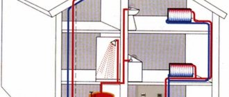
Connection to the boiler
Buildings consisting of several floors are usually not suitable for this option. This connection scheme is better suited for owners of private homes. The characteristic is the temperature of the circulating medium, which can reach 35-38°C in pipes and reaches 80° in heating devices. There are several options for laying TENS:
1. Snake. In this case, the line is a little hotter on the initial turns, which must be taken into account when locating window openings in the far walls.
2. A spiral or snail is suitable for large rooms; the flow in the system is distributed equally.
3. The method of bordering sections involves the installation of pipes with a large pitch in the warm zones of the room and more dense laying in places with possible cold bridges.
4. The combined installation diagram of traditional heating implies a couple of options at the same time, depending on the need to warm up a personal home.
When installing, you can’t do without a pump. Convective circulation occurs exclusively with a small pipe slope and a circuit with a modest area, without connecting heating devices. The collector acts as a water tap and disperses the media through the pipes. Without this component, the liquid temperature reaches 95°, which is unacceptable for a heated hydraulic floor; it will fail quickly.
If the privatized house is less than 100 m2, there is no need to connect batteries; the collector consists of two combs - for supply and return. The cabinet is installed in a comfortable place, shut-off valves and pipes are installed. For monitoring and adjustment, an external water thermostat and sensors are connected nearby. When connecting, use fittings and adapters.
If a warm hydraulic floor is connected to the boiler at the same time as heating devices, the scheme involves installing two collectors, due to the large temperature difference between the devices. The water is heated in the battery to 95°C, while the difference in values from forward to reverse is no more than 25°C, in other words it comes out to 95 to 70. And the ideal value for a traditional heating system should be 30-400C.
Working principle of the collector
The thermostat valve and distributor are located at the connection point to the primary circuit. This element allows you to adjust the temperature to a good value. From the boiler, the carrier enters the system, passes through it and returns back in a cooled state. If the thermostat is set correctly, the necessary balancing of the valve is achieved. Depending on the load, the flow of hot water into the mixer will be sufficient to maintain the temperature.
The warm hydraulic floor is connected to a gas water heater with flow meters on the supply comb. With their help, the largest carrier flow through the circuit is set. The length of the pipe branches is not always the same, so to equalize the resistance in terms of hydraulics and equal distribution of liquid from the boiler to the heating devices, it is worthwhile to provide an adjustment scheme using sensors and thermostatic valves.
Having formed the manifold and positioned it correctly, proceed to connecting the boiler to the floor surface. Usually, for this purpose, an individual room is emphasized where all the equipment and pipes are installed. The return and supply parts are inserted into the unit. The second will supply heated liquid to the heating system, and the first will receive cold water and send it to the boiler for heating. All parts are combined using connectors and installed to the manifold.
Connection to the system
The wiring diagram for autonomous heating can only be used in a private home. In this case, the signal to the thermostat is supplied from a heat sensor placed at a distance. If the indicator can reach the specified value, media feeding automatically ends. A balancing valve is connected to eliminate idle water in the circuit.
The circulation pump provides additional pressure. Connecting a safety external water thermostat is necessary to control the temperature level; it is located on the inlet pipe. The electric drive of the heating system controls the valves of the heating group. The collector distributes the media flows, and the circular pump ensures circulation in a small circle. There can be several remote thermostats. Using these devices, it is convenient to monitor the temperature in any room separately.
Sometimes, instead of a pump, a three-way mixer is installed, which performs a similar function, but under conditions of good circulation. It is fixed at the hot water supply point and connected to the outlet through a circular pump. A Mayevsky tap is installed on the collector to remove oxygen bubbles from the batteries. A drain valve is placed on the return line to remove water from the heating system during repair work.
If necessary, you can use more than ten types of liquid mixing. Such a scheme is very productive, since the output flow towards the boiler will be reduced, and the temperature will be equal to the heat indicator of the floor.
If the circular pump is replaced with a bypass valve and the pressure is adjusted, then the circuit can be closed when favorable heating is achieved. With such a parallel mixing scheme, the pump does not stop working without load, saving electricity.
General recommendations and advice
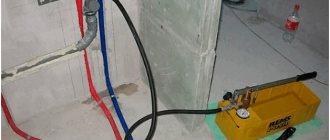
After connecting a heated hydraulic floor to the heating system, the level and tightness of all components should be analyzed. The equipment is turned on, the carrier begins to move under a pressure level of 0.6 MPa. The initial process is carried out for about 40 minutes without reducing the parameters. Then the pressure is increased to 1 MPa for 2 hours, maintaining all the indicators on the thermostat. If the system has withstood the load, we proceed to pouring the screed.
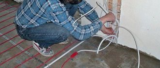
When laying wiring in walls, protection from damage must be provided. To do this, use a corrugated pipe made of polypropylene, which has very high strength. When arranging, the main thing is to keep the loop radius at bends of 5 mm in diameter; when installing, they should not be pulled together tightly.
Since the lengths of the pipes in each circuit are different, after installing the floor, starting the system and its entry into normal operating mode, it is necessary to manually adjust the media flow for a particular branch. The longer the peshel, the higher the amount of water on it. For this purpose, measuring instruments are equipped with specialized floats.
If installation is intended for central heating, the carrier should not be used directly due to the high pressure. In this case, the indicator is 12 times higher than the optimal norm, which is dangerous for the main line to rupture.
The effective distribution of the media between the circuits depends on the connection diagram of the heated hydraulic floors. Simultaneous operation of heating devices is acceptable. Test work is carried out before the screed is poured; first, air is removed from the system, after which the pressure gradually rises. To connect several circuits, it is necessary to install a collector unit.
Mixer purpose
First of all, you need to find out how the mixing unit for heated floors works. It is used only for water underfloor heating, since it has a mechanism similar to radiator coolant. A typical heating circuit is built according to the following plan - a boiler that heats the liquid, circuits of a heated floor and radiators.
The boiler warms up the coolant to a temperature similar to a radiator, usually 95C. Ideally, the temperature should not be more than 31C. There are several reasons for this, especially that for a comfortable feeling the floor should not be very hot or cold.
Things to take into account:
- type and thickness of the finishing coating;
- the height of the heating floor screed in which the tubes are located.
Accordingly, the most suitable liquid temperature in the pipes should vary from 35C to 55C. However, it is very high in the boiler, and it is prohibited to direct such a temperature into the tubes. Therefore, in order to reduce it, a mixing unit is used at the beginning of the heating system. This is where high and low temperatures mix with water. And the already cooled liquid is transferred to the floor tubes. Using the mixer, the underfloor heating system functions throughout the entire house correctly and without interference.
Of course, there are heated floors that work without a mixing unit. But they are equipped with a water heating device that heats the coolant to the optimal temperature.
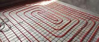
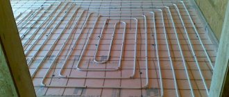
Laying schemes for water heated floors
Methods for laying out floor heating pipes
There are three main ways of laying a water-heated floor: snake, spiral (snail) and a combination of these options. Most often, heated floors are installed with a snail; in some places a snake is used.
Installation diagram "Snail"
Laying a warm snail allows you to distribute heat more evenly throughout the room. With this layout, the pipe is mounted in a circle towards the center, then from a circle in the opposite direction.
When laying out a heated floor with a snail, you need to provide an indent for laying out the pipe in the opposite direction.
Laying heated floors with a snake
With this installation, the underfloor heating pipe is mounted in one direction and, when the circuit is laid out, it simply returns to the collector return. With this device, at the beginning of the circuit the coolant temperature is hotter, at the end it is colder. Therefore, the snake layout is used quite rarely.